CN217906778U - Music book support frame that can tile - Google Patents
Music book support frame that can tile Download PDFInfo
- Publication number
- CN217906778U CN217906778U CN202222029336.3U CN202222029336U CN217906778U CN 217906778 U CN217906778 U CN 217906778U CN 202222029336 U CN202222029336 U CN 202222029336U CN 217906778 U CN217906778 U CN 217906778U
- Authority
- CN
- China
- Prior art keywords
- column
- fixedly connected
- plate
- support frame
- left end
- Prior art date
- Legal status (The legal status is an assumption and is not a legal conclusion. Google has not performed a legal analysis and makes no representation as to the accuracy of the status listed.)
- Expired - Fee Related
Links
Images



Landscapes
- Tables And Desks Characterized By Structural Shape (AREA)
Abstract
Description
技术领域technical field
本实用新型涉及乐谱支撑用具技术领域,具体为一种可平铺的乐谱支撑架。The utility model relates to the technical field of music score support appliances, in particular to a music score support frame that can be tiled.
背景技术Background technique
音乐演奏即用乐器进行表演弹奏,由于在使用乐器进行演奏时双手无法对乐谱进行拿取,因此,通常需要用到乐谱支撑装置,但是,现有的音乐演奏指挥用乐谱支撑架还存在一定的不足之处,就比如;Music performance is performed with a musical instrument. Since the music score cannot be picked up by both hands when using a musical instrument to perform, a music score support device is usually required. shortcomings, such as;
如中国专利授权公开号为CN212066015U的一种音乐演奏指挥乐谱支撑装置,其包括支撑底座,所述支撑底座的顶部固定连接有伸缩杆,所述伸缩杆的顶部活动连接有放置架,所述放置架靠近所述伸缩杆的一侧固定连接有固定块,所述固定块的顶部固定连接有固定杆,所述固定杆的外表面套有圆环,所述圆环的侧壁固定连接有连接杆,所述连接杆的外表面套有套筒,所述套筒与所述连接杆之间连接有限位机构,所述套筒远离所述圆环的一端固定连接有分隔杆,所述伸缩杆的顶部固定连接有稳固机构。有益效果:该装置用于指挥家乐谱的支撑,不仅能够稳固放置架,同时能够方便指挥家翻页,避免乐谱纸张黏在一起造成翻过页的情况发生,减少演奏现场突发情况的发生。Such as the Chinese patent authorization publication number is CN212066015U a kind of music performance command score support device, it includes a support base, the top of the support base is fixedly connected with a telescopic rod, and the top of the telescopic rod is movably connected with a placement frame, and the placement One side of the frame close to the expansion rod is fixedly connected with a fixed block, the top of the fixed block is fixedly connected with a fixed rod, the outer surface of the fixed rod is covered with a ring, and the side wall of the ring is fixedly connected with a connecting rod. rod, the outer surface of the connecting rod is covered with a sleeve, the limit mechanism is connected between the sleeve and the connecting rod, the end of the sleeve away from the ring is fixedly connected with a partition rod, and the telescopic The top of the rod is fixedly connected with a stabilizing mechanism. Beneficial effects: the device is used to support the conductor's score, which can not only stabilize the shelf, but also facilitate the conductor to turn the pages, avoiding the occurrence of page turning caused by the sticking of the score paper, and reducing the occurrence of emergencies at the performance site.
但是上述现有技术方案存在以下缺陷:其不具备较好的平铺结构,导致不方便对乐谱进行铺平,且不方便调节对乐谱的支撑角度,进而存在一定的使用缺陷,因此,我们提出一种可平铺的乐谱支撑架,以便于解决上述中提出的问题。However, the above existing technical solutions have the following defects: it does not have a good tiling structure, which makes it inconvenient to pave the music score, and it is inconvenient to adjust the supporting angle of the music score, and then there are certain defects in use. Therefore, we propose A musical score support frame that can be tiled is provided to solve the above-mentioned problems.
实用新型内容Utility model content
本实用新型的目的在于提供一种可平铺的乐谱支撑架,以解决上述背景技术中提出的现有的乐谱支撑装置不具备较好的平铺结构,导致不方便对乐谱进行铺平,且不方便调节对乐谱的支撑角度的问题。The purpose of this utility model is to provide a music score support frame that can be tiled to solve the problem that the existing music score support device proposed in the above background technology does not have a good tile structure, which makes it inconvenient to pave the music score, and It is inconvenient to adjust the support angle of the score.
为实现上述目的,本实用新型提供如下技术方案:一种可平铺的乐谱支撑架,包括:In order to achieve the above purpose, the utility model provides the following technical solutions: a musical score support frame that can be tiled, comprising:
第一立柱,所述第一立柱的内部设置有第二立柱,且第二立柱的内部连接有衔接柱,并且衔接柱的上端固定连接有从动轮,所述从动轮的左端连接有主动轮,且主动轮的左端固定连接有转块;The first column, the inside of the first column is provided with a second column, and the inside of the second column is connected with a connecting column, and the upper end of the connecting column is fixedly connected with a driven wheel, and the left end of the driven wheel is connected with a driving wheel, And the left end of the driving wheel is fixedly connected with a turning block;
第一固定板,其固定安装于第二立柱的下端,所述第一固定板的下端固定连接有起到支撑作用的脚架;A first fixed plate, which is fixedly installed on the lower end of the second column, and the lower end of the first fixed plate is fixedly connected with a tripod that plays a supporting role;
第二固定板,其固定连接在第一立柱的上端,所述第二固定板的左端连接有支撑杆,且第二固定板的右端连接有连接块,所述连接块的右端固定连接有放置板,且放置板的右端面下侧位置固定连接有固定条;The second fixed plate is fixedly connected to the upper end of the first column, the left end of the second fixed plate is connected with a support rod, and the right end of the second fixed plate is connected with a connecting block, and the right end of the connecting block is fixedly connected with a board, and the lower side of the right end face of the board is fixedly connected with a fixing strip;
磁吸板,其固定连接在放置板的上端,所述磁吸板的右端面转动连接有磁吸条,所述放置板的左端面固定连接有限位块。The magnetic attraction plate is fixedly connected to the upper end of the placement plate, the right end surface of the magnetic attraction plate is rotatably connected with a magnetic attraction strip, and the left end surface of the placement plate is fixedly connected with a limiting block.
优选的,所述第二立柱的竖截面呈矩形设置,且第二立柱与第一立柱之间的连接方式为滑动连接,并且第二立柱与衔接柱之间构成螺纹连接。Preferably, the vertical section of the second column is rectangular, and the connection between the second column and the first column is a sliding connection, and the second column and the connecting column form a screw connection.
优选的,所述从动轮与主动轮之间的连接方式为啮合连接,且主动轮转动连接于第一立柱的左端面。Preferably, the connection between the driven wheel and the driving wheel is a meshing connection, and the driving wheel is rotatably connected to the left end surface of the first column.
优选的,所述连接块和支撑杆均与第二固定板构成转动连接。Preferably, both the connecting block and the supporting rod form a rotational connection with the second fixing plate.
优选的,所述磁吸条关于放置板的竖直中心线前后对称设置,且磁吸条的竖截面呈“凹”字型设置。Preferably, the magnetic strips are symmetrically arranged front and back with respect to the vertical centerline of the placement board, and the vertical section of the magnetic strips is arranged in a "concave" shape.
优选的,所述限位块在放置板的左端面从上至下等间距分布并对支撑杆起到限位作用。Preferably, the limiting blocks are equally spaced from top to bottom on the left end surface of the placement plate and play a role of limiting the support rod.
与现有技术相比,本实用新型的有益效果是:该可平铺的乐谱支撑架,方便调节对乐谱的支撑角度与支撑高度,且具备较好的平铺结构,解决了现有的乐谱支撑装置不方便对乐谱进行铺平的问题;Compared with the prior art, the beneficial effect of the utility model is that the tileable music score support frame is convenient for adjusting the support angle and support height of the music score, and has a better tiled structure, which solves the problem of the existing music score support frame. The support device is inconvenient to pave the score;
1、设有限位块、放置板和支撑杆,通过限位块在放置板的左端面从上至下等间距分布,转动支撑杆,调节支撑杆与限位块的连接位置,即可调整放置板的倾斜角度,进而方便调节放置板对乐谱的支撑角度,操作更加便捷;1. There are limit blocks, placing plates and support rods. The limit blocks are distributed at equal intervals from top to bottom on the left end surface of the place plate. Rotate the support rods to adjust the connection position between the support rods and the limit blocks, and the placement can be adjusted. The inclination angle of the board makes it easy to adjust the support angle of the board to the score, and the operation is more convenient;
2、设有第二立柱、衔接柱和主动轮,通过旋转转块带动主动轮旋转,即可使主动轮通过从动轮带动衔接柱在第二立柱的内部旋转,进而使第二立柱在第一立柱的内部上下滑动,从而便于调节对乐谱的支撑高度,使实用性更佳;2. There is a second column, a connecting column and a driving wheel. By rotating the turning block to drive the driving wheel to rotate, the driving wheel can drive the connecting column to rotate inside the second column through the driven wheel, so that the second column can rotate in the first column. The inside of the column slides up and down, so that it is easy to adjust the supporting height of the music score, which makes the practicability better;
3、设有磁吸条、磁吸板和放置板,通过将乐谱放置在放置板的右端面,转动磁吸条,使磁吸条对乐谱进行铺平,当磁吸条旋转至水平位置时,通过磁吸条与磁吸板吸附,对乐谱上端进行压平限位,解决了现有的乐谱支撑装置不方便对乐谱进行铺平的问题。3. There are magnetic suction strips, magnetic suction boards and placement boards. By placing the music score on the right end of the placement board and rotating the magnetic suction strips, the magnetic suction strips can pave the score. When the magnetic suction strips rotate to the horizontal position , through the adsorption of the magnetic strip and the magnetic plate, the upper end of the music score is flattened and limited, which solves the problem that the existing music score support device is inconvenient to flatten the music score.
附图说明Description of drawings
图1为本实用新型正视剖面结构示意图;Fig. 1 is the schematic diagram of the utility model front section structure;
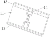
图2为本实用新型磁吸板与磁吸条连接整体结构示意图;Figure 2 is a schematic diagram of the overall structure of the connection between the magnetic plate and the magnetic strip of the present invention;
图3为本实用新型图1中A处放大结构示意图;Fig. 3 is the schematic diagram of enlarged structure at A place in Fig. 1 of the utility model;
图4为本实用新型第一立柱与第二立柱连接俯视剖面结构示意图;Fig. 4 is a schematic cross-sectional structure schematic diagram of the connection between the first column and the second column of the utility model;
图5为本实用新型图2中磁吸条与乐谱本体连接状态侧视结构示意图。Fig. 5 is a side view structural diagram of the connection state between the magnetic strip and the musical score body in Fig. 2 of the present invention.
图中:1、第一立柱;2、第二立柱;3、衔接柱;4、从动轮;5、主动轮;6、转块;7、第一固定板;8、脚架;9、第二固定板;10、连接块;11、放置板;12、固定条;13、磁吸板;14、磁吸条;15、限位块;16、支撑杆。In the figure: 1, the first column; 2, the second column; 3, connecting column; 4, driven wheel; 5, driving wheel; 6, turn block; 7, the first fixed plate; 8, tripod; 9, the second 2. Fixed plate; 10. Connecting block; 11. Placement plate; 12. Fixing bar; 13. Magnetic plate; 14. Magnetic bar; 15. Limiting block;
具体实施方式Detailed ways
下面将结合本实用新型实施例中的附图,对本实用新型实施例中的技术方案进行清楚、完整地描述,显然,所描述的实施例仅仅是本实用新型一部分实施例,而不是全部的实施例。基于本实用新型中的实施例,本领域普通技术人员在没有做出创造性劳动前提下所获得的所有其他实施例,都属于本实用新型保护的范围。The technical solutions in the embodiments of the present invention will be clearly and completely described below in conjunction with the accompanying drawings in the embodiments of the present invention. Obviously, the described embodiments are only part of the embodiments of the present invention, not all of them. example. Based on the embodiments of the present utility model, all other embodiments obtained by persons of ordinary skill in the art without making creative efforts belong to the scope of protection of the present utility model.
请参阅图1-5,本实用新型提供一种技术方案:一种可平铺的乐谱支撑架,包括:第一立柱1的内部设置有第二立柱2,且第二立柱2的内部连接有衔接柱3,并且衔接柱3的上端固定连接有从动轮4,从动轮4的左端连接有主动轮5,且主动轮5的左端固定连接有转块6,第一固定板7固定安装于第二立柱2的下端,第一固定板7的下端固定连接有起到支撑作用的脚架8,第二固定板9固定连接在第一立柱1的上端,第二固定板9的左端连接有支撑杆16,且第二固定板9的右端连接有连接块10,连接块10的右端固定连接有放置板11,且放置板11的右端面下侧位置固定连接有固定条12,磁吸板13固定连接在放置板11的上端,磁吸板13的右端面转动连接有磁吸条14,放置板11的左端面固定连接有限位块15。Please refer to Figures 1-5, the utility model provides a technical solution: a music score support frame that can be tiled, including: the inside of the
在使用该可平铺的乐谱支撑架时,首先将乐谱放置在放置板11的右端面,通过固定条12对乐谱起到支撑作用,具体的如图1、图2和图5中所示,由于磁吸条14关于放置板11的竖直中心线前后对称设置,且磁吸条14的竖截面呈“凹”字型设置,转动磁吸条14,使磁吸条14对乐谱进行铺平,当磁吸条14旋转至水平位置时,通过磁吸条14与磁吸板13吸附连接,对乐谱上端进行压平限位;When using this tileable musical score support frame, firstly the musical score is placed on the right end face of the
具体的如图1中所示,通过连接块10和支撑杆16均与第二固定板9构成转动连接,且限位块15在放置板11的左端面从上至下等间距分布,转动支撑杆16,调节支撑杆16与限位块15的连接位置,即可调整放置板11的倾斜角度,结合图1、图3与图4中所示,通过第二立柱2的竖截面呈矩形设置,且第二立柱2与衔接柱3之间构成螺纹连接,并且从动轮4与主动轮5之间啮合连接,转动转块6带动主动轮5旋转,即可使主动轮5带动从动轮4旋转,通过从动轮4带动衔接柱3在第二立柱2的内部旋转,进而使第二立柱2在第一立柱1的内部上下滑动,从而能够调节该装置的支撑高度,这就是该可平铺的乐谱支撑架的使用方法。Specifically as shown in Fig. 1, both the connecting
本实用新型使用到的标准零件均可以从市场上购买,异形件根据说明书的和附图的记载均可以进行订制,各个零件的具体连接方式均采用现有技术中成熟的螺栓、铆钉、焊接等常规手段,机械、零件和设备均采用现有技术中,常规的型号,加上电路连接采用现有技术中常规的连接方式,在此不再详述,本说明书中未作详细描述的内容属于本领域专业技术人员公知的现有技术。The standard parts used in the utility model can be purchased from the market, and the special-shaped parts can be customized according to the instructions and the records of the drawings. The specific connection methods of each part adopt mature bolts, rivets, welding Conventional means, machinery, parts and equipment all adopt the conventional models in the prior art, and the circuit connection adopts the conventional connection methods in the prior art, which will not be described in detail here, and the content that is not described in detail in this manual Belong to the prior art known to those skilled in the art.
尽管参照前述实施例对本实用新型进行了详细的说明,对于本领域的技术人员来说,其依然可以对前述各实施例所记载的技术方案进行修改,或者对其中部分技术特征进行等同替换,凡在本实用新型的精神和原则之内,所作的任何修改、等同替换、改进等,均应包含在本实用新型的保护范围之内。Although the utility model has been described in detail with reference to the aforementioned embodiments, those skilled in the art can modify the technical solutions described in the aforementioned embodiments, or perform equivalent replacements for some of the technical features. Within the spirit and principles of the utility model, any modification, equivalent replacement, improvement, etc., should be included in the protection scope of the utility model.
Claims (6)
Priority Applications (1)
| Application Number | Priority Date | Filing Date | Title |
|---|---|---|---|
| CN202222029336.3U CN217906778U (en) | 2022-08-03 | 2022-08-03 | Music book support frame that can tile |
Applications Claiming Priority (1)
| Application Number | Priority Date | Filing Date | Title |
|---|---|---|---|
| CN202222029336.3U CN217906778U (en) | 2022-08-03 | 2022-08-03 | Music book support frame that can tile |
Publications (1)
| Publication Number | Publication Date |
|---|---|
| CN217906778U true CN217906778U (en) | 2022-11-29 |
Family
ID=84152801
Family Applications (1)
| Application Number | Title | Priority Date | Filing Date |
|---|---|---|---|
| CN202222029336.3U Expired - Fee Related CN217906778U (en) | 2022-08-03 | 2022-08-03 | Music book support frame that can tile |
Country Status (1)
| Country | Link |
|---|---|
| CN (1) | CN217906778U (en) |
-
2022
- 2022-08-03 CN CN202222029336.3U patent/CN217906778U/en not_active Expired - Fee Related
Similar Documents
| Publication | Publication Date | Title |
|---|---|---|
| CN201084441Y (en) | Display support | |
| CN215501752U (en) | A vocal training aid | |
| CN207893375U (en) | A kind of teaching platform of electronic whiteboard | |
| CN112021780A (en) | A music stand for music teaching with multi-angle adjustment | |
| CN211048725U (en) | Sand paintings art design creation platform | |
| CN210020991U (en) | Integrative training ware of lower waist leg pressing | |
| CN218671308U (en) | VR display screen automatic regulating apparatus | |
| CN218386453U (en) | Cable laying support | |
| CN207397519U (en) | Display rack for network holographic projection teaching | |
| CN211669807U (en) | Manpower resource teaching device | |
| CN211294465U (en) | A model display stand for teaching mechanical design | |
| CN211885104U (en) | An easily adjustable high jump frame for sports training | |
| CN211984334U (en) | Combined office table | |
| CN211065483U (en) | Multifunctional learning table for drawing education | |
| CN211015000U (en) | Multifunctional projection screen support | |
| CN221222192U (en) | A display support frame | |
| CN209662585U (en) | Prompting device for dance professional practice | |
| CN219210018U (en) | Lifting platform for physics experiment | |
| CN220554416U (en) | A reversible table | |
| CN219249734U (en) | Medical model show stand convenient to dismantle | |
| CN221888636U (en) | Adjustable delivery bed | |
| CN222303372U (en) | Adjustable auxiliary device for vocal music training | |
| CN221279087U (en) | A vertically adjustable display | |
| CN218686159U (en) | A basketball stand that is convenient for adaptive adjustment | |
| CN214541459U (en) | Display board mounting structure |
Legal Events
| Date | Code | Title | Description |
|---|---|---|---|
| GR01 | Patent grant | ||
| GR01 | Patent grant | ||
| TR01 | Transfer of patent right | ||
| TR01 | Transfer of patent right |
Effective date of registration: 20230508 Address after: 161006, No. 42, culture street, Jianhua District, Heilongjiang, Qigihar Patentee after: QIQIHAR University Address before: 161000 building 23, West District, Dongshi District, Jianhua District, Qiqihar City, Heilongjiang Province Patentee before: Wu Guihua |
|
| CF01 | Termination of patent right due to non-payment of annual fee | ||
| CF01 | Termination of patent right due to non-payment of annual fee |
Granted publication date: 20221129 |