CN217896185U - Bent cap construction structures - Google Patents
Bent cap construction structures Download PDFInfo
- Publication number
- CN217896185U CN217896185U CN202221043784.2U CN202221043784U CN217896185U CN 217896185 U CN217896185 U CN 217896185U CN 202221043784 U CN202221043784 U CN 202221043784U CN 217896185 U CN217896185 U CN 217896185U
- Authority
- CN
- China
- Prior art keywords
- positioning
- fixed
- supporting
- support
- pier
- Prior art date
- Legal status (The legal status is an assumption and is not a legal conclusion. Google has not performed a legal analysis and makes no representation as to the accuracy of the status listed.)
- Active
Links
Images




Classifications
-
- Y—GENERAL TAGGING OF NEW TECHNOLOGICAL DEVELOPMENTS; GENERAL TAGGING OF CROSS-SECTIONAL TECHNOLOGIES SPANNING OVER SEVERAL SECTIONS OF THE IPC; TECHNICAL SUBJECTS COVERED BY FORMER USPC CROSS-REFERENCE ART COLLECTIONS [XRACs] AND DIGESTS
- Y02—TECHNOLOGIES OR APPLICATIONS FOR MITIGATION OR ADAPTATION AGAINST CLIMATE CHANGE
- Y02E—REDUCTION OF GREENHOUSE GAS [GHG] EMISSIONS, RELATED TO ENERGY GENERATION, TRANSMISSION OR DISTRIBUTION
- Y02E10/00—Energy generation through renewable energy sources
- Y02E10/20—Hydro energy
Landscapes
- Bridges Or Land Bridges (AREA)
Abstract
本实用新型中公开了一种盖梁施工结构,包括设置在墩柱上的支撑构件,所述支撑构件在墩柱上水平朝外伸出设置,位于同一侧的相邻两个支撑构件之间分别设置有支撑梁,位于支撑梁上设置有支架支撑结构;所述支撑构件包括预埋在墩柱内的固定爬锥、定位爬锥和牛腿,所述牛腿通过固定爬锥和定位爬锥固定安装在墩柱上,所述固定爬锥和定位爬锥沿墩柱轴向方向设置于同一直线上。本实用新型的盖梁施工结构中,采用爬锥与牛腿组合的支撑构件能够对盖梁施工支架提供稳定的支撑,在方便施工的同时,能够提高盖梁施工的安全性。通过对爬锥的设置进行优化布置,在保证牛腿整体结构强度的同时,并能够尽可能地减小爬锥拆除后对墩柱结构所造成的影响。
The utility model discloses a construction structure of a cover beam, which includes a support member arranged on a pier column, and the support member is horizontally extended outward on the pier column, and is located between two adjacent support members on the same side. Supporting beams are provided respectively, and a bracket supporting structure is arranged on the supporting beams; the supporting members include fixed climbing cones, positioning climbing cones and corbels embedded in the pier columns, and the corbels pass through the fixed climbing cones and positioning climbing cones. Fixedly installed on the pier column, the fixed climbing cone and the positioning climbing cone are arranged on the same straight line along the axial direction of the pier column. In the construction structure of the cover beam of the utility model, the support member combined with the climbing cone and the corbel can provide stable support for the construction support of the cover beam, which can improve the safety of the construction of the cover beam while facilitating construction. By optimizing the setting of the climbing cones, while ensuring the overall structural strength of the corbel, the impact on the pier structure after the climbing cones are removed can be minimized as much as possible.
Description
技术领域technical field
本实用新型涉及桥梁施工技术领域,特别涉及一种盖梁施工结构。The utility model relates to the technical field of bridge construction, in particular to a cover beam construction structure.
背景技术Background technique
盖梁施工是桥梁施工中不可缺少的施工工序,桥墩盖梁支架是盖梁现浇过程中载荷的承受体,是模板安装的平台以及现浇操作的施工平台。目前国内在盖梁施工中对于盖梁支架的支撑通常采用的是穿心棒法或抱箍法;采用穿心棒法需要在墩柱上预设穿心通孔,导致容易对墩身结构造成破坏;而抱箍通常只适用于圆形墩柱,且其主要依靠与墩柱之间的摩擦力来维持其上部的载荷,因此存在较大的安全隐患。Cover beam construction is an indispensable construction process in bridge construction. The bridge pier cover beam support is the load bearing body during the process of casting the cover beam, and it is the platform for the formwork installation and the construction platform for the cast-in-place operation. At present, in the construction of cap beams in China, the support of the cap beam bracket is usually the piercing rod method or the hoop method; using the piercing rod method requires preset piercing holes on the pier column, which will easily cause damage to the pier body structure; The hoop is usually only suitable for circular piers, and it mainly relies on the friction between the piers to maintain the load on its upper part, so there is a big safety hazard.
实用新型内容Utility model content
本实用新型提供一种盖梁施工结构,以有效解决现有盖梁施工结构容易对墩身造成破坏、存在安全隐患的问题。The utility model provides a cover beam construction structure to effectively solve the problems that the existing cover beam construction structure is easy to cause damage to the pier body and has potential safety hazards.
为解决上述技术问题,本实用新型采用的技术方案如下:For solving the problems of the technologies described above, the technical scheme that the utility model adopts is as follows:
一种盖梁施工结构,包括设置在墩柱上的支撑构件,所述支撑构件在墩柱上水平朝外伸出设置,位于同一侧的相邻两个支撑构件之间分别设置有支撑梁,位于支撑梁上设置有支架支撑结构;A cover-beam construction structure, comprising a support member arranged on a pier column, the support member protrudes outward horizontally on the pier column, and a support beam is respectively arranged between two adjacent support members on the same side, A bracket supporting structure is arranged on the supporting beam;
所述支撑构件包括预埋在墩柱内的固定爬锥、定位爬锥和牛腿,所述牛腿通过固定爬锥和定位爬锥固定安装在墩柱上,所述固定爬锥和定位爬锥沿墩柱轴向方向设置于同一直线上。The support member includes a fixed climbing cone, a positioning climbing cone and a corbel embedded in the pier column. The corbel is fixedly installed on the pier column through the fixed climbing cone and the positioning climbing cone. The fixed climbing cone and the positioning climbing cone They are arranged on the same straight line along the axial direction of the piers.
作为上述技术方案的进一步改进,所述墩柱为圆柱墩,所述支撑构件沿墩柱中心对称设置于墩柱两侧,所述支撑构件分别沿与盖梁垂直方向向外伸出设置,所述支撑梁分别搭设在相邻两个墩柱上的支撑构件上,所述支撑梁沿盖梁平行方向设置,所述支架支撑结构包括在支撑梁上沿其纵向方向依次设置的多个支撑横梁。As a further improvement of the above technical solution, the pier column is a cylindrical pier, the support members are symmetrically arranged on both sides of the pier column along the center of the pier column, and the support members are respectively protruded outward along the direction perpendicular to the cover beam, so The supporting beams are set up on the supporting members on two adjacent pier columns respectively, the supporting beams are arranged along the parallel direction of the cover beams, and the supporting structure of the bracket includes a plurality of supporting beams arranged sequentially along the longitudinal direction on the supporting beams.
作为上述技术方案的进一步改进,所述墩柱为过渡墩外空心墩,所述支撑构件沿墩柱中心对称设置于墩柱两侧,所述支撑构件分别沿与盖梁平行的方向向外伸出设置,所述墩柱上沿盖梁横向方向设置有至少两个支撑构件,所述支撑梁分别搭设在位于墩柱同一侧的两个支撑构件上,所述支架支撑结构包括设置于支撑梁上的支撑纵梁和设置于支撑纵梁上的多个搭接梁。As a further improvement of the above technical solution, the pier column is a hollow pier outside the transition pier, the support members are symmetrically arranged on both sides of the pier column along the center of the pier column, and the support members extend outward in a direction parallel to the cover beam Out of the setting, at least two support members are arranged on the pier column along the transverse direction of the cover beam, and the support beams are respectively erected on the two support members on the same side of the pier column. The upper support stringer and a plurality of overlapping beams arranged on the support stringer.
作为上述技术方案的进一步改进,所述牛腿包括连接板、支撑板和设置于连接板两侧的加强板,所述连接板上位于加强板之间分别设置有固定孔和定位孔,所述定位孔为沿墩柱轴向方向设置的条形孔。As a further improvement of the above technical solution, the corbel includes a connecting plate, a supporting plate and reinforcing plates arranged on both sides of the connecting plate, and the connecting plate is respectively provided with fixing holes and positioning holes between the reinforcing plates. The positioning hole is a strip hole arranged along the axial direction of the pier column.
作为上述技术方案的进一步改进,所述固定爬锥包括固定爬锥体和设置在固定爬锥体一端的固定连接筋,所述固定爬锥体另一端设置有用于连接固定螺栓的固定螺孔,所述固定螺孔直径大于固定连接筋直径。As a further improvement of the above technical solution, the fixed climbing cone includes a fixed climbing cone and a fixed connecting rib arranged at one end of the fixed climbing cone, and the other end of the fixed climbing cone is provided with a fixing screw hole for connecting a fixing bolt, The diameter of the fixing screw hole is larger than the diameter of the fixing connecting rib.
作为上述技术方案的进一步改进,所述固定螺孔的深度不小于墩柱混凝土保护层厚度。As a further improvement of the above technical solution, the depth of the fixing screw hole is not less than the thickness of the pier concrete protective layer.
作为上述技术方案的进一步改进,所述定位爬锥包括定位爬锥体、设置在定位爬锥体一端的定位连接筋和设置在定位连接筋上的定位件,所述定位爬锥体另一端设置有用于连接定位螺栓的定位螺孔,所述定位螺孔直径大于定位连接筋直径。As a further improvement of the above technical solution, the positioning climbing cone includes a positioning climbing cone, a positioning connecting rib arranged at one end of the positioning climbing cone and a positioning piece arranged on the positioning connecting rib, and the other end of the positioning climbing cone is provided There are positioning screw holes for connecting the positioning bolts, and the diameter of the positioning screw holes is larger than the diameter of the positioning connecting ribs.
作为上述技术方案的进一步改进,所述固定爬锥体与定位爬锥体均为圆锥台结构,所述固定爬锥体的径向尺寸大于定位爬锥体的径向尺寸。As a further improvement of the above technical solution, both the fixed climbing cone and the positioning climbing cone have a frustum of conical structure, and the radial dimension of the fixed climbing cone is larger than the radial dimension of the positioning climbing cone.
作为上述技术方案的进一步改进,位于牛腿与支撑梁之间设置有垫板,所述支撑梁设置在垫板上,所述垫板与牛腿之间在横梁外侧设置有用于连接垫板与牛腿的连接件,所述连接件突出垫板表面设置。As a further improvement of the above technical solution, a backing plate is provided between the corbel and the support beam, the support beam is set on the backing plate, and a device for connecting the backing plate and the cross beam is provided between the backing plate and the corbel on the outside of the beam. The connecting part of the corbel, the connecting part protrudes from the surface of the backing plate.
本实用新型的盖梁施工结构中,采用爬锥与牛腿组合的支撑构件能够对盖梁施工支架提供稳定的支撑,在方便施工的同时,能够提高盖梁施工的安全性。In the construction structure of the cover beam of the utility model, the support member combined with the climbing cone and the corbel can provide stable support for the construction support of the cover beam, which can improve the safety of the construction of the cover beam while facilitating construction.
通过对爬锥的设置进行优化布置,每个牛腿仅采用两个爬锥进行固定,在保证牛腿整体结构强度的同时,能够方便爬锥在墩柱内的预埋施工,以及牛腿与爬锥之间的配合安装,并能够尽可能地减小爬锥拆除后对墩柱结构所造成的影响。By optimizing the arrangement of the climbing cones, each corbel is fixed with only two climbing cones, which can facilitate the pre-embedded construction of the climbing cones in the pier column while ensuring the overall structural strength of the corbel, and the connection between the corbel and the The cooperative installation between the climbing cones can minimize the impact on the pier structure after the climbing cones are removed.
附图说明Description of drawings
为了更清楚地说明本实用新型实施例的技术方案,下面将对实施例中的附图作简单地介绍,应当理解,以下附图仅示出了本实用新型的某些实施例,因此不应被看作是对范围的限定,对于本领域普通技术人员来讲,在不付出创造性劳动的前提下,还可以根据这些附图获得其他相关的附图。In order to more clearly illustrate the technical solutions of the embodiments of the utility model, the accompanying drawings in the embodiments will be briefly introduced below. It should be understood that the following drawings only show some embodiments of the utility model, and therefore should not It is regarded as a limitation on the scope, and those skilled in the art can also obtain other related drawings based on these drawings without creative work.
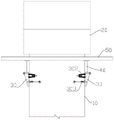
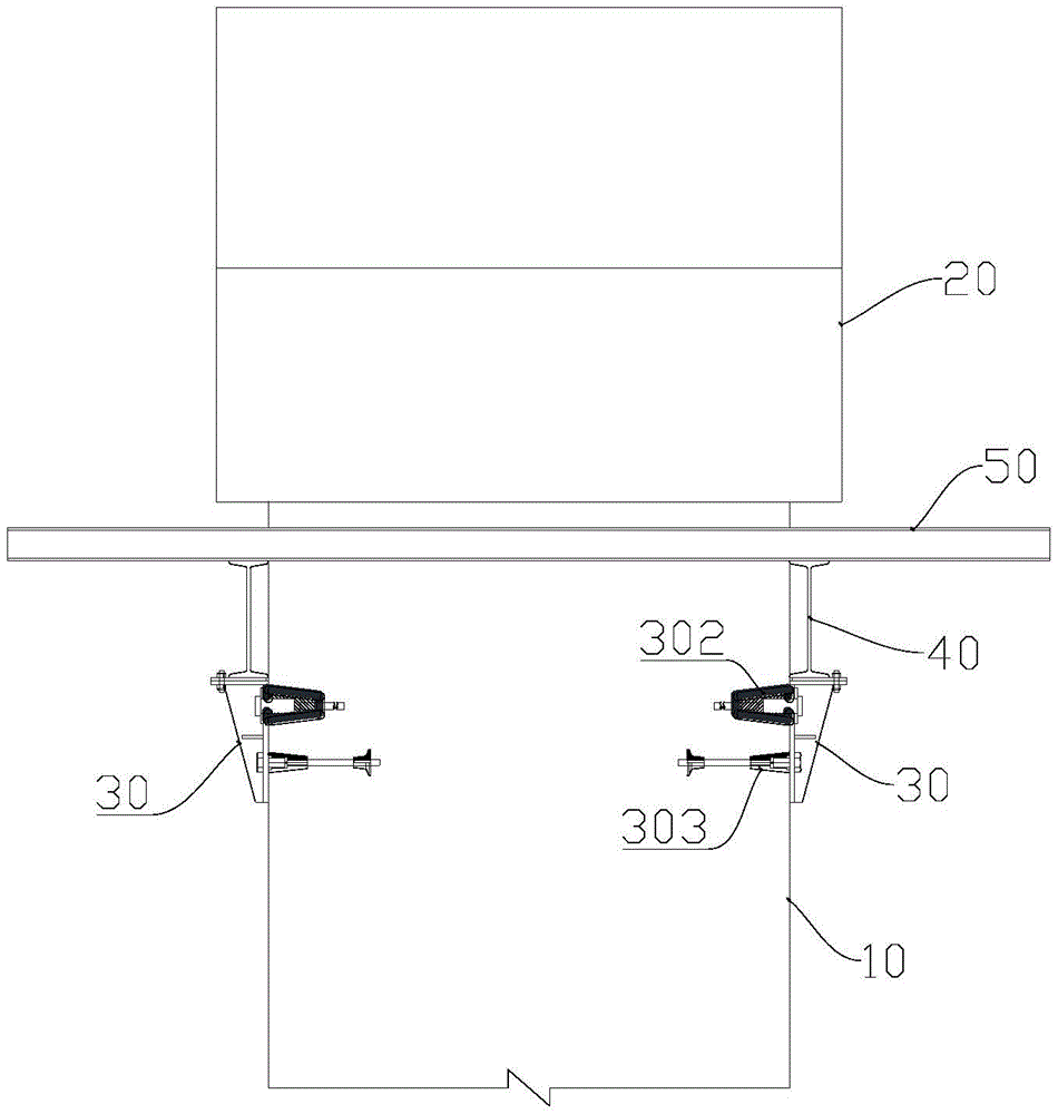
图1为本实用新型盖梁施工结构一种实施方式结构主视图。Fig. 1 is a structural front view of an embodiment of the utility model cover beam construction structure.
图2为本实用新型盖梁施工结构一种实施方式结构侧视图。Fig. 2 is a structural side view of an embodiment of the utility model cover beam construction structure.
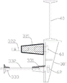
图3为本实用新型盖梁施工结构中牛腿结构示意图。Fig. 3 is a schematic diagram of the corbel structure in the construction structure of the utility model cover beam.
图4为本实用新型盖梁施工结构中支撑构件结构示意图。Fig. 4 is a structural schematic diagram of the support member in the construction structure of the utility model cover beam.
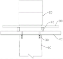
图5为本实用新型盖梁施工结构另一实施方式结构主视图。Fig. 5 is a structural front view of another embodiment of the construction structure of the cover beam of the present invention.
图6为本实用新型盖梁施工结构另一实施方式结构侧视图。Fig. 6 is a side view of another embodiment of the construction structure of the cover beam of the present invention.
图7为本实用新型盖梁施工结构另一实施方式中牛腿在墩柱上的连接结构示意图。Fig. 7 is a schematic diagram of the connection structure of the corbel on the pier column in another embodiment of the construction structure of the cover beam of the present invention.
图中:10、墩柱,20、盖梁;Among the figure: 10, pier column, 20, cover beam;
30、支撑构件,301、牛腿,311、连接板,312、支撑板,313、加强板,314、固定孔,315、定位孔,302、固定爬锥,321、固定爬锥体,322、固定连接筋,303、定位爬锥,331、定位爬锥体,332、定位连接筋,333、定位件;30, support member, 301, corbel, 311, connecting plate, 312, support plate, 313, reinforcing plate, 314, fixing hole, 315, positioning hole, 302, fixing climbing cone, 321, fixing climbing cone, 322, Fixed connecting rib, 303, positioning climbing cone, 331, positioning climbing cone, 332, positioning connecting rib, 333, positioning piece;
40、支撑梁,50、支撑横梁;40, support beam, 50, support beam;
61、固定螺栓,62、定位螺栓,63、垫板,64、连接件;61, fixing bolts, 62, positioning bolts, 63, backing plate, 64, connectors;
70、支撑纵梁,80、搭接梁;70, support stringer, 80, lap beam;
91、芯棒,92、支撑件。91, mandrel, 92, support.
具体实施方式Detailed ways
为使本实用新型实施例的目的、技术方案和优点更加清楚,下面将结合本实用新型实施例中的附图,对本实用新型实施例中的技术方案进行清楚、完整地描述,显然,所描述的实施例是本实用新型一部分实施例,而不是全部的实施例。In order to make the purpose, technical solutions and advantages of the embodiments of the utility model more clear, the technical solutions in the embodiments of the utility model will be clearly and completely described below in conjunction with the accompanying drawings in the embodiments of the utility model. Obviously, the described The embodiments are some embodiments of the present utility model, but not all embodiments.
实施例一Embodiment one
参照图1和2,以墩柱10为圆柱墩为例,对本实施例中的盖梁施工结构进行说明。Referring to Figures 1 and 2, taking the
本实施例中的盖梁施工结构包括设置在墩柱10上的支撑构件30,支撑构件30在墩柱10上水平朝外伸出设置,位于同一侧的相邻两个支撑构件30之间分别设置支撑梁40,位于支撑梁40上设置施工支撑结构,用于搭设盖梁施工支架。The cover beam construction structure in this embodiment includes a
针对圆柱墩上盖梁的施工特点,这里支撑构件30沿墩柱中心对称设置于墩柱10两侧,两侧的支撑构件30位于墩柱10上同一水平面上的同一直径方向上;同一墩柱10上的两个支撑构件30分别沿与盖梁20垂直的方向向外伸出设置,此时支撑梁40分别搭设在相邻两个墩柱上的支撑构件30上,使支撑梁40沿盖梁平行方向设置分别设置于盖梁20的两侧。此时,在支撑梁40上搭设的支架支撑结构包括在支撑梁上沿其纵向方向依次设置的多个支撑横梁50,支撑横梁50在支撑梁40上间隔设置,用于为盖梁施工之间提供稳定的搭设平台。In view of the construction characteristics of the upper cover beam of the cylindrical pier, the
如图4,本实施例中支撑构件30包括预埋在墩柱内的固定爬锥302、定位爬锥303和牛腿301,固定爬锥302和定位爬锥303预埋固定设置于墩柱10内,在固定爬锥302、定位爬锥303的预埋施工时,以墩柱为中心,同步吊装分别设置于两侧的固定爬锥、定位爬锥,使两侧的固定爬锥、定位爬锥位于同一水平面上,位于同一侧的固定爬锥与定位爬锥位于同一竖直直线上,以保证两侧牛腿安装的位置精度。As shown in Fig. 4, the
通过固定螺栓和固定爬锥将牛腿固定安装到墩柱上,通过定位螺栓和定位爬锥对牛腿在墩柱上定位安装,防止牛腿在墩柱上发生转动。通过在墩柱上预埋两个爬锥即可实现对牛腿的固定安装,结构简单方便现场的安装和后期拆卸;且采用预埋爬锥的结构,在施工完毕后在墩柱上只会留下爬锥尺寸大小的孔洞,能够很好地保证墩柱的完整性,不会对墩柱造成影响。The corbel is fixedly installed on the pier column through the fixing bolt and the fixed climbing cone, and the corbel is positioned and installed on the pier column through the positioning bolt and the positioning climbing cone to prevent the corbel from rotating on the pier column. The fixed installation of the corbel can be realized by pre-burying two climbing cones on the pier column. The structure is simple and convenient for on-site installation and later disassembly; Leaving a hole of the size of the climbing cone can well ensure the integrity of the pier and will not affect the pier.
如图3,本实施例中的牛腿301包括连接板311、支撑板312和设置于连接板两侧的加强板313,连接板311上位于加强板之间分别设置有固定孔314和定位孔315,定位孔315为沿墩柱轴向方向设置的条形孔。水平设置的支撑板312为支撑梁的设置提供支撑安装的平台,加强板313设置在连接板和支撑板之间提高牛腿的整体结构强度,在固定孔314和定位孔315内分别设置固定螺栓61和定位螺栓62,用于将牛腿301与固定爬锥302和定位爬锥303之间固定连接,将牛腿固定安装到墩柱上。As shown in Figure 3, the
在固定爬锥的设置上,固定爬锥302包括固定爬锥体321和设置在固定爬锥体一端的固定连接筋322,固定爬锥体302的另一端设置用于连接固定螺栓的固定螺孔,固定螺孔的直径大于固定连接筋322直径。In the setting of the fixed climbing cone, the fixed
在定位爬锥的设置上,定位爬锥303包括定位爬锥体331、设置在定位爬锥体331一端的定位连接筋332和设置在定位连接筋上的定位件333,定位爬锥体331另一端设置用于连接定位螺栓的定位螺孔,定位螺孔直径大于定位连接筋332直径。In the setting of the positioning and climbing cone, the positioning and
在对爬锥的结构设置上,根据盖梁施工支架的施工要求,固定爬锥体321与定位爬锥体331均为圆锥台结构,固定爬锥体321的径向尺寸大于定位爬锥体331的径向尺寸。具体地,固定爬锥作为牛腿的主要固定承力部件,固定爬锥体321的大端直径为120mm,小端直径为70mm,长为200mm,采用45钢制成;定位爬锥作为对牛腿的辅助承力部件以及定位功能部件,定位爬锥体331的大端直径为68mm,小端直径为40mm,采用45钢制成。固定爬锥体上固定螺孔规格为M56,对应的固定螺栓直径为56mm,采用40Cr制成;定位爬锥体上定位螺孔规格为M36,对应的定位螺栓之间为36mm,采用40Cr制成,以保证牛腿在墩柱上足够的连接强度。In terms of the structural setting of the climbing cone, according to the construction requirements of the construction support of the cover beam, the fixed
固定爬锥体321上固定螺纹孔的深度设置为不小于墩柱混凝土保护层厚度,使牛腿安装时固定螺栓的连接长度不小于混凝土保护层厚度,以保证施工完成拆除爬锥后墩柱混凝土保护层内无铁件,以减小对墩柱结构的影响。The depth of the fixed threaded hole on the fixed
如图3,在位于牛腿301的支撑板与支撑梁之间设置垫板63,支撑梁40设置在垫板63上,垫板63与支撑板312之间在横梁外侧设置用于连接垫板与支撑板的连接件64,将垫板固定设置在支撑板上;连接件可采用双头螺栓和螺母结构,连接件端部突出垫板表面设置,在连接支撑板与垫板的同时,突出的连接件能够起到对支撑梁限位的作用。As shown in Figure 3, a
此时在相邻两个墩柱上的牛腿上分别设置支撑梁,在支撑梁上搭设支撑横梁,即可快速完成支撑平台的搭设,为盖梁施工支架提供稳定的支撑平台。At this time, support beams are respectively set on the corbels on two adjacent pier columns, and support beams are set up on the support beams to quickly complete the erection of the support platform and provide a stable support platform for the construction support of the cover beam.
实施例二Embodiment two
参照图5和6,以过渡墩外空心墩上盖梁的施工为例,对本实施例中的盖梁施工结构进行说明。Referring to Figures 5 and 6, taking the construction of the cover beam on the hollow pier outside the transition pier as an example, the construction structure of the cover beam in this embodiment will be described.
在该实施例中墩柱10为过渡墩外空心墩,支撑构件30沿墩柱中心对称设置于墩柱两侧,支撑构件30分别沿与盖梁平行的方向向外伸出设置,墩柱10上位于其一侧沿盖梁横向方向设置两个支撑构件30,支撑梁40分别搭设在位于墩柱同一侧的两个支撑构件30上。支架支撑结构包括设置于支撑梁上的支撑纵梁70和设置于支撑纵梁上的多个搭接梁80,形成稳定的盖梁施工支架支撑平台。In this embodiment, the
参照图7,这种结构形式的盖梁施工结构中,墩柱10一侧的支撑构件中可采用两个定位爬锥303对牛腿进行固定,采用两个小规格的爬锥结构,减小爬锥拆除后对墩柱结构的影响。为保证该位置处牛腿的结构强度,牛腿301下方位置设置穿设在墩柱上的芯棒91,在芯棒91与牛腿301之间设置折板结构的支撑件92,对牛腿提供辅助支撑,在完成施工后拆除芯棒和支撑件,盖梁施工结构整体结构稳定,安装和拆除方便。Referring to Fig. 7, in the cap beam construction structure of this structure, two
在本实用新型的描述中,需要说明的是,所采用的术语“中心”、“上”、“下”、“左”、“右”、“竖直”、“水平”、“内”、“外”等指示的方位或位置关系为基于附图所示的方位或位置关系,或者是该实用新型产品使用时惯常摆放的方位或位置关系,仅是为了便于描述本实用新型和简化描述,而不是指示或暗示所指的装置或元件必须具有特定的方位、以特定的方位构造和操作,因此不能理解为对本实用新型的限制。In the description of the present utility model, it should be noted that the terms "center", "upper", "lower", "left", "right", "vertical", "horizontal", "inner", The orientation or positional relationship indicated by "outside" is based on the orientation or positional relationship shown in the drawings, or the orientation or positional relationship that is usually placed when the product of this utility model is used, and is only for the convenience of describing the utility model and simplifying the description , rather than indicating or implying that the device or element referred to must have a specific orientation, be constructed and operated in a specific orientation, and therefore should not be construed as limiting the utility model.
此外,本实用新型的描述中若出现“水平”、“竖直”等术语并不表示要求部件绝对水平或悬垂,而是可以稍微倾斜。如“水平”仅仅是指其方向相对“竖直”而言更加水平,并不是表示该结构一定要完全水平,而是可以稍微倾斜。In addition, terms such as "horizontal" and "vertical" in the description of the utility model do not mean that the components are required to be absolutely horizontal or hang, but may be slightly inclined. For example, "horizontal" only means that its direction is more horizontal than "vertical", and it does not mean that the structure must be completely horizontal, but can be slightly inclined.
在本实用新型的描述中,还需要说明的是,除非另有明确的规定和限定,若出现术语“设置”、“安装”、“相连”、“连接”应做广义理解,例如,可以是固定连接,也可以是可拆卸连接,或一体地连接;可以是机械连接,也可以是电连接;可以是直接相连,也可以通过中间媒介间接相连,可以是两个元件内部的连通。对于本领域的普通技术人员而言,可以具体情况理解上述术语在本实用新型中的具体含义。In the description of the present utility model, it should also be noted that, unless otherwise specified and limited, if the terms "setting", "installation", "connection" and "connection" appear, they should be understood in a broad sense, for example, it can be A fixed connection can also be a detachable connection or an integral connection; it can be a mechanical connection or an electrical connection; it can be a direct connection or an indirect connection through an intermediary, and it can be the internal communication of two components. Those of ordinary skill in the art can understand the specific meanings of the above terms in the present utility model in specific situations.
以上所述仅为本实用新型的优选实施例而已,并不用于限制本实用新型,对于本领域的技术人员来说,本实用新型可以有各种更改和变化。凡在本实用新型的精神和原则之内,所作的任何修改、等同替换、改进等,均应包含在本实用新型的保护范围之内。The above descriptions are only preferred embodiments of the utility model, and are not intended to limit the utility model. For those skilled in the art, the utility model can have various modifications and changes. Any modification, equivalent replacement, improvement, etc. made within the spirit and principles of the present utility model shall be included in the protection scope of the present utility model.
Claims (9)
Priority Applications (1)
| Application Number | Priority Date | Filing Date | Title |
|---|---|---|---|
| CN202221043784.2U CN217896185U (en) | 2022-04-29 | 2022-04-29 | Bent cap construction structures |
Applications Claiming Priority (1)
| Application Number | Priority Date | Filing Date | Title |
|---|---|---|---|
| CN202221043784.2U CN217896185U (en) | 2022-04-29 | 2022-04-29 | Bent cap construction structures |
Publications (1)
| Publication Number | Publication Date |
|---|---|
| CN217896185U true CN217896185U (en) | 2022-11-25 |
Family
ID=84110803
Family Applications (1)
| Application Number | Title | Priority Date | Filing Date |
|---|---|---|---|
| CN202221043784.2U Active CN217896185U (en) | 2022-04-29 | 2022-04-29 | Bent cap construction structures |
Country Status (1)
| Country | Link |
|---|---|
| CN (1) | CN217896185U (en) |
Cited By (1)
| Publication number | Priority date | Publication date | Assignee | Title |
|---|---|---|---|---|
| CN117513163A (en) * | 2023-11-10 | 2024-02-06 | 湖南路桥建设集团有限责任公司 | Support platform and construction method for cylindrical pier cap beam and middle tie beam construction |
-
2022
- 2022-04-29 CN CN202221043784.2U patent/CN217896185U/en active Active
Cited By (1)
| Publication number | Priority date | Publication date | Assignee | Title |
|---|---|---|---|---|
| CN117513163A (en) * | 2023-11-10 | 2024-02-06 | 湖南路桥建设集团有限责任公司 | Support platform and construction method for cylindrical pier cap beam and middle tie beam construction |
Similar Documents
| Publication | Publication Date | Title |
|---|---|---|
| CN103452311B (en) | A kind of erection method of shaped steel suspended structural support frame | |
| CN209163516U (en) | A kind of post-cast strip tool support device | |
| CN108999394B (en) | Construction process of floor type scaffold rotary cantilever type scaffold | |
| CN103243900B (en) | Wall connecting assembly of steel pipe scaffold | |
| CN209468865U (en) | A kind of isolated footing foundation bolt integral built-in positioning reinforcing device | |
| CN103205927A (en) | Anti-overturning bridge pier supporting mechanism | |
| CN214658863U (en) | Long inclined plane fair-faced concrete formwork support system with inclination angle larger than 45 degrees | |
| CN204282803U (en) | To encorbelment formwork structure for mounting platform | |
| CN215291438U (en) | Post-cast with independent support structure | |
| CN216551573U (en) | Built-in steel tower column splicing construction assembly structure | |
| CN103132494A (en) | Embedded anchor cone accurate positioning method | |
| CN210396103U (en) | A connector, external wall panel and shear wall formwork system for shear wall formwork system | |
| CN216947881U (en) | Formwork support of I-shaped composite beam cast-in-situ bridge deck | |
| CN110847189A (en) | An assembled foundation pit column underpinning structure | |
| CN214246565U (en) | Scaffold support platform and high-altitude large-span beam formwork support system | |
| CN210828340U (en) | C-shaped reinforcing member | |
| CN215055273U (en) | A assembled template for installing support bracket embedded box | |
| CN115652800A (en) | Steel box girder traction rapid construction method | |
| CN211850773U (en) | A kind of external wall scaffolding connecting wall | |
| CN209243920U (en) | A connection node for prefabricated components | |
| CN207999058U (en) | A kind of key slot type Multi-functional top bracket | |
| CN108385963B (en) | A keyway type multifunctional jacking support | |
| CN223661339U (en) | An adjustable support for erecting scaffolding on a steep slope | |
| CN206267039U (en) | A kind of jack support platform of hollow slab girder jack-up construction | |
| CN223293385U (en) | A tie-rod-free single-sided cantilever formwork support structure |
Legal Events
| Date | Code | Title | Description |
|---|---|---|---|
| GR01 | Patent grant | ||
| GR01 | Patent grant |