CN217895117U - High-precision full-automatic filling machine - Google Patents
High-precision full-automatic filling machine Download PDFInfo
- Publication number
- CN217895117U CN217895117U CN202222427061.9U CN202222427061U CN217895117U CN 217895117 U CN217895117 U CN 217895117U CN 202222427061 U CN202222427061 U CN 202222427061U CN 217895117 U CN217895117 U CN 217895117U
- Authority
- CN
- China
- Prior art keywords
- filling
- storage tank
- valve
- box
- conveying mechanism
- Prior art date
- Legal status (The legal status is an assumption and is not a legal conclusion. Google has not performed a legal analysis and makes no representation as to the accuracy of the status listed.)
- Active
Links
Images


Landscapes
- Basic Packing Technique (AREA)
Abstract
本实用新型公开了一种高精度全自动灌装机,包括支撑台、输送机构、灌装机构、储料罐和升降机构,所述输送机构设置在所述支撑台的上方前侧,所述灌装机构设置在所述输送机构的后侧,所述储料罐设置在所述灌装机构的上方,所述储料罐内设置有超声波液位监测装置,所述升降机构设置在所述灌装机构与所述输送机构之间。本实用新型采用上述结构的一种高精度全自动灌装机,灌装精度高,速度快,便于使用。
The utility model discloses a high-precision full-automatic filling machine, which comprises a supporting platform, a conveying mechanism, a filling mechanism, a material storage tank and a lifting mechanism. The conveying mechanism is arranged on the upper front side of the supporting platform. The filling mechanism is arranged on the rear side of the conveying mechanism, the storage tank is arranged above the filling mechanism, an ultrasonic liquid level monitoring device is arranged in the storage tank, and the lifting mechanism is arranged on the Between the filling mechanism and the conveying mechanism. The utility model adopts a high-precision automatic filling machine with the above-mentioned structure, which has high filling precision, fast speed and is easy to use.
Description
技术领域technical field
本实用新型涉及灌装机设备技术领域,特别是涉及一种高精度全自动灌装机。The utility model relates to the technical field of filling machine equipment, in particular to a high-precision full-automatic filling machine.
背景技术Background technique
灌装机主要是包装机中的一小类产品,从对物料的包装角度可分为液体灌装机,膏体灌装机,粉剂灌装机和颗粒灌装机,从生产的自动化程度来讲分为半自动灌装机和全自动灌装生产线。而现有技术中在对乳液类原料进行灌装时,由于在进行灌装时储存罐中的液面的高度会不断的下降,导致乳液排出的压强下降,流速变慢,导致后期的灌装量减少,对加工精度造成影响,并且在现有技术中在灌装时,乳液类的原料极易喷溅出包装瓶外,造成浪费,影响灌装精度。Filling machines are mainly a small category of products in packaging machines. From the perspective of packaging materials, they can be divided into liquid filling machines, paste filling machines, powder filling machines and granule filling machines. From the degree of automation of production It is divided into semi-automatic filling machine and fully automatic filling production line. In the prior art, when the emulsion raw materials are filled, since the height of the liquid level in the storage tank will continue to drop during filling, the pressure of the emulsion discharge will drop, and the flow rate will slow down, resulting in later stage filling. The amount is reduced, which affects the processing accuracy, and when filling in the prior art, the raw materials of the emulsion are easily splashed out of the packaging bottle, causing waste and affecting the filling accuracy.
实用新型内容Utility model content
本实用新型的目的是提供一种高精度全自动灌装机,灌装精度高,速度快,便于使用。The purpose of the utility model is to provide a high-precision full-automatic filling machine, which has high filling precision, fast speed and is easy to use.
为实现上述目的,本实用新型提供了一种高精度全自动灌装机,包括支撑台、输送机构、灌装机构、储料罐和升降机构,所述输送机构设置在所述支撑台的上方前侧,所述灌装机构设置在所述输送机构的后侧,所述储料罐设置在所述灌装机构的上方,所述储料罐内设置有超声波液位监测装置,所述升降机构设置在所述灌装机构与所述输送机构之间;In order to achieve the above purpose, the utility model provides a high-precision automatic filling machine, including a support platform, a conveying mechanism, a filling mechanism, a storage tank and a lifting mechanism, and the conveying mechanism is arranged above the support platform On the front side, the filling mechanism is arranged on the rear side of the conveying mechanism, the storage tank is arranged above the filling mechanism, an ultrasonic liquid level monitoring device is arranged in the storage tank, and the lifting The mechanism is arranged between the filling mechanism and the conveying mechanism;
所述灌装机构包括转子泵、减速电机、三通球阀、连接管和灌装阀,所述转子泵的一端与所述减速电机连接,所述转子泵远离所述减速电机的一端设置有进料口和出料口,所述进料口与所述储料罐的下料口连接,所述出料口的下方设置有所述三通球阀,所述三通球阀通过所述连接管与所述灌装阀连接,所述灌装阀通过固定块与所述升降机构连接;The filling mechanism includes a rotor pump, a geared motor, a three-way ball valve, a connecting pipe and a filling valve. One end of the rotor pump is connected to the geared motor, and the end of the rotor pump away from the geared motor is provided with an inlet A feed port and a discharge port, the feed port is connected to the discharge port of the storage tank, the three-way ball valve is arranged below the discharge port, and the three-way ball valve is connected to the feed port through the connecting pipe. The filling valve is connected, and the filling valve is connected with the lifting mechanism through a fixed block;
所述升降机构包括箱体和升降装置,所述升降装置设置在所述箱体的内侧,所述箱体的一侧壁上设置有面板,所述面板的背侧设置有PLC控制器,所述超声波液位监测装置、所述减速电机、所述三通球阀、所述灌装阀均与所述PLC控制器电性连接。The lifting mechanism includes a box body and a lifting device, the lifting device is arranged on the inside of the box body, a panel is provided on one side wall of the box body, and a PLC controller is provided on the back side of the panel, so The ultrasonic liquid level monitoring device, the geared motor, the three-way ball valve, and the filling valve are all electrically connected to the PLC controller.
优选的,所述升降装置包括支撑板、滑轨、滑块、滑台、连接座、固定底板和调节丝杠,所述支撑板设置在所述箱体内后侧,所述支撑板的前侧设置有滑轨,所述滑轨上滑动连接有滑块,所述滑块的前侧与所述滑台固定连接,所述滑台远离所述滑块的一侧设置有支撑杆,所述支撑杆延伸至所述箱体的外侧与所述固定块连接,所述滑台的下侧通过所述连接座与所述固定底板连接,所述固定底板的中部设置有丝杠螺母,所述调节丝杠与所述丝杠螺母通过螺纹连接。Preferably, the lifting device includes a support plate, a slide rail, a slider, a slide table, a connecting seat, a fixed bottom plate and an adjustment screw, the support plate is arranged on the rear side of the box, and the front side of the support plate A slide rail is provided, a slider is slidably connected to the slide rail, the front side of the slider is fixedly connected to the slide table, and a support rod is provided on the side of the slide table away from the slide block, the The support rod extends to the outside of the box to connect with the fixed block, the lower side of the slide table is connected to the fixed bottom plate through the connecting seat, the middle part of the fixed bottom plate is provided with a screw nut, and the The adjusting lead screw is threadedly connected with the lead screw nut.
优选的,所述调节丝杠底端通过丝杠支撑座与所述箱体的底部连接,所述调节丝杠的顶端贯穿所述箱体与调节手轮连接。Preferably, the bottom end of the adjustment screw is connected to the bottom of the box through the screw support seat, and the top end of the adjustment screw passes through the box to connect with the adjustment handwheel.
优选的,所述固定块的上侧设置有伸缩气缸,所述伸缩气缸的伸缩杆贯穿所述固定块与所述灌装阀连接,所述伸缩气缸与所述PLC控制器电性连接。Preferably, a telescopic cylinder is arranged on the upper side of the fixed block, the telescopic rod of the telescopic cylinder passes through the fixed block and is connected to the filling valve, and the telescopic cylinder is electrically connected to the PLC controller.
因此,本实用新型采用上述结构的一种高精度全自动灌装机,灌装精度高,速度快,便于使用。Therefore, the utility model adopts a high-precision automatic filling machine with the above structure, which has high filling precision, fast speed and is easy to use.
下面通过附图和实施例,对本实用新型的技术方案做进一步的详细描述。The technical solutions of the present utility model will be further described in detail through the drawings and embodiments below.
附图说明Description of drawings
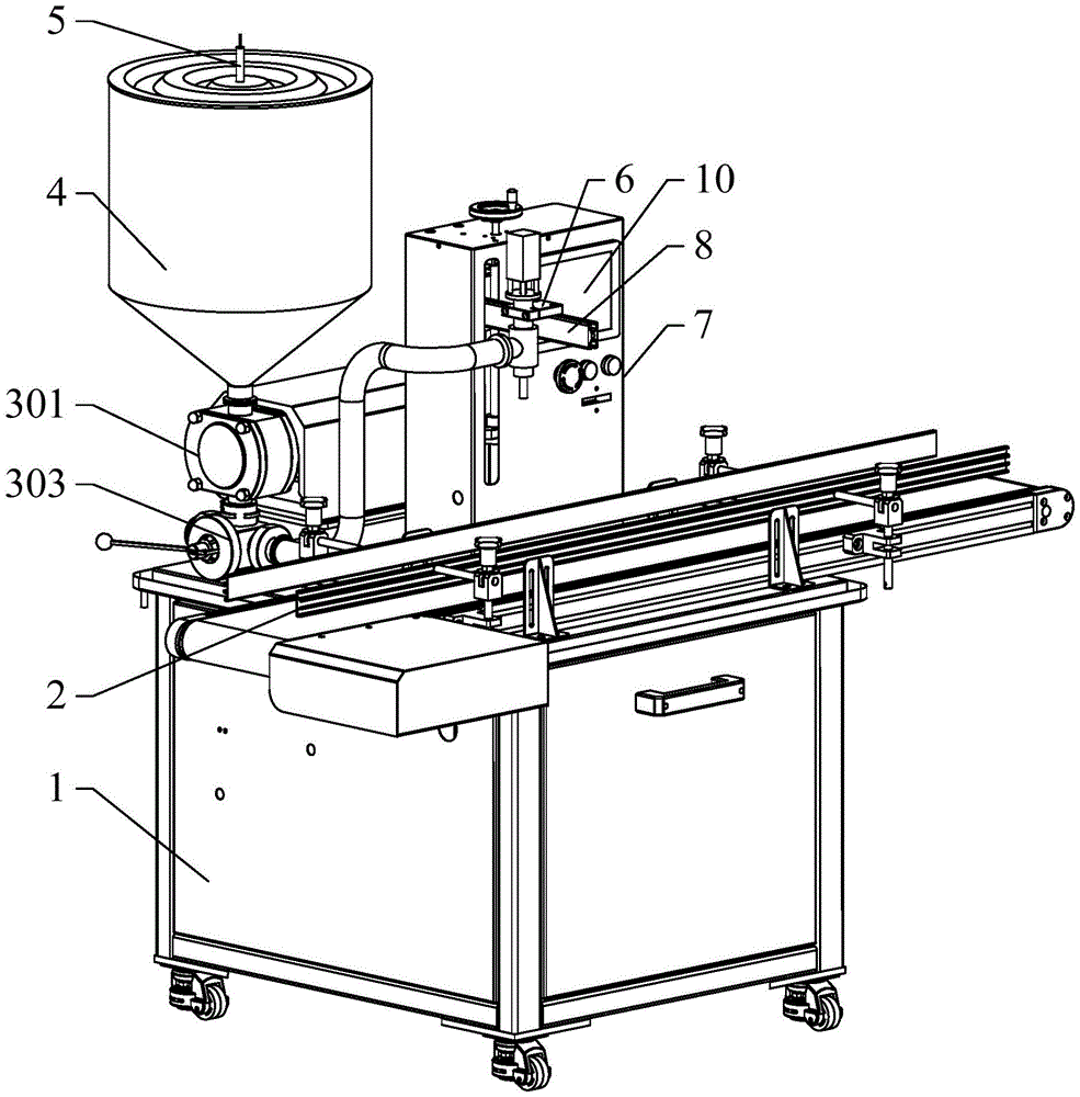
图1是本实用新型一种高精度全自动灌装机实施例的示意图;Fig. 1 is the schematic diagram of the embodiment of a kind of high-precision automatic filling machine of the present utility model;
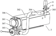
图2是本实用新型一种高精度全自动灌装机灌装机构的示意图;Fig. 2 is a schematic diagram of a filling mechanism of a high-precision automatic filling machine of the present invention;
图3是本实用新型一种高精度全自动灌装机升降装置的示意图。Fig. 3 is a schematic diagram of a lifting device of a high-precision automatic filling machine of the present invention.
附图标记:Reference signs:
1、支撑台;2、输送机构;3、灌装机构;301、转子泵;302、减速电机;303、三通球阀;304、连接管;305、灌装阀;306、进料口;307、出料口;4、储料罐;5、超声波液位监测装置;6、固定块;7、箱体;8、升降装置;801、支撑板;802、滑轨;803、滑块;804、滑台;805、连接座;806、固定底板;807、调节丝杠;808、支撑杆;809、丝杠螺母;810、丝杠支撑座;811、调节手轮;9、伸缩气缸;10、面板。1. Support platform; 2. Conveying mechanism; 3. Filling mechanism; 301. Rotor pump; 302. Geared motor; 303. Three-way ball valve; 304. Connecting pipe; 305. Filling valve; 306. Feed port; 307 , discharge port; 4, storage tank; 5, ultrasonic liquid level monitoring device; 6, fixed block; 7, box; 8, lifting device; 801, support plate; 802, slide rail; 803, slider; , sliding table; 805, connecting seat; 806, fixed base plate; 807, adjusting screw; 808, support rod; 809, screw nut; 810, screw support seat; 811, adjusting handwheel; 9, telescopic cylinder; 10 ,panel.
具体实施方式Detailed ways
以下通过附图和实施例对本实用新型的技术方案作进一步说明。The technical solution of the utility model is further described below by means of the accompanying drawings and embodiments.
除非另外定义,本实用新型使用的技术术语或者科学术语应当为本实用新型所属领域内具有一般技能的人士所理解的通常意义。本实用新型中使用的“第一”、“第二”以及类似的词语并不表示任何顺序、数量或者重要性,而只是用来区分不同的组成部分。“包括”或者“包含”等类似的词语意指出现该词前面的元件或者物件涵盖出现在该词后面列举的元件或者物件及其等同,而不排除其他元件或者物件。“连接”或者“相连”等类似的词语并非限定于物理的或者机械的连接,而是可以包括电性的连接,不管是直接的还是间接的。“上”、“下”、“左”、“右”等仅用于表示相对位置关系,当被描述对象的绝对位置改变后,则该相对位置关系也可能相应地改变。Unless otherwise defined, the technical terms or scientific terms used in the present invention shall have the usual meanings understood by those skilled in the art to which the present invention belongs. "First", "second" and similar words used in the present invention do not indicate any order, quantity or importance, but are only used to distinguish different components. "Comprising" or "comprising" and similar words mean that the elements or items appearing before the word include the elements or items listed after the word and their equivalents, without excluding other elements or items. Words such as "connected" or "connected" are not limited to physical or mechanical connections, but may include electrical connections, whether direct or indirect. "Up", "Down", "Left", "Right" and so on are only used to indicate the relative positional relationship. When the absolute position of the described object changes, the relative positional relationship may also change accordingly.
实施例Example
请参阅图1至图3,如图所示,本实用新型提供了一种高精度全自动灌装机,包括支撑台1、输送机构2、灌装机构3、储料罐4和升降机构,输送机构2设置在支撑台1的上方前侧,灌装机构3设置在输送机构2的后侧,储料罐4设置在灌装机构3的上方,储料罐4内设置有超声波液位监测装置5,用于监测储料罐4内的液位,通过监测到的液位的高低调整灌装量,升降机构设置在灌装机构3与输送机构2之间。Please refer to Figure 1 to Figure 3, as shown in the figure, the utility model provides a high-precision automatic filling machine, including a
灌装机构3包括转子泵301、减速电机302、三通球阀303、连接管304和灌装阀305,转子泵301的一端与减速电机302连接,转子泵301远离减速电机302的一端设置有进料口306和出料口307,进料口306与储料罐4的下料口连接,出料口307的下方设置有三通球阀303,三通球阀303通过连接管304与灌装阀305连接。灌装时,通过启动减速电机302带动转子泵301转动,将储料罐4中的原料通过转子泵301向下输送,同时打开三通球阀303和灌装阀305,使原料通过连接管304进入到包装瓶内。The filling mechanism 3 includes a
灌装阀305通过固定块6与升降机构连接,升降机构包括箱体7和升降装置8,升降装置8设置在箱体7的内侧。升降装置8包括支撑板801、滑轨802、滑块803、滑台804、连接座805、固定底板806和调节丝杠807,支撑板801设置在箱体7内后侧,支撑板801的前侧设置有滑轨802,滑轨802上滑动连接有滑块803,滑块803的前侧与滑台804固定连接,滑台804远离滑块803的一侧设置有支撑杆808,支撑杆808延伸至箱体7的外侧与固定块6连接。固定块6的上侧设置有伸缩气缸9,伸缩气缸9的伸缩杆贯穿固定块6与灌装阀305连接,伸缩气缸9能够带动灌装阀305进行升降运动,实现在灌装时将灌装阀305向下移动,灌装完成后将灌装阀305向上移动。Filling
滑台804的下侧通过连接座805与固定底板806连接,固定底板806的中部设置有丝杠螺母809,调节丝杠807与丝杠螺母809通过螺纹连接。调节丝杠807底端通过丝杠支撑座810与箱体7的底部连接,调节丝杠807的顶端贯穿箱体7与调节手轮811连接。通过转动调节手轮811带动调节丝杠807转动,调节丝杠807转动便带动固定底板806上下移动,固定底板806带动连接座805、滑台804、支撑杆808、固定块6依次上下移动,从而实现对灌装阀305的高度进行调节。在滑台804上下移动的同时与滑台804连接的滑块803便在滑轨802上做同步运动,从而提高滑台804上下移动的平稳性,同时也为支撑杆808提供了支撑力。The lower side of the slide table 804 is connected with the
箱体7的一侧壁上设置有面板10,面板10的背侧设置有PLC控制器,超声波液位监测装置5、减速电机302、三通球阀303、灌装阀305、伸缩气缸9均与PLC控制器电性连接。通过PLC控制器可以设定减速电机302的转速和时间,控制灌装量,设定灌装阀305的流量,控制灌装的速度。灌装阀305在灌装时先低速再高速最后再低速灌装,避免了乳液在灌装时发生溅射现象,避免造成浪费,提高灌装速度。A
灌装量是通过控制减速电机302的转动时间,从而控制转子泵301的转动圈数,转子泵301每转动一圈的下料量一定,通过调节其转动圈数便能够实现精准的灌装量,但在灌装乳液时储料罐4中的液面的高度会不断的下降,导致乳液排出的压强下降,流速变慢,但其灌装的时间不变便会导致后期的灌装量减少,对加工精度造成影响。因此本实用新型中通过使用超声波液位监测装置5监测液面的高度,然后根据液面的高度变化来改变减速电机302的转动时间,来进行补偿,从而保证灌装的精度,而减速电机302的转动时间反应到PLC控制器上的参数为灌装量,因此,可通过设置灌装量来设定减速电机302的转动时间。The filling volume is controlled by controlling the rotation time of the
而灌装量的补偿量的计算,在高液位和低液位各取一个灌装量数值,将灌装量差值和液位差值做运算,获得每mm液位补偿量,例如:高液位为1000mm,低液位为500mm时,液位差为500mm,液位重量差是10g,计算得每mm补偿量为0.02g,因此,设定为满液位时高位灌装量减(500*0.02)g,液位为800mm时灌装量减(300*0.02)g,液位为600时是灌装量减(100*0.02)g,随着实时液位降低,补偿量逐渐减小,最后趋近于零,也就是低液位的灌装量,通过设定的灌装量不同,从而使减速电机302转动的时间不同,保证每个液位下的实际灌装量相等,实现精准灌装。For the calculation of the compensation amount of the filling volume, one filling volume value is taken at the high liquid level and the low liquid level respectively, and the filling volume difference and the liquid level difference are calculated to obtain the liquid level compensation per mm, for example: When the high liquid level is 1000mm and the low liquid level is 500mm, the liquid level difference is 500mm, the liquid level weight difference is 10g, and the calculated compensation amount per mm is 0.02g. (500*0.02)g, when the liquid level is 800mm, the filling amount is reduced by (300*0.02)g, when the liquid level is 600, the filling amount is reduced by (100*0.02)g, as the real-time liquid level decreases, the compensation amount gradually Decrease, and finally approach zero, that is, the filling volume of the low liquid level. The filling volume set is different, so that the rotation time of the
具体的工作过程,将原料输送至储料罐内,通过超声波液位监测装置监测储料罐的最高液位,并将数据传输给PLC控制器,然后PLC控制器根据其液位高度控制减速电机、三通球阀和灌装阀的开启时间,输送机构将包装瓶输送至灌装阀的下侧后,伸缩气缸带动灌装阀向下移动至瓶口处,减速电机带动转子泵转动,使储料罐中的原料通过转子泵、三通球阀、连接管和灌装阀后进入到包装瓶内,完成灌装后,PLC控制器将减速电机、三通球阀和灌装阀关闭,伸缩气缸带动灌装阀向上移动,输送机构带动灌装完的包装瓶继续移动,完成出料。The specific working process is to transport the raw materials into the storage tank, monitor the maximum liquid level of the storage tank through the ultrasonic liquid level monitoring device, and transmit the data to the PLC controller, and then the PLC controller controls the geared motor according to its liquid level height , the opening time of the three-way ball valve and the filling valve, after the conveying mechanism transports the packaging bottle to the lower side of the filling valve, the telescopic cylinder drives the filling valve to move down to the bottle mouth, and the deceleration motor drives the rotor pump to rotate, so that the storage The raw materials in the material tank enter the packaging bottle through the rotor pump, three-way ball valve, connecting pipe and filling valve. After filling, the PLC controller closes the geared motor, three-way ball valve and filling valve, and the telescopic cylinder drives The filling valve moves upwards, and the conveying mechanism drives the filled packaging bottles to continue moving to complete the discharge.
因此,本实用新型采用上述结构的一种高精度全自动灌装机,灌装精度高,速度快,便于使用。Therefore, the utility model adopts a high-precision automatic filling machine with the above structure, which has high filling precision, fast speed and is easy to use.
最后应说明的是:以上实施例仅用以说明本实用新型的技术方案而非对其进行限制,尽管参照较佳实施例对本实用新型进行了详细的说明,本领域的普通技术人员应当理解:其依然可以对本实用新型的技术方案进行修改或者等同替换,而这些修改或者等同替换亦不能使修改后的技术方案脱离本实用新型技术方案的精神和范围。Finally, it should be noted that: the above embodiments are only used to illustrate the technical solutions of the present utility model and are not intended to limit it. Although the utility model has been described in detail with reference to the preferred embodiments, those of ordinary skill in the art should understand that: It is still possible to make modifications or equivalent replacements to the technical solutions of the present utility model, and these modifications or equivalent replacements cannot make the modified technical solutions deviate from the spirit and scope of the technical solutions of the present utility model.
Claims (4)
Priority Applications (1)
| Application Number | Priority Date | Filing Date | Title |
|---|---|---|---|
| CN202222427061.9U CN217895117U (en) | 2022-09-14 | 2022-09-14 | High-precision full-automatic filling machine |
Applications Claiming Priority (1)
| Application Number | Priority Date | Filing Date | Title |
|---|---|---|---|
| CN202222427061.9U CN217895117U (en) | 2022-09-14 | 2022-09-14 | High-precision full-automatic filling machine |
Publications (1)
| Publication Number | Publication Date |
|---|---|
| CN217895117U true CN217895117U (en) | 2022-11-25 |
Family
ID=84109454
Family Applications (1)
| Application Number | Title | Priority Date | Filing Date |
|---|---|---|---|
| CN202222427061.9U Active CN217895117U (en) | 2022-09-14 | 2022-09-14 | High-precision full-automatic filling machine |
Country Status (1)
| Country | Link |
|---|---|
| CN (1) | CN217895117U (en) |
-
2022
- 2022-09-14 CN CN202222427061.9U patent/CN217895117U/en active Active
Similar Documents
| Publication | Publication Date | Title |
|---|---|---|
| CN210710680U (en) | A liquid filling equipment for chemical production | |
| CN217972566U (en) | Full-automatic sauce material liquid filling machine | |
| CN113023652A (en) | Shower gel processing system | |
| CN215794615U (en) | Horizontal automatic filling machine | |
| CN110606356B (en) | A double-layer conveyor that is convenient for conveying materials | |
| CN219991130U (en) | Oral liquid filling machine | |
| CN205556613U (en) | Full -automatic dress rice steamer machine | |
| CN217918705U (en) | Automatic case sealer | |
| CN217230203U (en) | Milk is milk liquid filling machine for production and processing of milk beverage | |
| CN205701062U (en) | A kind of cup type chemicals feeder | |
| CN210942361U (en) | Liquid filling machine | |
| CN221091456U (en) | Novel automatic filling equipment | |
| CN221479499U (en) | Filling machine with adjustable filling head position | |
| CN218320753U (en) | Large capacity automatic filling machine | |
| CN220595413U (en) | Filling machine with locate function | |
| CN211139737U (en) | A feeding device for a filling machine | |
| CN219031731U (en) | Filling equipment is used in fluid sauce production | |
| CN221343975U (en) | Liquid level control structure of automatic filling machine | |
| CN221795007U (en) | Quantitative paste filling device | |
| CN220976552U (en) | Automatic split charging device for edible blend oil | |
| CN220907103U (en) | Oral liquid filling device with disinfection structure | |
| CN217172071U (en) | High-precision screw feeder | |
| CN224221778U (en) | Online vacuum defoamation biliquid encapsulating machine | |
| CN221024507U (en) | Portable honey product filling equipment | |
| CN222846078U (en) | A fixed lifting feeder |
Legal Events
| Date | Code | Title | Description |
|---|---|---|---|
| GR01 | Patent grant | ||
| GR01 | Patent grant | ||
| CP03 | Change of name, title or address |
Address after: 062150, 50 meters west of the intersection of No.1 Road North and Ruilin Road in Botou Economic Development Zone, Cangzhou City, Hebei Province Patentee after: Hebei Guangteng Machinery Equipment Co.,Ltd. Address before: 062150 No.3 Road, Botou Economic Development Zone, Cangzhou, Hebei Patentee before: BOTOU CITY GUANG TENG MACHINERY MANUFACTURING Co.,Ltd. |
|
| CP03 | Change of name, title or address |