CN217875060U - Adjustable display screen base - Google Patents
Adjustable display screen base Download PDFInfo
- Publication number
- CN217875060U CN217875060U CN202222378179.7U CN202222378179U CN217875060U CN 217875060 U CN217875060 U CN 217875060U CN 202222378179 U CN202222378179 U CN 202222378179U CN 217875060 U CN217875060 U CN 217875060U
- Authority
- CN
- China
- Prior art keywords
- display screen
- plate
- fixedly mounted
- down motion
- install bin
- Prior art date
- Legal status (The legal status is an assumption and is not a legal conclusion. Google has not performed a legal analysis and makes no representation as to the accuracy of the status listed.)
- Expired - Fee Related
Links
- 230000033001 locomotion Effects 0.000 claims abstract description 48
- 238000009434 installation Methods 0.000 claims description 20
- 230000037431 insertion Effects 0.000 claims 3
- 238000003780 insertion Methods 0.000 claims 3
- 230000001360 synchronised effect Effects 0.000 abstract description 7
- 239000000203 mixture Substances 0.000 abstract description 3
- 238000000034 method Methods 0.000 description 4
- 230000000694 effects Effects 0.000 description 3
- 230000001105 regulatory effect Effects 0.000 description 2
- 230000005540 biological transmission Effects 0.000 description 1
- 230000006386 memory function Effects 0.000 description 1
- 239000011435 rock Substances 0.000 description 1
Images



Landscapes
- Devices For Indicating Variable Information By Combining Individual Elements (AREA)
Abstract
The utility model discloses a display screen base with adjustable belongs to computer technology field, comprising a base plate, the last fixed surface of bottom plate installs the support frame, the side of support frame is provided with the install bin, be provided with the up-and-down motion subassembly that is used for ordering about the install bin up-and-down motion in the support frame, it installs two pivots to rotate on the install bin, the equal fixed mounting in top of two pivots has the leading truck, be provided with the adjusting part that is used for adjusting two pivot turned angle in the install bin, the top of install bin is provided with three bracing piece, one of them bracing piece fixed mounting is on the install bin, two other bracing pieces are sliding mounting respectively in the leading truck and tip fixed mounting have a limiting plate, through setting up the up-and-down motion subassembly, utilize the up-and-down motion subassembly to drive the install bin up-and-down motion, the install bin up-and-down motion can drive the synchronous up-and-down motion of display screen through the leading truck, realize the altitude mixture control to the display screen, and the application range is improved.
Description
Technical Field
The utility model relates to a computer technology field especially relates to a display screen base with adjustable.
Background
The computer is commonly called as computer, is a modern electronic computing machine for high-speed computation, can perform numerical computation and logic computation, and also has a memory function, and meanwhile, a computer display screen is an important part of the computer, and is a display tool for displaying certain electronic file information on the screen through specific transmission equipment and reflecting the electronic file information to human eyes.
The existing computer display screen is mostly fixed, can not carry out the regulation on some angles or height to the display screen, uses comparatively to limit, and along with social development, some staff have begun to use the condition that a plurality of display screens worked an official business, need use a plurality of supports to fix the display screen, and it is comparatively troublesome to use.
SUMMERY OF THE UTILITY MODEL
The utility model provides a display screen base with adjustable has solved that current computer display screen is mostly fixed, can not carry out the regulation on some angles or height to the display screen, uses comparatively to limit to, and along with social development, some staff have begun to use the condition that a plurality of display screens worked an official business, need use a plurality of supports to fix the display screen, use comparatively trouble problem.
In order to achieve the above purpose, the utility model adopts the following technical scheme: the utility model provides a display screen base with adjustable, includes the bottom plate, the last fixed surface of bottom plate installs the support frame, the side of support frame is provided with the install bin, be provided with the up-and-down motion subassembly that is used for ordering about the install bin up-and-down motion in the support frame, rotate on the install bin and install two pivots, two the equal fixed mounting in top of pivot has the leading truck, be provided with the adjusting part who is used for adjusting two pivot turned angle in the install bin, the top of install bin is provided with three bracing piece, one of them bracing piece fixed mounting is on the install bin, and two in addition the bracing piece is respectively slidable mounting in the leading truck and end fixing has a limiting plate, and is three the side of bracing piece all is provided with the display screen mounting panel, a plurality of mounting hole has been seted up on the display screen mounting panel, the side fixed mounting of display screen mounting panel has the fixed plate, the surface of bracing piece rotates installs the disc, be connected through elastic component between fixed plate and the disc, the opposite face that fixed plate and the disc are relative one side equal fixed mounting has the spacing ring and two spacing rings all have the tooth that mutually support the mutually supporting use.
Adopt above-mentioned scheme, through setting up the bracing piece, the disc, the spacing ring, the fixed plate, display screen mounting panel and elastic component, pulling display screen mounting panel makes the display screen mounting panel drive the fixed plate motion, the fixed plate motion orders about two spacing boards and keeps away from mutually, in order to relieve the spacing fixed to the fixed plate, thereby can adjust the turned angle of display screen mounting panel and display screen, loosen the display screen mounting panel, make the fixed plate drive the display screen mounting panel under elastic component's elasticity and be close to the disc, thereby make two spacing rings mesh mutually, and then realize the regulation to display screen turned angle, can use other modes such as perpendicular screen and horizontal screen to the display screen according to the user demand, improve the variety that the display screen used, through setting up the up-and-down motion subassembly, utilize the up-down motion subassembly to drive the installation box up-and-down motion, the installation box up-and-down motion can drive the synchronous up-and-down motion of display screen through the leading truck, in order to realize the altitude mixture control to the display screen, through setting up the regulating component, the turned angle that can adjust two pivots can be adjusted to utilize the regulating component, the display screen both sides can be driven in the display screen both sides when the pivot pivoted, be convenient for adjusting the expansion angle according to the user demand, further improve the application range.
As a preferred scheme of the utility model, the up-and-down motion subassembly is installed including rotating the tip of installing threaded rod and the threaded rod in the support frame and is changeed board one, the side fixed mounting of install bin has the slider, the slider screw thread is installed and is laminated mutually at the surface of threaded rod and the inner wall of slider and support frame.
Adopt above-mentioned scheme, through setting up threaded rod and slider, utilize the slider to play the effect of spacing direction to the install bin, utilize commentaries on classics board one to drive the threaded rod and rotate, threaded rod normal running fit slider drives the install bin up-and-down motion, the install bin up-and-down motion can drive the leading truck up-and-down motion through the pivot to can drive the synchronous up-and-down motion of display screen, with the realization to the regulation of display screen high position, be convenient for adjust the height of display screen according to the user demand, thereby improve application scope.
As a preferred scheme of the utility model, adjusting part includes the worm wheel of fixed mounting pivot bottom, two worms, one of them are installed to the install bin internal rotation commentaries on classics board two, two are installed to the tip of worm the screw opposite direction of worm just fixed connection between two worms, two the worm wheel meshes with two worms respectively mutually.
Adopt above-mentioned scheme, through setting up worm wheel and worm, rotate two messenger of commentaries on classics board and change two drive worms of board and rotate, the worm rotates and drives the pivot through the worm wheel and rotate, and then realizes the angle modulation work to the pivot, and the pivot is rotated and can be driven the leading truck and rotate to can drive the synchronous rotation of display screen of both sides, be convenient for adjust the expansion angular position of both sides display screen according to the user demand, further improve application scope.
As the utility model discloses a preferred scheme, slidable mounting has two inserted bars, two on the limiting plate the tip fixed mounting of inserted bar has same arm-tie, set up a plurality of on the leading truck and supply inserted bar male slot.
Adopt above-mentioned scheme, through setting up arm-tie and inserted bar, drive the inserted bar motion through the arm-tie, make the inserted bar break away from the slot to it is fixed to relieve the locking of limiting plate, press down the arm-tie and make the arm-tie drive the inserted bar motion, make the inserted bar insert the spacing inslot, fixed in order to realize the locking to the limiting plate, avoid the condition that the limiting plate takes place the motion in the use, easy operation, convenient to use.
As the utility model discloses an optimal scheme, the surface cover of inserted bar is equipped with spring one, the both ends of spring one fixed mounting respectively is on limiting plate and arm-tie.
Adopt above-mentioned scheme, through setting up spring one, utilize the elasticity of spring one to order about the inserted bar and get back to the normal position fast, make the inserted bar can be faster insert in the slot to better lock the limiting plate fixedly, can avoid the inserted bar to take place the condition that drops simultaneously, further improve the stability of using.
As a preferred scheme of the utility model, elastic component includes a plurality of spring two of fixed mounting in the disc side, the other end fixed mounting of spring two is on the fixed plate, be provided with the telescopic link in the spring two, the both ends difference fixed mounting of telescopic link is on disc and fixed plate.
Adopt above-mentioned scheme, through setting up spring two and telescopic link, utilize the telescopic link to play the effect that supports the direction to spring two to avoid two motion in-process of spring to take place to rock the condition of skew, utilize the elasticity of spring two to order about between disc and the fixed plate and be close to each other, make two spacing rings mesh mutually, further can realize the spacing fixed to the display screen mounting panel, avoid display screen mounting panel atress to take place the pivoted condition in the use.
The utility model discloses in:
the adjustable display screen base is provided with the supporting rods, the disc, the limiting rings, the fixed plate, the display screen mounting plate and the elastic assembly, the display screen mounting plate is pulled to drive the display screen mounting plate to move, the fixed plate moves to drive the two limiting rings to be away from each other, limiting fixation on the fixed plate is relieved, the rotating angles of the display screen mounting plate and the display screen can be adjusted, the display screen mounting plate is loosened, the fixed plate drives the display screen mounting plate to be close to the disc under the elastic force of the elastic assembly, the two limiting rings are meshed, adjustment of the rotating angle of the display screen is achieved, the display screen can be used in other modes such as a vertical screen mode and a horizontal screen mode according to use requirements, and the use diversity of the display screen is improved;
according to the adjustable display screen base, the threaded rod and the sliding block are arranged, the sliding block is used for limiting and guiding the installation box, the rotating plate I is used for driving the threaded rod to rotate, the threaded rod is matched with the sliding block in a rotating mode to drive the installation box to move up and down, the installation box can move up and down through the rotating shaft, the guide frame can be driven to move up and down through the up-and-down movement of the installation box, the display screen can be driven to move up and down synchronously, the height position of the display screen can be adjusted, the height of the display screen can be adjusted conveniently according to use requirements, and therefore the application range is improved;
this display screen base with adjustable utilize the turned angle that adjusting part can adjust two pivots, can drive the display screen motion of both sides through the leading truck when pivot pivoted, is convenient for adjust the expansion angle of both sides display screen according to the user demand, further improves application range.
Drawings
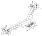
Fig. 1 is a schematic structural view of the present invention;
fig. 2 is a schematic structural view of another aspect of the present invention;
FIG. 3 is a schematic view of the supporting frame of the present invention;
fig. 4 is a schematic structural view of the guide frame of the present invention;
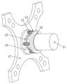
FIG. 5 is a schematic structural view of the stop collar of the present invention;
fig. 6 is an enlarged schematic view of a portion a of fig. 4 according to the present invention.
In the figure: 1. a base plate; 2. a support frame; 3. a threaded rod; 4. a slider; 5. installing a box; 6. pulling a plate; 7. inserting a rod; 8. a first spring; 9. a limiting plate; 10. a guide frame; 11. a support bar; 12. a disc; 13. a telescopic rod; 14. a second spring; 15. a limiting ring; 16. a fixing plate; 17. a display screen mounting plate; 18. a worm; 19. a rotating shaft; 20. a worm gear.
Detailed Description
Examples
Referring to fig. 1-6, the utility model provides an adjustable display screen base, including a bottom plate 1, the upper surface of bottom plate 1 is fixed and is installed support frame 2, the side of support frame 2 is provided with installation box 5, be provided with the up-and-down motion subassembly that is used for driving installation box 5 up-and-down motion in the support frame 2, the up-and-down motion subassembly includes that the threaded rod 3 that rotates and installs in support frame 2 and the tip of threaded rod 3 installs commentaries on classics board one, the side fixed mounting of installation box 5 has slider 4, slider 4 threaded mounting is at the surface of threaded rod 3 and slider 4 is laminated with the inner wall of support frame 2 mutually, through setting up threaded rod 3 and slider 4, utilize slider 4 to play the effect of spacing direction to installation box 5, utilize commentaries on classics board one to drive threaded rod 3 and rotate, threaded rod 3 normal running fit slider 4 drives installation box 5 up-and-down motion, the up-and-down motion of installation box 5 can drive leading truck 10 up-and-down motion through pivot 19, thereby can drive the synchronous up-and-down motion of display screen, so as to realize the regulation of display screen height position, be convenient for adjusting the height of display screen according to the user demand, thereby improve application scope;
the mounting box 5 is rotatably provided with two rotating shafts 19, the top ends of the two rotating shafts 19 are fixedly provided with guide frames 10, the mounting box 5 is internally provided with an adjusting assembly for adjusting the rotating angle of the two rotating shafts 19, the adjusting assembly comprises worm wheels 20 fixedly provided with the bottom ends of the rotating shafts 19, the mounting box 5 is rotatably provided with two worms 18, the end part of one worm 18 is provided with a rotating plate II, the thread directions of the two worms 18 are opposite, the two worms 18 are fixedly connected, the two worm wheels 20 are respectively meshed with the two worms 18, the rotating plate II is rotated to drive the worm 18 to rotate, the worm 18 rotates to drive the rotating shafts 19 to rotate through the worm wheels 20, so that the angle adjusting work of the rotating shafts 19 is realized, the rotating shafts 19 can drive the guide frames 10 to rotate, thereby driving the display screens on the two sides to synchronously rotate, the unfolding angle positions of the display screens on the two sides can be adjusted according to the use requirements, and the application range is further improved;
three support rods 11 are arranged above the installation box 5, one support rod 11 is fixedly arranged on the installation box 5, the other two support rods 11 are respectively arranged in a guide frame 10 in a sliding mode, a limiting plate 9 is fixedly arranged at the end part of each support rod, two inserting rods 7 are arranged on each limiting plate 9 in a sliding mode, the end parts of the two inserting rods 7 are fixedly provided with the same pull plate 6, a plurality of slots for the inserting rods 7 to insert are formed in the guide frame 10, the pull plates 6 and the inserting rods 7 are arranged, the inserting rods 7 are driven by the pull plates 6 to move, the inserting rods 7 are separated from the slots, locking and fixing of the limiting plates 9 are released, the pull plates 6 are pressed to drive the inserting rods 7 to move, the inserting rods 7 are inserted into the limiting grooves, locking and fixing of the limiting plates 9 are achieved, the situation that the limiting plates 9 move in the use process is avoided, operation is simple, and use is convenient;
the spring I8 is sleeved on the outer surface of the inserting rod 7, two ends of the spring I8 are fixedly installed on the limiting plate 9 and the pulling plate 6 respectively, and through the arrangement of the spring I8, the elasticity of the spring I8 is utilized to drive the inserting rod 7 to quickly return to the original position, so that the inserting rod 7 can be inserted into the slot more quickly, the limiting plate 9 can be locked and fixed better, meanwhile, the condition that the inserting rod 7 falls off can be avoided, and the use stability is further improved;
the side surfaces of the three support rods 11 are respectively provided with a display screen mounting plate 17, the display screen mounting plate 17 is provided with a plurality of mounting holes, the side surface of the display screen mounting plate 17 is fixedly provided with a fixing plate 16, the outer surface of each support rod 11 is rotatably provided with a disc 12, the fixing plate 16 is connected with the disc 12 through an elastic assembly, the elastic assembly comprises a plurality of second springs 14 fixedly arranged on the side surface of the disc 12, the other ends of the second springs 14 are fixedly arranged on the fixing plate 16, telescopic rods 13 are arranged in the second springs 14, two ends of each telescopic rod 13 are respectively fixedly arranged on the disc 12 and the fixing plate 16, the second springs 14 and the telescopic rods 13 are arranged, the telescopic rods 13 are used for supporting and guiding the second springs 14 so as to avoid the situation that the second springs 14 shake and offset occur in the movement process, the elastic discs 12 of the second springs 14 and the fixing plates 16 are close to each other so that the two limit rings 15 are meshed with each other, further limiting and fixing of the display screen mounting plate 17 can be realized, and the situation that the display screen mounting plate 17 is prevented from rotating under the applied force in the use process;
the fixing plate 16 and the disc 12 are fixedly provided with a limiting ring 15 on the opposite side, the opposite sides of the two limiting rings 15 are provided with teeth which are matched with each other for use, the supporting rod 11, the disc 12, the limiting ring 15, the fixing plate 16, the display screen mounting plate 17 and the elastic component are arranged, the display screen mounting plate 17 is pulled to enable the display screen mounting plate 17 to drive the fixing plate 16 to move, the fixing plate 16 moves to drive the two limiting plates 9 to be away from each other so as to relieve the limiting fixation of the fixing plate 16, thereby the rotating angles of the display screen mounting plate 17 and the display screen can be adjusted, the display screen mounting plate 17 is loosened, the fixing plate 16 drives the display screen mounting plate 17 to be close to the disc 12 under the elasticity of the elastic component, thereby the two limiting rings 15 are meshed with each other, and then realize the regulation to display screen turned angle, can erect other modes such as screen and horizontal screen to the display screen according to the user demand and use, improve the variety that the display screen used, through setting up the up-and-down motion subassembly, utilize the up-and-down motion subassembly to drive the 5 up-and-down motion of install bin, the up-and-down motion of install bin 5 can drive the synchronous up-and-down motion of display screen through leading truck 10, with the realization to the altitude mixture control of display screen, through setting up adjusting part, utilize adjusting part can adjust two pivot 19's turned angle, can drive the display screen motion of both sides through leading truck 10 when pivot 19 pivoted, be convenient for adjust the expansion angle of both sides display screen according to the user demand, further improve application range.
The working principle is as follows: when the display screen adjusting device is used, firstly, a display screen is installed on a display screen installing plate 17 through bolts, then, the pulling plate 6 is pulled, the pulling plate 6 drives the inserting rod 7 to move, the inserting rod 7 is separated from the slot, the locking and fixing of the limiting plate 9 are released, then, the display screen is adjusted to a proper position, the pulling plate 6 is loosened, the inserting rod 7 is inserted into the slot under the action of the elastic force of the first spring 8, the locking and fixing of the limiting plate 9 are realized, then, the second rotating plate is rotated, the second rotating plate drives the worm 18 to rotate, the worm 18 rotates to drive the rotating shaft 19 to rotate through the worm wheel 20, further, the angle adjusting work of the rotating shaft 19 is realized, the rotating shaft 19 can drive the guide frame 10 to rotate for adjusting the unfolding angle of the display screens on two sides, then, the first rotating plate is rotated, the threaded rod 3 is driven to rotate by the first rotating plate, the threaded rod 3 is in running fit with the sliding block 4 to drive the installing box 5 to move up and down, the up-and-down motion of installing box 5 can drive leading truck 10 up-and-down motion through pivot 19, thereby can drive the synchronous up-and-down motion of display screen, in order to realize the regulation to the display screen high position, when needing to adjust display screen self angle, pulling display screen mounting panel 17 makes display screen mounting panel 17 drive fixed plate 16 motion, fixed plate 16 motion orders about two limiting plates 9 and keeps away from mutually, in order to relieve the spacing fixed to fixed plate 16, thereby can display screen self turned angle, after the display screen angle is confirmed, loosen display screen mounting panel 17, make fixed plate 16 drive display screen mounting panel 17 under the elasticity of spring two 14 and be close to disc 12, thereby make two spacing rings 15 mesh mutually, carry out spacing fixed to fixed plate 16 and display screen mounting panel 17, can.
Claims (6)
1. The adjustable display screen base is characterized by comprising a bottom plate (1), a support frame (2) is fixedly mounted on the upper surface of the bottom plate (1), an installation box (5) is arranged on the side surface of the support frame (2), an up-and-down movement assembly used for driving the installation box (5) to move up and down is arranged in the support frame (2), two rotating shafts (19) are rotatably mounted on the installation box (5), a guide frame (10) is fixedly mounted at the top ends of the two rotating shafts (19), an adjusting assembly used for adjusting the rotating angles of the two rotating shafts (19) is arranged in the installation box (5), three support rods (11) are arranged above the installation box (5), one support rod (11) is fixedly mounted on the installation box (5), the other two support rods (11) are respectively slidably mounted in the guide frame (10), a limiting plate (9) is fixedly mounted at the end part of each support rod, display screen mounting plates (17) are arranged on the side surfaces of the three support rods (11), a plurality of mounting holes are formed in the display screen mounting plates (17), a fixing plate (16) is fixedly mounted on the side surfaces of the display screen mounting plates (17), a fixing plate (16), a fixing plate (12) is mounted on the outer surface of the support rods (11), and the disc (12) is connected with an elastic fixing plate assembly (12), the opposite surfaces of the fixing plate (16) and the disc (12) are fixedly provided with limit rings (15) and the opposite surfaces of the two limit rings (15) are provided with teeth which are matched with each other for use.
2. The adjustable display screen base as claimed in claim 1, wherein the up-and-down movement assembly comprises a threaded rod (3) rotatably mounted in the support frame (2), a first rotating plate is mounted at the end of the threaded rod (3), a sliding block (4) is fixedly mounted on the side surface of the mounting box (5), the sliding block (4) is mounted on the outer surface of the threaded rod (3) in a threaded manner, and the sliding block (4) is attached to the inner wall of the support frame (2).
3. The adjustable display screen base as claimed in claim 1, wherein the adjusting assembly comprises a worm wheel (20) fixedly mounted at the bottom end of a rotating shaft (19), two worms (18) are rotatably mounted in the mounting box (5), a second rotating plate is mounted at the end of one worm (18), the two worms (18) have opposite thread directions and are fixedly connected with each other, and the two worm wheels (20) are respectively meshed with the two worms (18).
4. The adjustable display screen base according to claim 1, wherein two insertion rods (7) are slidably mounted on the limiting plate (9), the end portions of the two insertion rods (7) are fixedly mounted with a same pulling plate (6), and a plurality of slots for the insertion rods (7) to be inserted are formed in the guide frame (10).
5. The adjustable display screen base as claimed in claim 4, wherein the outer surface of the inserted rod (7) is sleeved with a first spring (8), and two ends of the first spring (8) are respectively and fixedly mounted on the limiting plate (9) and the pulling plate (6).
6. The adjustable display screen base according to claim 1, wherein the elastic assembly comprises a plurality of second springs (14) fixedly mounted on the side surface of the disc (12), the other ends of the second springs (14) are fixedly mounted on the fixing plate (16), telescopic rods (13) are arranged in the second springs (14), and the two ends of the telescopic rods (13) are fixedly mounted on the disc (12) and the fixing plate (16) respectively.
Priority Applications (1)
| Application Number | Priority Date | Filing Date | Title |
|---|---|---|---|
| CN202222378179.7U CN217875060U (en) | 2022-09-07 | 2022-09-07 | Adjustable display screen base |
Applications Claiming Priority (1)
| Application Number | Priority Date | Filing Date | Title |
|---|---|---|---|
| CN202222378179.7U CN217875060U (en) | 2022-09-07 | 2022-09-07 | Adjustable display screen base |
Publications (1)
| Publication Number | Publication Date |
|---|---|
| CN217875060U true CN217875060U (en) | 2022-11-22 |
Family
ID=84080704
Family Applications (1)
| Application Number | Title | Priority Date | Filing Date |
|---|---|---|---|
| CN202222378179.7U Expired - Fee Related CN217875060U (en) | 2022-09-07 | 2022-09-07 | Adjustable display screen base |
Country Status (1)
| Country | Link |
|---|---|
| CN (1) | CN217875060U (en) |
Cited By (2)
| Publication number | Priority date | Publication date | Assignee | Title |
|---|---|---|---|---|
| CN116006845A (en) * | 2022-12-16 | 2023-04-25 | 徐州长航科技有限公司 | Crane display capable of adjusting height and rotation angle |
| CN118462963A (en) * | 2023-05-05 | 2024-08-09 | 赵婷婷 | Computer display device with regulatory function |
-
2022
- 2022-09-07 CN CN202222378179.7U patent/CN217875060U/en not_active Expired - Fee Related
Cited By (2)
| Publication number | Priority date | Publication date | Assignee | Title |
|---|---|---|---|---|
| CN116006845A (en) * | 2022-12-16 | 2023-04-25 | 徐州长航科技有限公司 | Crane display capable of adjusting height and rotation angle |
| CN118462963A (en) * | 2023-05-05 | 2024-08-09 | 赵婷婷 | Computer display device with regulatory function |
Similar Documents
| Publication | Publication Date | Title |
|---|---|---|
| CN112097020A (en) | LED display screen that can go up and down | |
| CN211902134U (en) | Computer display screen base device | |
| CN114607887A (en) | Multifunctional multimedia teaching device | |
| CN210120519U (en) | But angle regulation's photovoltaic board mounting bracket | |
| CN111810796A (en) | A three-axis adjustable mobile computer frame device | |
| CN219263650U (en) | Support frame for two-way installation LED screen | |
| CN218069241U (en) | LED display screen capable of being adjusted through horizontal displacement | |
| CN219013740U (en) | Display screen convenient to angle regulation | |
| CN111637340A (en) | Adjustable computer display screen | |
| CN222142511U (en) | Enterprise management multi-regulation projection equipment | |
| CN212805159U (en) | LED display screen fixing frame | |
| CN210324965U (en) | Folding highlight display screen | |
| CN203882240U (en) | Hanging screen integrated computer | |
| CN222068017U (en) | Liquid crystal display based on IC dynamic driving display signal | |
| CN223709132U (en) | Rotary anti-shaking computer display screen | |
| CN221383113U (en) | Picture frame with adjustable mounting position | |
| CN220604180U (en) | Electronic platform multifunctional teaching touch control integrated machine | |
| CN217037102U (en) | A semi-hanging photovoltaic bracket | |
| CN212408096U (en) | Integrated spliced liquid crystal display screen | |
| CN222011503U (en) | Control system device with high regulation | |
| CN221258162U (en) | Intelligent integrated machine | |
| CN212537230U (en) | A mounting bracket for human projecting apparatus | |
| CN219680134U (en) | Information recording plate capable of adjusting angle | |
| CN223825971U (en) | School monitoring probe support | |
| CN213692734U (en) | Electric control cabinet convenient to dismantle |
Legal Events
| Date | Code | Title | Description |
|---|---|---|---|
| GR01 | Patent grant | ||
| GR01 | Patent grant | ||
| CF01 | Termination of patent right due to non-payment of annual fee |
Granted publication date: 20221122 |
|
| CF01 | Termination of patent right due to non-payment of annual fee |