CN217834534U - Single-cavity double-injection mold structure for automobile plastic part - Google Patents
Single-cavity double-injection mold structure for automobile plastic part Download PDFInfo
- Publication number
- CN217834534U CN217834534U CN202221460390.7U CN202221460390U CN217834534U CN 217834534 U CN217834534 U CN 217834534U CN 202221460390 U CN202221460390 U CN 202221460390U CN 217834534 U CN217834534 U CN 217834534U
- Authority
- CN
- China
- Prior art keywords
- fixed
- mold
- cavity
- movable
- column
- Prior art date
- Legal status (The legal status is an assumption and is not a legal conclusion. Google has not performed a legal analysis and makes no representation as to the accuracy of the status listed.)
- Active
Links
Images



Landscapes
- Moulds For Moulding Plastics Or The Like (AREA)
Abstract
本实用新型涉及汽车塑胶件制造技术领域,特别是涉及一种汽车塑胶件单腔双射模具结构,包括工作台,工作台上端部对称开设有燕尾槽,工作台下端部固定安装有底板,工作台上端部固定安装有定模,定模侧壁上开设有第一模腔,定模前端设置有固定框架,固定框架内部对称设置有螺旋给料筒,脱模机构包括动模,动模与工作台和定模均活动连接,动模下端部对称固定安装有燕尾块,两个燕尾块分别滑动安装在两个燕尾槽中,动模与定模相对的一端上开设有第二模腔,第二模腔内壁中部开设有第一顶出槽,第一顶出槽内壁中部开设有第一柱槽,在两次顶出力的作用下完成脱模,其有效增大了脱模时的顶出面积,使得脱模不易发生粘连且便捷度更高。

The utility model relates to the technical field of automobile plastic parts manufacturing, in particular to a single-cavity double-shot mold structure for automobile plastic parts. A fixed mold is fixedly installed on the end of the table, and the first cavity is opened on the side wall of the fixed mold. The workbench and the fixed mold are both movably connected, and the lower end of the movable mold is symmetrically fixed with a dovetail block, and the two dovetail blocks are respectively slidably installed in two dovetail grooves, and a second cavity is provided on the opposite end of the movable mold and the fixed mold. The middle part of the inner wall of the second mold cavity is provided with a first ejection groove, and the middle part of the inner wall of the first ejection groove is provided with a first column groove, and the demoulding is completed under the action of two ejection forces, which effectively increases the ejection force during demoulding. Out of the area, making demoulding less prone to sticking and more convenient.
Description
技术领域technical field
本实用新型涉及汽车塑胶件制造技术领域,特别是涉及一种汽车塑胶件单腔双射模具结构。The utility model relates to the technical field of manufacturing automobile plastic parts, in particular to a single-cavity double-shot mold structure for automobile plastic parts.
背景技术Background technique
注塑成型又称注射模塑成型,它是一种注射兼模塑的成型方法,注塑成型方法的优点是生产速度快、效率高,操作可实现自动化,花色品种多,形状可以由简到繁,尺寸可以由大到小,而且制品尺寸精确,产品易更新换代,能成形状复杂的制件,注塑成型适用于大量生产与形状复杂产品等成型加工领域。Injection molding, also known as injection molding, is a molding method of injection and molding. The advantages of injection molding method are fast production speed, high efficiency, automatic operation, various designs and colors, and shapes from simple to complex. The size can range from large to small, and the product size is accurate, the product is easy to replace, and can be formed into parts with complex shapes. Injection molding is suitable for mass production and complex-shaped products and other molding processing fields.
如中国专利公开了:一种细长孔塑胶件成型模具结构,公开号:CN215849368U,本实用新型采用了能够伸缩的司筒本体,能够在注胶腔射胶时通过射胶压力推动司筒本体后退移动,使孔针在射胶的过程中逐渐变化长度,直到产品需要的程度,本实用新型由于孔针在未注胶时伸出的长度比较短,部容易被射胶压力冲断或是冲变形,能够有效的保护孔针,但该模具在实际使用时脱模易与模腔发生粘连,从而在强力脱模时容易造成塑胶件发生损坏,从而造成经济损失。For example, the Chinese patent discloses: a mold structure for forming plastic parts with slender holes, publication number: CN215849368U. The utility model adopts a retractable cylinder body, which can push the cylinder body through the injection pressure when injecting glue in the injection chamber. Move back, so that the length of the hole needle gradually changes during the injection process until the product needs it. Because the length of the hole needle is relatively short when it is not injected, the part of the utility model is easily broken by the injection pressure or Punching deformation can effectively protect the hole needle, but the mold is easy to stick to the mold cavity during demoulding in actual use, so that the plastic parts are easily damaged during strong demoulding, resulting in economic losses.
实用新型内容Utility model content
为了克服现有技术的不足,本实用新型提供一种汽车塑胶件单腔双射模具结构。In order to overcome the deficiencies of the prior art, the utility model provides a single-cavity double-shot mold structure for automobile plastic parts.
为解决上述技术问题,本实用新型提供如下技术方案:一种汽车塑胶件单腔双射模具结构,包括工作台,所述工作台上端部对称开设有燕尾槽,所述工作台下端部固定安装有底板,所述工作台上端部固定安装有定模,所述定模侧壁上开设有第一模腔,所述定模前端设置有固定框架,所述固定框架内部对称设置有螺旋给料筒,两个所述螺旋给料筒注射口均内设在定模中且与第一模腔相连通;In order to solve the above technical problems, the utility model provides the following technical solutions: a single-cavity double-shot mold structure for automobile plastic parts, including a workbench, the upper end of the workbench is symmetrically provided with dovetail grooves, and the lower end of the workbench is fixed and installed There is a bottom plate, a fixed mold is fixedly installed on the upper end of the workbench, a first mold cavity is opened on the side wall of the fixed mold, a fixed frame is arranged at the front end of the fixed mold, and a screw feeder is symmetrically arranged inside the fixed frame. barrel, and the injection ports of the two screw feeding barrels are both set in the fixed mold and communicated with the first cavity;
所述工作台上端部固定安装有上料机构;A feeding mechanism is fixedly installed on the upper end of the workbench;
所述上料机构包括支撑板,两个所述支撑板均与工作台固定连接,两个所述支撑板之间固定安装有原料箱;The feeding mechanism includes a support plate, both of the two support plates are fixedly connected to the workbench, and a raw material box is fixedly installed between the two support plates;
所述定模后端设置有脱模机构;The rear end of the fixed mold is provided with a demoulding mechanism;
所述脱模机构包括动模,所述动模与工作台和定模均活动连接,所述动模下端部对称固定安装有燕尾块,两个所述燕尾块分别滑动安装在两个燕尾槽中。The demoulding mechanism includes a movable mold, the movable mold is movably connected with the workbench and the fixed mold, the lower end of the movable mold is symmetrically fixed with a dovetail block, and the two dovetail blocks are respectively slidably installed in two dovetail grooves middle.
作为本实用新型的一种优选技术方案,所述原料箱上端部四角处均开设有插孔,四个所述插孔内部均滑动安装有插柱,四个所述插柱上端部固定安装有盖板,所述原料箱内壁中固定安装有分隔板。As a preferred technical solution of the present utility model, sockets are provided at the four corners of the upper end of the raw material box, inserting posts are slidably installed inside the four inserting holes, and the upper ends of the four inserting posts are fixedly installed with A cover plate, a partition plate is fixedly installed in the inner wall of the raw material box.
作为本实用新型的一种优选技术方案,所述动模与定模相对的一端上开设有第二模腔,所述第二模腔内壁中部开设有第一顶出槽,所述第一顶出槽内壁中部开设有第一柱槽,所述第二模腔内壁外围开设有第二顶出槽,所述第二顶出槽内壁中均匀等距开设有第二柱槽。As a preferred technical solution of the present invention, a second mold cavity is provided on the opposite end of the movable mold to the fixed mold, a first ejection groove is opened in the middle of the inner wall of the second mold cavity, and the first ejector The middle part of the inner wall of the outlet groove is provided with a first column groove, and the outer periphery of the inner wall of the second mold cavity is provided with a second ejection groove, and the inner wall of the second ejection groove is evenly and equidistantly provided with second column grooves.
作为本实用新型的一种优选技术方案,所述动模后端设置有固定块,所述固定块与工作台固定连接,所述固定块侧壁中部固定安装有中心柱,所述中心柱远离固定块的一端上固定安装有第一顶盘,所述第一顶盘和中心柱分别活动内设在第一顶出槽和第一柱槽中。As a preferred technical solution of the present utility model, a fixed block is provided at the rear end of the movable mold, and the fixed block is fixedly connected with the workbench. A first top plate is fixedly installed on one end of the fixed block, and the first top plate and the center column are movably arranged in the first ejection groove and the first column groove respectively.
作为本实用新型的一种优选技术方案,所述固定块内部滑动安装有活动柱,四个所述活动柱表面均活动套设有弹簧,四个所述活动柱表面上均固定套设有固定环,四个所述活动柱两端分别与固定块和固定环固定连接。As a preferred technical solution of the present invention, movable columns are slidably installed inside the fixed block, springs are movably sleeved on the surfaces of the four movable columns, and fixed springs are fixedly sleeved on the surfaces of the four movable columns. ring, and the two ends of the four movable columns are respectively fixedly connected with the fixed block and the fixed ring.
作为本实用新型的一种优选技术方案,所述活动柱远离固定块的一端固定安装有第二顶盘,所述活动柱和第二顶盘分别滑动内设在第二柱槽和第二顶出槽中。As a preferred technical solution of the present utility model, the end of the movable column far away from the fixed block is fixedly installed with a second top plate, and the movable column and the second top plate are slidingly arranged in the second column groove and the second top plate respectively. Out of slot.
与现有技术相比,本实用新型能达到的有益效果是:Compared with the prior art, the beneficial effects that the utility model can achieve are:
其一,在活动柱的滑动下将带动与之固定的固定环发生滑动,此时固定环挤压弹簧产生压缩,当弹簧压缩至最大值时,此时固定环被固定块限制无法移动,然后活动柱和第二顶盘在第二柱槽和第二顶出槽内部发生滑动对模具进行再次施力,在两次顶出力的作用下完成脱模,其有效增大了脱模时的顶出面积,使得脱模不易发生粘连且便捷度更高。First, the sliding of the movable column will drive the fixed ring to slide. At this time, the fixed ring squeezes the spring to compress. When the spring is compressed to the maximum value, the fixed ring is restricted by the fixed block and cannot move. Then The movable column and the second ejection plate slide in the second column groove and the second ejection groove to apply force to the mold again, and the demoulding is completed under the action of the two ejection forces, which effectively increases the ejection force during demoulding. Out of the area, making demoulding less prone to sticking and more convenient.
其二,两种原料分别通过和注入两个螺旋给料筒中,再通过螺旋给料筒注入第一模腔内部,此时在第一模腔和第二模腔内部注满成型,使得该设备在使用时可完成两种原料的有效分离射较,有效避免了工件的转移注胶,减少了模具的使用,提高了生产效率。Second, the two raw materials pass through and inject into two screw feeding barrels respectively, and then inject into the first cavity through the screw feeding barrel. At this time, the inside of the first cavity and the second cavity are filled and formed, so that the equipment When in use, the effective separation and comparison of the two raw materials can be completed, which effectively avoids the transfer and injection of workpieces, reduces the use of molds, and improves production efficiency.
附图说明Description of drawings
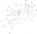
图1为本实用新型的立体结构示意图;Fig. 1 is the three-dimensional structure schematic diagram of the present utility model;
图2为本实用新型的定模连接结构示意图;Fig. 2 is a schematic diagram of the fixed mold connection structure of the present utility model;
图3为本实用新型的原料箱连接爆炸结构示意图;Fig. 3 is a schematic diagram of the connection explosion structure of the raw material box of the present invention;
图4为本实用新型的动模连接爆炸结构示意图。Fig. 4 is a schematic diagram of the explosion structure of the movable mold connection of the present invention.
其中:11、工作台;12、燕尾槽;13、底板;14、定模;15、第一模腔;16、固定框架;17、螺旋给料筒;21、支撑板;22、原料箱;23、插孔;24、插柱;25、盖板;26、分隔板;31、动模;32、燕尾块;33、第二模腔;34、第一顶出槽;35、第一柱槽;36、第二顶出槽;37、第二柱槽;41、固定块;42、中心柱;43、第一顶盘;44、活动柱;45、弹簧;46、固定环;47、第二顶盘。Among them: 11. Workbench; 12. Dovetail groove; 13. Bottom plate; 14. Fixed mold; 15. First mold cavity; 16. Fixed frame; 17. Spiral feeding barrel; 21. Support plate; 22. Raw material box; 23. Jack; 24. Inserting column; 25. Cover plate; 26. Partition plate; 31. Moving mold; 32. Dovetail block; 33. Second cavity; 34. First ejection groove; 35. First Column groove; 36, second ejection groove; 37, second column groove; 41, fixed block; 42, central column; 43, first top plate; 44, movable column; 45, spring; 46, fixed ring; 47 , the second top plate.
具体实施方式Detailed ways
为了使本实用新型实现的技术手段、创作特征、达成目的与功效易于明白了解,下面结合具体实施例,进一步阐述本实用新型,但下述实施例仅仅为本实用新型的优选实施例,并非全部。基于实施方式中的实施例,本领域技术人员在没有做出创造性劳动的前提下所获得其它实施例,都属于本实用新型的保护范围。下述实施例中的实验方法,如无特殊说明,均为常规方法,下述实施例中所用的材料、试剂等,如无特殊说明,均可从商业途径得到。In order to make the technical means, creative features, goals and effects of the utility model realized easy to understand, the utility model will be further elaborated below in conjunction with specific examples, but the following examples are only preferred embodiments of the utility model, not all . Based on the examples in the implementation manners, other examples obtained by those skilled in the art without making creative efforts all belong to the protection scope of the present utility model. The experimental methods in the following examples, unless otherwise specified, are conventional methods, and the materials, reagents, etc. used in the following examples, unless otherwise specified, can be obtained from commercial sources.
实施例:Example:
如图1、图2、图3和图4所示,一种汽车塑胶件单腔双射模具结构,包括工作台11,工作台11上端部对称开设有燕尾槽12,工作台11下端部固定安装有底板13,工作台11上端部固定安装有定模14,定模14侧壁上开设有第一模腔15,定模14前端设置有固定框架16,固定框架16内部对称设置有螺旋给料筒17,两个螺旋给料筒17注射口均内设在定模14中且与第一模腔15相连通;As shown in Figure 1, Figure 2, Figure 3 and Figure 4, a single-cavity double-shot mold structure for automotive plastic parts includes a
工作台11上端部固定安装有上料机构;The upper end of the
上料机构包括支撑板21,两个支撑板21均与工作台11固定连接,两个支撑板21之间固定安装有原料箱22,原料箱22上端部四角处均开设有插孔23,四个插孔23内部均滑动安装有插柱24,四个插柱24上端部固定安装有盖板25,原料箱22内壁中固定安装有分隔板26,使用时先向原料箱22内部注入两种颜色的原料,此时两种原料在分隔板26的作用下被分隔,此时将插柱24插入插孔23中,通过盖板25完成密封,当设备作业时,此时两种原料分别通过27和28注入两个螺旋给料筒17中,再通过螺旋给料筒17注入第一模腔15内部,此时在第一模腔15和第二模腔33内部注满成型,使得该设备在使用时可完成两种原料的有效分离射较,有效避免了工件的转移注胶,减少了模具的使用,提高了生产效率;Feeding mechanism comprises
定模14后端设置有脱模机构;The rear end of the fixed
脱模机构包括动模31,动模31与工作台11和定模14均活动连接,动模31下端部对称固定安装有燕尾块32,两个燕尾块32分别滑动安装在两个燕尾槽12中,动模31与定模14相对的一端上开设有第二模腔33,第二模腔33内壁中部开设有第一顶出槽34,第一顶出槽34内壁中部开设有第一柱槽35,第二模腔33内壁外围开设有第二顶出槽36,第二顶出槽36内壁中均匀等距开设有第二柱槽37,动模31后端设置有固定块41,固定块41与工作台11固定连接,固定块41侧壁中部固定安装有中心柱42,中心柱42远离固定块41的一端上固定安装有第一顶盘43,第一顶盘43和中心柱42分别活动内设在第一顶出槽34和第一柱槽35中,固定块41内部滑动安装有活动柱44,四个活动柱44表面均活动套设有弹簧45,四个活动柱44表面上均固定套设有固定环46,四个活动柱44两端分别与固定块41和固定环46固定连接,活动柱44远离固定块41的一端固定安装有第二顶盘47,活动柱44和第二顶盘47分别滑动内设在第二柱槽37和第二顶出槽36中,待得模具冷却后,此时可向后移动动模31,在动模31的移动下将带动与之固定的燕尾块32在燕尾槽12内部发生滑动,此时在动模31的移动下将带动中心柱42和第一顶盘43分别在第一柱槽35和第一顶出槽34内部滑动,此时第一顶盘43对模具进行初步顶出让其松动,随着动模31的持续移动,此时第二顶盘47对活动柱44施加向后的作用力,此时活动柱44在固定块41内部发生滑动,在活动柱44的滑动下将带动与之固定的固定环46发生滑动,此时固定环46挤压弹簧45产生压缩,当弹簧45压缩至最大值时,此时固定环46被固定块41限制无法移动,然后活动柱44和第二顶盘47在第二柱槽37和第二顶出槽36内部发生滑动对模具进行再次施力,在两次顶出力的作用下完成脱模,其有效增大了脱模时的顶出面积,使得脱模不易发生粘连且便捷度更高。The demoulding mechanism includes a
工作原理:working principle:
第一步:使用时先向原料箱22内部注入两种颜色的原料,此时两种原料在分隔板26的作用下被分隔,此时将插柱24插入插孔23中,通过盖板25完成密封,当设备作业时,此时两种原料分别通过27和28注入两个螺旋给料筒17中,再通过螺旋给料筒17注入第一模腔15内部,此时在第一模腔15和第二模腔33内部注满成型,使得该设备在使用时可完成两种原料的有效分离射较,有效避免了工件的转移注胶,减少了模具的使用,提高了生产效率。The first step: when using, first inject two colors of raw materials into the
第二步:待得模具冷却后,此时可向后移动动模31,在动模31的移动下将带动与之固定的燕尾块32在燕尾槽12内部发生滑动,此时在动模31的移动下将带动中心柱42和第一顶盘43分别在第一柱槽35和第一顶出槽34内部滑动,此时第一顶盘43对模具进行初步顶出让其松动,随着动模31的持续移动,此时第二顶盘47对活动柱44施加向后的作用力,此时活动柱44在固定块41内部发生滑动,在活动柱44的滑动下将带动与之固定的固定环46发生滑动,此时固定环46挤压弹簧45产生压缩,当弹簧45压缩至最大值时,此时固定环46被固定块41限制无法移动,然后活动柱44和第二顶盘47在第二柱槽37和第二顶出槽36内部发生滑动对模具进行再次施力,在两次顶出力的作用下完成脱模,其有效增大了脱模时的顶出面积,使得脱模不易发生粘连且便捷度更高。Step 2: After the mold is cooled, the
上面结合附图对本实用新型的实施方式作了详细说明,但是本实用新型并不限于此,在所属技术领域的技术人员所具备的知识范围内,在不脱离本实用新型宗旨的前提下还可以作出各种变化。Above, the embodiment of the present utility model has been described in detail in conjunction with the accompanying drawings, but the present utility model is not limited thereto. Make various changes.
Claims (6)
Priority Applications (1)
| Application Number | Priority Date | Filing Date | Title |
|---|---|---|---|
| CN202221460390.7U CN217834534U (en) | 2022-06-10 | 2022-06-10 | Single-cavity double-injection mold structure for automobile plastic part |
Applications Claiming Priority (1)
| Application Number | Priority Date | Filing Date | Title |
|---|---|---|---|
| CN202221460390.7U CN217834534U (en) | 2022-06-10 | 2022-06-10 | Single-cavity double-injection mold structure for automobile plastic part |
Publications (1)
| Publication Number | Publication Date |
|---|---|
| CN217834534U true CN217834534U (en) | 2022-11-18 |
Family
ID=84024409
Family Applications (1)
| Application Number | Title | Priority Date | Filing Date |
|---|---|---|---|
| CN202221460390.7U Active CN217834534U (en) | 2022-06-10 | 2022-06-10 | Single-cavity double-injection mold structure for automobile plastic part |
Country Status (1)
| Country | Link |
|---|---|
| CN (1) | CN217834534U (en) |
-
2022
- 2022-06-10 CN CN202221460390.7U patent/CN217834534U/en active Active
Similar Documents
| Publication | Publication Date | Title |
|---|---|---|
| CN113510900A (en) | A bucket injection mold for in-mold rapid prototyping | |
| CN218928475U (en) | Plastic injection mold | |
| CN215849392U (en) | Novel plastic mould | |
| CN215039799U (en) | A bucket injection mold for in-mold rapid prototyping | |
| CN211591064U (en) | Double-color mold for single-color injection molding machine | |
| CN221048962U (en) | Air guide pipe forming die | |
| CN114939641B (en) | A molding die | |
| CN215396856U (en) | Plastic uptake mould cylinder slider formula demoulding mechanism | |
| CN219095812U (en) | Injection molding device | |
| CN110919969B (en) | Two-color mold for single-color injection molding machine | |
| CN212826439U (en) | Dense rubber plastic tableware mould convenient to ejection of compact | |
| CN212219105U (en) | Mold equipment capable of achieving double-color injection molding | |
| CN211030999U (en) | Injection mold convenient for demolding | |
| CN221392055U (en) | Injection mold suitable for ejecting product with poor fluidity | |
| CN218593610U (en) | Simple and convenient secondary ejection structure | |
| CN208497587U (en) | Molded Depth glue position secondary demolding mechanism after a kind of | |
| CN223775978U (en) | A die casting mold | |
| CN217670762U (en) | Novel slider oblique top formula mould | |
| CN211993999U (en) | Injection mold for anti-electric shock ferrule socket | |
| CN219338435U (en) | Side-taking injection mold | |
| CN215434772U (en) | Mould is made to rubber toolbox | |
| CN219466837U (en) | Key forming die | |
| CN222290871U (en) | Injection mold easy to demolding | |
| CN222662501U (en) | Novel plastic spring mold structure with four-sided sliding blocks | |
| CN222768807U (en) | Forming die convenient to drawing of patterns |
Legal Events
| Date | Code | Title | Description |
|---|---|---|---|
| GR01 | Patent grant | ||
| GR01 | Patent grant |