CN217834197U - Concrete unloader - Google Patents
Concrete unloader Download PDFInfo
- Publication number
- CN217834197U CN217834197U CN202221875767.5U CN202221875767U CN217834197U CN 217834197 U CN217834197 U CN 217834197U CN 202221875767 U CN202221875767 U CN 202221875767U CN 217834197 U CN217834197 U CN 217834197U
- Authority
- CN
- China
- Prior art keywords
- fixed
- wall
- shaft body
- concrete
- bevel gear
- Prior art date
- Legal status (The legal status is an assumption and is not a legal conclusion. Google has not performed a legal analysis and makes no representation as to the accuracy of the status listed.)
- Active
Links
Images


Landscapes
- On-Site Construction Work That Accompanies The Preparation And Application Of Concrete (AREA)
Abstract
本实用新型公开了一种混凝土下料装置,属于混凝土技术领域,针对了现有混凝土进行生产搅拌时,搅拌完成后,需要对混凝土进行下料处理,但是在下料过程中,下料箱内侧壁容易残留混凝土,导致下料不充分的问题,包括下料箱,下料箱的底端内壁固定有对称设置的卸料板,卸料板的顶端侧壁为倾斜结构,卸料板的顶端侧壁转动连接有第一轴体;本实用新型通过设置的驱动电机、第三轴体、第二轴体以及循环板、敲打块、复位弹簧的配合,能够快速对下料箱的外侧壁进行循环敲打处理,能够对下料箱内侧壁残留的原料进行往复敲打,使原料从出料管排出,同时能够在循环敲打过程中,自动带动搅拌叶进行循环搅拌,提高了下料效果。
The utility model discloses a concrete blanking device, which belongs to the technical field of concrete, aiming at that when the existing concrete is produced and stirred, after the stirring is completed, the concrete needs to be unloaded, but during the unloading process, the inner wall of the unloading box It is easy to leave concrete, which leads to the problem of insufficient blanking, including the blanking box, the bottom inner wall of the blanking box is fixed with a symmetrically arranged unloading plate, the top side wall of the unloading plate is an inclined structure, and the top side of the unloading plate The wall is rotatably connected with the first shaft body; the utility model can quickly circulate the outer wall of the feeding box through the cooperation of the set drive motor, the third shaft body, the second shaft body, the circulation plate, the knocking block and the return spring. The beating process can reciprocate and beat the remaining raw materials on the inner wall of the feeding box, so that the raw materials can be discharged from the discharge pipe. At the same time, it can automatically drive the stirring blades for circulating stirring during the cycle beating process, which improves the feeding effect.
Description
技术领域technical field
本实用新型属于混凝土技术领域,具体涉及一种混凝土下料装置。The utility model belongs to the technical field of concrete, in particular to a concrete feeding device.
背景技术Background technique
混凝土(Concrete),简称为"砼(tóng)":是指由胶凝材料将集料胶结成整体的工程复合材料的统称。通常讲的混凝土一词是指用水泥作胶凝材料,砂、石作集料;与水(可含外加剂和掺合料)按一定比例配合,经搅拌而得的水泥混凝土,也称普通混凝土,它广泛应用于土木工程Concrete, referred to as "concrete (tóng)": refers to the collective name of engineering composite materials in which aggregates are cemented into a whole by cementitious materials. Generally speaking, the term concrete refers to the cement concrete obtained by using cement as the cementitious material, sand and stone as the aggregate; mixed with water (may contain admixtures and admixtures) in a certain proportion, and stirred. Concrete, which is widely used in civil engineering
凝土是当代最主要的土木工程材料之一。它是由胶凝材料,颗粒状集料(也称为骨料),水,以及必要时加入的外加剂和掺合料按一定比例配制,经均匀搅拌,密实成型,养护硬化而成的一种人工石材,现有混凝土进行生产搅拌时,搅拌完成后,需要对混凝土进行下料处理,但是在下料过程中,下料箱内侧壁容易残留混凝土,导致下料不充分,为此,我们提出了一种混凝土下料装置。Concrete is one of the most important civil engineering materials in contemporary times. It is composed of cementitious materials, granular aggregates (also known as aggregates), water, and additives and admixtures added when necessary, prepared in a certain proportion, uniformly stirred, densely formed, cured and hardened. A kind of artificial stone, when the existing concrete is produced and mixed, after the mixing is completed, the concrete needs to be unloaded. However, during the unloading process, the inner wall of the unloading box is prone to residual concrete, resulting in insufficient unloading. Therefore, we propose A concrete feeding device was developed.
实用新型内容Utility model content
本实用新型的目的在于提供一种混凝土下料装置,以解决上述背景技术中提出的问题。The purpose of this utility model is to provide a concrete cutting device to solve the problems raised in the above-mentioned background technology.
为实现上述目的,本实用新型提供如下技术方案:一种混凝土下料装置,包括下料箱,所述下料箱的底端内壁固定有对称设置的卸料板,所述卸料板的顶端侧壁为倾斜结构,所述卸料板的顶端侧壁转动连接有第一轴体,第一轴体的外侧壁固定有多个平行分布的搅拌叶,所述第一轴体的顶端固定有锥齿轮一,所述下料箱的底端侧壁正中间固定有出料管,所述出料管上固定有下料阀,所述下料箱的底端侧壁固定有对称设置的支撑座,所述支撑座与下料箱之间垂直设置,所述下料箱的顶端侧壁固定有对称设置的连接座,所述连接座的一侧侧壁开设有左右贯穿的连接通道,所述连接通道的内侧壁转动连接有第二轴体,所述第二轴体的一端固定有锥齿轮二,所述锥齿轮二与锥齿轮一之间啮合传动连接。In order to achieve the above purpose, the utility model provides the following technical solutions: a concrete cutting device, including a cutting box, the inner wall of the bottom end of the cutting box is fixed with a symmetrically arranged stripping plate, and the top of the stripping plate is The side wall is an inclined structure, the top side wall of the discharge plate is rotatably connected with a first shaft body, the outer side wall of the first shaft body is fixed with a plurality of parallel distributed stirring blades, and the top end of the first shaft body is fixed with a Bevel gear one, a discharge pipe is fixed in the middle of the bottom side wall of the discharge box, a discharge valve is fixed on the discharge pipe, and symmetrically arranged supports are fixed on the bottom side wall of the discharge box Seat, the support seat and the feeding box are vertically arranged, the top side wall of the feeding box is fixed with a symmetrically arranged connecting seat, and the side wall of the connecting seat is provided with a connecting channel penetrating left and right, so The inner side wall of the connecting channel is rotatably connected with a second shaft body, and one end of the second shaft body is fixed with a
方案中需要说明的是,所述连接座相互远离的一侧侧壁固定有支撑板,所述支撑板的顶端侧壁固定有驱动电机,所述驱动电机的输出轴通过联轴器固定有第三轴体,所述第三轴体的外侧壁紧配合固定有锥齿轮三,所述第二轴体的另一端固定有锥齿轮四,所述锥齿轮三与锥齿轮四之间啮合传动连接。What needs to be explained in the solution is that a support plate is fixed on the side walls of the connecting seats away from each other, a drive motor is fixed on the top side wall of the support plate, and the output shaft of the drive motor is fixed with a second shaft through a coupling. Three-axis body, the outer wall of the third axis body is closely fitted with a bevel gear three, and the other end of the second axis body is fixed with a bevel gear four, and the bevel gear three and bevel gear four are engaged in transmission connection .
进一步值得说明的是,所述下料箱的两侧外壁固定有对称设置的固定板,所述固定板的顶端侧壁滑动连接有移动条,所述移动条的顶端侧壁固定有循环板,所述循环板靠近下料箱的一侧侧壁连接有多个敲打块,所述敲打块与循环板之间垂直设置。It is further worth noting that symmetrically arranged fixed plates are fixed on both sides of the outer walls of the feeding box, and a moving bar is slidably connected to the top side wall of the fixed plate, and a circulation plate is fixed on the top side wall of the moving bar. A plurality of knocking blocks are connected to the side wall of the circulating plate close to the feeding box, and the knocking blocks are vertically arranged between the circulating plate.
更进一步需要说明的是,所述固定板的顶端侧壁固定有固定块,所述固定块与固定板之间垂直设置,所述固定块与移动条之间平行设置。It should be further explained that, the top side wall of the fixed plate is fixed with a fixed block, the fixed block is vertically arranged between the fixed plate, and the fixed block is arranged parallel to the moving bar.
作为一种优选的实施方式,所述循环板的顶端侧壁沿其长度方向开设有循环槽,所述循环槽的两侧侧壁沿其长度方向开设有多个对称设置的循环齿条,所述第三轴体远离驱动电机的一端延伸至循环槽内部固定有不完全齿轮,所述不完全齿轮与循环齿条之间啮合传动连接。As a preferred embodiment, the top side wall of the circulation plate is provided with a circulation groove along its length direction, and the side walls on both sides of the circulation groove are provided with a plurality of symmetrically arranged circulation racks along its length direction, so The end of the third shaft body away from the driving motor extends to the interior of the circulation groove and an incomplete gear is fixed, and the incomplete gear is meshed with the circulation rack for transmission connection.
作为一种优选的实施方式,所述下料箱的一侧外侧壁开设有观察通道,所述观察通道与下料箱内部连通,所述观察通道的内侧壁连接有透明观察窗。As a preferred embodiment, an observation channel is opened on one side of the outer side wall of the feeding box, and the observation channel communicates with the inside of the feeding box, and a transparent observation window is connected to the inner side wall of the observation channel.
与现有技术相比,本实用新型提供的混凝土下料装置,至少包括如下有益效果:Compared with the prior art, the concrete cutting device provided by the utility model at least includes the following beneficial effects:
(1)通过设置的下料箱、卸料板、支撑座、出料管、下料阀、搅拌叶以及第一轴体的配合,能够快速对混凝土原料进行搅拌混合,能够在搅拌混合后快速进行出料,便于进行下料处理;(1) Through the cooperation of the set discharge box, discharge plate, support seat, discharge pipe, discharge valve, stirring blade and the first shaft body, the concrete raw materials can be quickly mixed, and the concrete raw materials can be quickly mixed after mixing. For discharging, it is convenient for unloading;
(2)通过设置的驱动电机、第三轴体、第二轴体以及循环板、敲打块、复位弹簧的配合,能够快速对下料箱的外侧壁进行循环敲打处理,能够对下料箱内侧壁残留的原料进行往复敲打,使原料从出料管排出,同时能够在循环敲打过程中,自动带动搅拌叶进行循环搅拌,提高了下料效果。(2) Through the cooperation of the set drive motor, the third shaft body, the second shaft body, the circulation plate, the knocking block, and the return spring, the outer wall of the unloading box can be quickly cyclically beaten, and the inner side of the unloading box can be knocked. The remaining raw materials on the wall are reciprocally beaten to make the raw materials discharged from the discharge pipe. At the same time, the stirring blades can be automatically driven to circulate and stir during the circular beating process, which improves the feeding effect.
附图说明Description of drawings
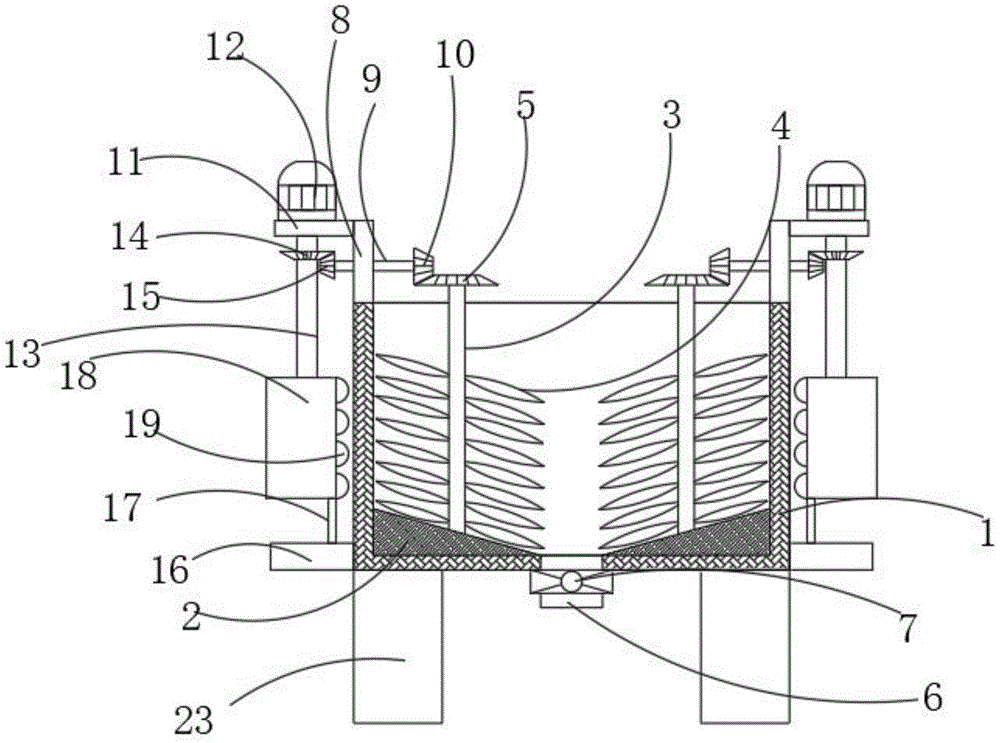
图1为本实用新型的结构主剖图;Fig. 1 is the structural main sectional drawing of the present utility model;
图2为本实用新型的循环板结构俯视图。Fig. 2 is a top view of the circulation plate structure of the present invention.
图中:1下料箱、2下料板、3第一轴体、4搅拌叶、5锥齿轮一、6出料管、7下料阀、8连接座、9第二轴体、10锥齿轮二、11支撑板、12驱动电机、13第三轴体、14锥齿轮三、15锥齿轮四、16固定板、17移动条、18循环板、19敲打块、20循环槽、21循环齿条、22不完全齿轮、23支撑座。In the figure: 1 feeding box, 2 feeding plate, 3 first shaft body, 4 stirring blade, 5
具体实施方式Detailed ways
下面结合实施例对本实用新型做进一步的描述。Below in conjunction with embodiment the utility model is described further.
为了使得本实用新型实施例的目的、技术方案和优点更加清楚,下面将结合本实用新型实施例的附图,对本实用新型实施例的技术方案进行清楚、完整地描述,显然,所描述的实施例是本实用新型的一部分实施例,而不是全部的实施例,基于所描述的本实用新型的实施例,本领域普通技术人员在无需创造性劳动的前提下所获得的所有其他实施例,都属于本实用新型保护的范围。In order to make the purposes, technical solutions and advantages of the embodiments of the utility model clearer, the technical solutions of the embodiments of the utility model will be clearly and completely described below in conjunction with the accompanying drawings of the embodiments of the utility model. Obviously, the described implementation The example is a part of the embodiments of the utility model, rather than all the embodiments. Based on the described embodiments of the utility model, all other embodiments obtained by those of ordinary skill in the art without creative work belong to The protection scope of the utility model.
以下实施例用于说明本实用新型,但不能用来限制本实用新型的保护范围。实施例中的条件可以根据具体条件做进一步的调整,在本实用新型的构思前提下对本实用新型的方法简单改进都属于本实用新型要求保护的范围。The following examples are used to illustrate the utility model, but can not be used to limit the protection scope of the utility model. The conditions in the embodiment can be further adjusted according to the specific conditions, and the simple improvement of the method of the utility model under the premise of the concept of the utility model belongs to the protection scope of the utility model.
请参阅图1-2,本实用新型提供一种混凝土下料装置,包括下料箱1,下料箱1的底端内壁固定有对称设置的卸料板,卸料板的顶端侧壁为倾斜结构,卸料板的顶端侧壁转动连接有第一轴体3,第一轴体3的外侧壁固定有多个平行分布的搅拌叶4,第一轴体3的顶端固定有锥齿轮一5,下料箱1的底端侧壁正中间固定有出料管6,出料管6上固定有下料阀7,下料箱1的底端侧壁固定有对称设置的支撑座23,支撑座23与下料箱1之间垂直设置,下料箱1的顶端侧壁固定有对称设置的连接座8,连接座8的一侧侧壁开设有左右贯穿的连接通道,连接通道的内侧壁转动连接有第二轴体9,第二轴体9的一端固定有锥齿轮二10,锥齿轮二10与锥齿轮一5之间啮合传动连接。Please refer to Figure 1-2, the utility model provides a concrete blanking device, including a blanking box 1, the inner wall of the bottom end of the blanking box 1 is fixed with a symmetrically arranged unloading plate, and the top side wall of the unloading plate is inclined structure, the top side wall of the unloading plate is rotatably connected with the
进一步地如图1、图2所示,方案中需要说明的是,连接座8相互远离的一侧侧壁固定有支撑板11,支撑板11的顶端侧壁固定有驱动电机12,驱动电机12的输出轴通过联轴器固定有第三轴体13,第三轴体13的外侧壁紧配合固定有锥齿轮三14,第二轴体9的另一端固定有锥齿轮四15,锥齿轮三14与锥齿轮四15之间啮合传动连接。Further as shown in Fig. 1 and Fig. 2, what needs to be explained in the scheme is that the side walls of the connecting
进一步地如图1、图2所示,进一步值得说明的是,下料箱1的两侧外壁固定有对称设置的固定板16,固定板16的顶端侧壁滑动连接有移动条17,移动条17的顶端侧壁固定有循环板18,循环板18靠近下料箱1的一侧侧壁连接有多个敲打块19,敲打块19与循环板18之间垂直设置。Further as shown in Fig. 1 and Fig. 2, it is further worth noting that the outer walls on both sides of the blanking box 1 are fixed with symmetrically arranged fixed
进一步地如图1、图2所示,更进一步需要说明的是,固定板16的顶端侧壁固定有固定块,固定块与固定板16之间垂直设置,固定块与移动条17之间平行设置。Further as shown in Fig. 1 and Fig. 2, it should be further noted that the top side wall of the
本方案具备以下工作过程:将混凝土原料倒入下料箱1内部,启动驱动电机12,驱动电机12带动第三轴体13进行旋转,第三轴体13带动锥齿轮三14进行旋转,锥齿轮三14与锥齿轮四15之间啮合传动带动第二轴体9进行旋转,第二轴体9带动锥齿轮二10进行旋转,锥齿轮二10与锥齿轮一5之间啮合传动带动第一轴体3进行旋转,第一轴体3带动搅拌叶4进行旋转,使搅拌叶4对混凝土原料进行搅拌混合,同时第三轴体13带动不完全齿轮22进行旋转,不完全齿轮22与循环齿条21之间啮合传动带动循环板18进行来回往复移动,循环板18带动敲打块19来回移动对下料箱1外侧壁进行循环敲打,对下料箱1内侧壁的原料进行持续敲落,通过打开下料阀7,对混凝土原料进行下料处理,通过下料板2的倾斜面使混凝土原料进行排出。This scheme has the following working process: pour the concrete raw materials into the lower material box 1, start the
进一步地如图1、图2所示,循环板18的顶端侧壁沿其长度方向开设有循环槽20,循环槽20的两侧侧壁沿其长度方向开设有多个对称设置的循环齿条21,第三轴体13远离驱动电机12的一端延伸至循环槽20内部固定有不完全齿轮22,不完全齿轮22与循环齿条21之间啮合传动连接,下料箱1的一侧外侧壁开设有观察通道,观察通道与下料箱1内部连通,观察通道的内侧壁连接有透明观察窗。Further as shown in Figures 1 and 2, the top side wall of the
除非另外定义,本实用新型使用的技术术语或者科学术语应当为本实用新型所属领域内具有一般技能的人士所理解的通常意义,本实用新型中使用的“包括”或者“包含”等类似的词语意指出现该词前面的元件或者物件涵盖出现在该词后面列举的元件或者物件及其等同,而不排除其他元件或者物件,“连接”或者“相连”等类似的词语并非限定于物理的或者机械的连接,还可以包括电性的连接,不管是直接的还是间接的,“上”、“下”、“左”、“右”等仅用于表示相对位置关系,当被描述对象的绝对位置改变后,则该相对位置关系也可能相应地改变。Unless otherwise defined, the technical terms or scientific terms used in this utility model should be the usual meanings understood by those with ordinary skill in the field of this utility model, and similar words such as "comprising" or "comprising" used in this utility model It means that the elements or objects appearing before the word include the elements or objects listed after the word and their equivalents, without excluding other elements or objects, and similar words such as "connect" or "connected" are not limited to physical or Mechanical connections can also include electrical connections, whether direct or indirect, "upper", "lower", "left", "right", etc. are only used to indicate relative positional relationships, when the absolute After the position changes, the relative positional relationship may also change accordingly.
尽管已经示出和描述了本实用新型的实施例,对于本领域的普通技术人员而言,可以理解在不脱离本实用新型的原理和精神的情况下可以对这些实施例进行多种变化、修改、替换和变型,本实用新型的范围由所附权利要求及其等同物限定。Although the embodiments of the present invention have been shown and described, those skilled in the art can understand that various changes and modifications can be made to these embodiments without departing from the principle and spirit of the present invention , replacements and modifications, the scope of the present utility model is defined by the appended claims and their equivalents.
Claims (6)
Priority Applications (1)
| Application Number | Priority Date | Filing Date | Title |
|---|---|---|---|
| CN202221875767.5U CN217834197U (en) | 2022-07-20 | 2022-07-20 | Concrete unloader |
Applications Claiming Priority (1)
| Application Number | Priority Date | Filing Date | Title |
|---|---|---|---|
| CN202221875767.5U CN217834197U (en) | 2022-07-20 | 2022-07-20 | Concrete unloader |
Publications (1)
| Publication Number | Publication Date |
|---|---|
| CN217834197U true CN217834197U (en) | 2022-11-18 |
Family
ID=84039839
Family Applications (1)
| Application Number | Title | Priority Date | Filing Date |
|---|---|---|---|
| CN202221875767.5U Active CN217834197U (en) | 2022-07-20 | 2022-07-20 | Concrete unloader |
Country Status (1)
| Country | Link |
|---|---|
| CN (1) | CN217834197U (en) |
Cited By (1)
| Publication number | Priority date | Publication date | Assignee | Title |
|---|---|---|---|---|
| CN117919574A (en) * | 2024-01-11 | 2024-04-26 | 中国人民解放军联勤保障部队第九〇四医院 | Stomach intestine medicine feeder |
-
2022
- 2022-07-20 CN CN202221875767.5U patent/CN217834197U/en active Active
Cited By (1)
| Publication number | Priority date | Publication date | Assignee | Title |
|---|---|---|---|---|
| CN117919574A (en) * | 2024-01-11 | 2024-04-26 | 中国人民解放军联勤保障部队第九〇四医院 | Stomach intestine medicine feeder |
Similar Documents
| Publication | Publication Date | Title |
|---|---|---|
| CN208576037U (en) | A kind of hand is from dual-purpose concrete mixer | |
| CN206855758U (en) | A kind of concrete for construction engineering mixer | |
| CN211640446U (en) | An energy-saving and environmentally friendly concrete mixing tank | |
| CN209903578U (en) | Municipal administration bridge face concrete mixing arrangement equipment | |
| CN220922857U (en) | Concrete feeding device | |
| CN210850798U (en) | Cement mixer with automatic feeding function | |
| CN205630988U (en) | Raw material mixing device for brickmaking | |
| CN217531332U (en) | Homogenizing equipment for composite cement production | |
| CN217346019U (en) | An automatic batching and homogenizing concrete production device | |
| CN212554411U (en) | Mortar mixer convenient to construction | |
| CN113232159B (en) | Commercial concrete mixing and conveying integrated system | |
| CN209775130U (en) | Concrete mixing device of bridge construction | |
| CN213533171U (en) | Concrete material processing equipment | |
| CN217573475U (en) | High-strength light concrete block production equipment | |
| CN216181632U (en) | High-efficient agitating unit of storable mortar | |
| CN214725277U (en) | Concrete mixing device | |
| CN219522536U (en) | Concrete admixture compound feeding device | |
| CN111978051A (en) | A kind of multifunctional foamed concrete and preparation method thereof | |
| CN217967653U (en) | Light gypsum that plasters homogenizes device convenient to ejection of compact | |
| CN218535120U (en) | A mud mixing equipment for permeable brick production | |
| CN223251982U (en) | Discharging equipment for processing steam-pressurized concrete building blocks | |
| CN217862045U (en) | Proportioning equipment for mortar concrete admixture | |
| CN216860154U (en) | Concrete mixing production facility for building engineering | |
| CN112895067A (en) | Concrete block forming machine | |
| CN221187021U (en) | Thermal insulation mortar raw material preparation device |
Legal Events
| Date | Code | Title | Description |
|---|---|---|---|
| GR01 | Patent grant | ||
| GR01 | Patent grant |