CN217832819U - Convenient positioning fixture for numerical control lathe - Google Patents
Convenient positioning fixture for numerical control lathe Download PDFInfo
- Publication number
- CN217832819U CN217832819U CN202221619003.XU CN202221619003U CN217832819U CN 217832819 U CN217832819 U CN 217832819U CN 202221619003 U CN202221619003 U CN 202221619003U CN 217832819 U CN217832819 U CN 217832819U
- Authority
- CN
- China
- Prior art keywords
- positioning
- gear
- fixture
- fixed
- numerically controlled
- Prior art date
- Legal status (The legal status is an assumption and is not a legal conclusion. Google has not performed a legal analysis and makes no representation as to the accuracy of the status listed.)
- Expired - Fee Related
Links
Images

Landscapes
- Machine Tool Units (AREA)
Abstract
本实用新型涉及车床技术领域,公开了一种数控车床用便于定位夹具,包括定位台,所述定位台的上表面中间位置设置有放料圈,所述定位台的下端设置有底座,所述定位台的上表面对称设置有两个固定座,所述固定座左右两侧均开设有滑槽,所述固定座的内侧中间位置设置有竖杆,所述竖杆的外侧滑动连接有移动板。通过可上下滑动的滑块,进而灵活控制气缸上下移动,从而能够更好的固定住所加工的零件,具有较高的适应性,通过电机带动第一齿轮转动,第一齿轮啮合带动第二齿轮转动,进而带动定位台转动,通过定位台的转动会将零件调整到更好的处理角度,不用重新调整夹具,便于人员处理,加快了工作效率。

The utility model relates to the technical field of lathes, and discloses a convenient positioning fixture for a numerically controlled lathe, comprising a positioning platform, a discharge ring is arranged at the middle position of the upper surface of the positioning platform, and a base is provided at the lower end of the positioning platform. The upper surface of the positioning platform is symmetrically provided with two fixed seats, the left and right sides of the fixed seats are provided with chute, the inner middle of the fixed seat is provided with a vertical bar, and the outer side of the vertical bar is slidingly connected with a moving plate . Through the sliding block that can slide up and down, the cylinder can be flexibly controlled to move up and down, so that the processed parts can be better fixed, and it has high adaptability. The motor drives the first gear to rotate, and the first gear meshes to drive the second gear to rotate. , and then drive the positioning table to rotate, through the rotation of the positioning table, the parts will be adjusted to a better processing angle, without readjusting the fixture, which is convenient for personnel to handle and speeds up the work efficiency.
Description
技术领域technical field
本实用新型涉及车床技术领域,具体是一种数控车床用便于定位夹具。The utility model relates to the technical field of lathes, in particular to a fixture for convenient positioning of a numerically controlled lathe.
背景技术Background technique
车床夹具是指在车床上用来加工零件内、外回转面及端面的夹具。车床夹具多数安装在主轴上,少数安装在床鞍或床身上,定位夹具可以实现对零件的夹紧工作,进而方便加工刀具对零件的加工,使得人员能够更精确、更便捷的进行加工生产。Lathe fixture refers to the fixture used to process the inner and outer rotary surfaces and end surfaces of parts on a lathe. Most of the lathe fixtures are installed on the main shaft, and a few are installed on the saddle or bed. The positioning fixture can realize the clamping work of the parts, and then facilitate the processing of the parts by the processing tool, so that the personnel can process and produce more accurately and conveniently.
中国专利公开了一种车床定位支撑装置(授权公告号CN206588614U),该专利技术包括定位台、夹持基座、底座、承接卡座和隔油圈,所述定位台上表面设有转轴环,且转轴环外表面套接有密封圈,所述定位台上表面两侧设有夹持基座,所述夹持基座内部设有夹持杆,且夹持杆一端固定有调节转柄,另一端固定有夹持片,该定位支撑装置在整体结构设计上比较简单,其定位支撑效果很明显,提高了该装置的实际使用价值,但是其不能调节夹具夹持的高度,不能灵活的固定住零件,因此,本领域技术人员提供了一种数控车床用便于定位夹具,以解决上述背景技术中提出的问题。A Chinese patent discloses a lathe positioning support device (authorized announcement number CN206588614U). The patented technology includes a positioning table, a clamping base, a base, a receiving card seat and an oil separator. The upper surface of the positioning table is provided with a rotating shaft ring. And the outer surface of the rotating shaft ring is sleeved with a sealing ring, the upper surface of the positioning platform is provided with a clamping base on both sides, the clamping base is provided with a clamping rod, and one end of the clamping rod is fixed with an adjusting handle. The other end is fixed with a clamping piece. The positioning support device is relatively simple in overall structural design, and its positioning support effect is obvious, which improves the actual use value of the device. However, it cannot adjust the clamping height of the clamp and cannot be fixed flexibly. Therefore, those skilled in the art provide a convenient positioning fixture for CNC lathes to solve the problems raised in the background technology above.
实用新型内容Utility model content
本实用新型的目的在于提供一种数控车床用便于定位夹具,以解决上述背景技术中提出的问题。The purpose of this utility model is to provide a convenient positioning fixture for a numerically controlled lathe to solve the problems raised in the above-mentioned background technology.
为实现上述目的,本实用新型提供如下技术方案:In order to achieve the above object, the utility model provides the following technical solutions:
一种数控车床用便于定位夹具,包括定位台,所述定位台的上表面中间位置设置有放料圈,所述定位台的下端设置有底座,所述定位台的上表面对称设置有两个固定座,所述固定座左右两侧均开设有滑槽,所述固定座的内侧中间位置设置有竖杆,所述竖杆的外侧滑动连接有移动板,所述移动板的前后端均固定连接有滑块,所述滑槽的外侧设置有固定板,所述滑块的一端设置有螺栓,所述移动板的一端设置有气缸,所述气缸的一端设置有夹爪,所述底座的内部位于定位台的下方对称设置有两个支撑杆,所述支撑杆的下端连接有旋转盘,所述旋转盘中心位置的下端设置有旋转杆,所述旋转杆的下端设置有轴承,所述旋转杆的外部安装有第二齿轮。A convenient positioning fixture for a numerically controlled lathe, comprising a positioning platform, a material discharge ring is arranged in the middle of the upper surface of the positioning platform, a base is provided at the lower end of the positioning platform, and two symmetrically arranged on the upper surface of the positioning platform. The fixed seat, the left and right sides of the fixed seat are provided with chute, the inner middle of the fixed seat is provided with a vertical bar, the outer side of the vertical bar is slidingly connected with a moving plate, and the front and rear ends of the moving plate are fixed A slider is connected, a fixed plate is provided on the outside of the chute, a bolt is provided at one end of the slider, a cylinder is provided at one end of the moving plate, a jaw is provided at one end of the cylinder, and a clamp is provided at one end of the base. There are two support rods arranged symmetrically below the positioning platform inside, the lower end of the support rods is connected with a rotating disk, the lower end of the center of the rotating disk is provided with a rotating rod, and the lower end of the rotating rod is provided with a bearing. A second gear is installed on the outside of the rotating rod.
作为本实用新型再进一步的方案:所述固定板的一侧靠近滑槽的位置上均匀设置有多个螺孔,所述滑块与固定板通过螺栓和螺孔固定连接。As a further solution of the present invention: a plurality of screw holes are uniformly arranged on one side of the fixing plate close to the chute, and the slider and the fixing plate are fixedly connected by bolts and screw holes.
作为本实用新型再进一步的方案:所述滑块贯穿滑槽的内侧,所述滑槽与滑块滑动连接。As a further solution of the utility model: the slider runs through the inner side of the chute, and the chute is slidably connected with the slider.
作为本实用新型再进一步的方案:所述轴承安装于底座的内侧底部。As a further solution of the utility model: the bearing is installed on the inner bottom of the base.
作为本实用新型再进一步的方案:所述底座内侧底部设置有电机,所述电机的输出端设置有第一齿轮。As a further solution of the present invention: a motor is provided at the inner bottom of the base, and a first gear is provided at the output end of the motor.
作为本实用新型再进一步的方案:所述第一齿轮与第二齿轮啮合连接。As a further solution of the present invention: the first gear is meshed with the second gear.
与现有技术相比,本实用新型的有益效果:Compared with the prior art, the utility model has the beneficial effects:
1、通过滑块在滑槽上竖直滑动,使得移动板在固定座内滑动,通过螺栓与螺孔使得滑块固定在固定板上,通过可上下滑动的滑块,进而灵活控制气缸上下移动,从而能够更好的固定住所加工的零件,具有较高的适应性。1. The sliding block slides vertically on the chute, so that the moving plate slides in the fixed seat, and the sliding block is fixed on the fixed plate through bolts and screw holes. Through the sliding block that can slide up and down, the cylinder can be flexibly controlled to move up and down , so as to better fix the processed parts and have high adaptability.
2、通过电机带动第一齿轮转动,第一齿轮啮合带动第二齿轮转动,进而带动定位台转动,通过定位台的转动会将零件调整到更好的处理角度,不用重新调整夹具,便于人员处理,加快了工作效率。2. The motor drives the first gear to rotate, the first gear meshes to drive the second gear to rotate, and then drives the positioning table to rotate, and the rotation of the positioning table will adjust the parts to a better processing angle, without readjusting the fixture, which is convenient for personnel to handle , to speed up work efficiency.
附图说明Description of drawings
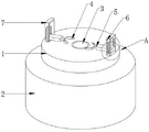
图1为一种数控车床用便于定位夹具的结构示意图;Fig. 1 is the structural schematic diagram that a kind of numerical control lathe is convenient to locate fixture;
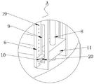
图2为一种数控车床用便于定位夹具中A的放大示意图;Fig. 2 is an enlarged schematic diagram of A in the positioning fixture for a kind of numerical control lathe;
图3为一种数控车床用便于定位夹具中底座的内部示意图。Fig. 3 is an internal schematic diagram of a base in a fixture for easy positioning of a numerically controlled lathe.
图中:1、定位台;2、底座;3、放料圈;4、夹爪;5、气缸;6、固定板;7、固定座;8、竖杆;9、滑槽;10、滑块;11、移动板;12、旋转盘;13、支撑杆;14、第一齿轮;15、第二齿轮;16、旋转杆;17、电机;18、轴承;19、螺孔;20、螺栓。In the figure: 1. Positioning platform; 2. Base; 3. Discharge ring; 4. Gripper; 5. Cylinder; 6. Fixing plate; 7. Fixing seat; 8. Vertical bar; Block; 11, moving plate; 12, rotating disc; 13, support rod; 14, first gear; 15, second gear; 16, rotating rod; 17, motor; 18, bearing; 19, screw hole; 20, bolt .
具体实施方式Detailed ways
请参阅图1~3,本实用新型实施例中,一种数控车床用便于定位夹具,包括定位台1,定位台1的上表面中间位置设置有放料圈3,定位台1的下端设置有底座2,定位台1的上表面对称设置有两个固定座7,固定座7左右两侧均开设有滑槽9,固定座7的内侧中间位置设置有竖杆8,通过竖杆8对移动板11进行支撑、限位,从而可以使得移动板11在固定座7的内部平稳地上下滑动,竖杆8的外侧滑动连接有移动板11,移动板11的前后端均固定连接有滑块10,滑槽9的外侧设置有固定板6,滑块10的一端设置有螺栓20,移动板11的一端设置有气缸5,气缸5的一端设置有夹爪4,底座2的内部位于定位台1的下方对称设置有两个支撑杆13,支撑杆13的下端连接有旋转盘12,旋转盘12中心位置的下端设置有旋转杆16,旋转杆16的下端设置有轴承18,通过轴承18对旋转杆16进行支撑、限位,从而可以使得旋转盘12平稳地转动,旋转杆16的外部安装有第二齿轮15。Please refer to Fig. 1-3, in the embodiment of the present utility model, a kind of numerical control lathe is used for convenient positioning jig, comprises
在图1和2中,固定板6的一侧靠近滑槽9的位置上均匀设置有多个螺孔19,滑块10与固定板6通过螺栓20和螺孔19固定连接,螺栓20与螺孔19固定使得滑块10固定在固定板6上,滑块10贯穿滑槽9的内侧,滑槽9与滑块10滑动连接,通过可上下滑动的滑块10,可灵活控制气缸5上下移动,能够更好的固定住所加工的零件,具有较高的适应性。In Figures 1 and 2, a plurality of
在图3中,轴承18安装于底座2的内侧底部,底座2内侧底部设置有电机17,电机17的输出端设置有第一齿轮14,第一齿轮14与第二齿轮15啮合连接,通过电机17带动第一齿轮14转动,第一齿轮14啮合带动第二齿轮15转动,第二齿轮15带动旋转杆16转动,旋转杆16带动旋转盘12转动,旋转盘12转动从而带动定位台1,实现了加工角度的偏转,有利于对零件的处理,不用再调整夹具,加快了工作效率。In Fig. 3, the
本实用新型的工作原理:Working principle of the utility model:
在使用该夹具时,首先将零件放置于放料圈3上,通过观测,拧松螺栓20,控制滑块10在滑槽9上竖直滑动,从而使得移动板11在固定座7内滑动,将气缸5调节到合适的位置,拧紧螺栓20,使得螺栓20与螺孔19固定使得滑块10固定在固定板6上,在控制气缸5伸缩,两侧夹爪4伸出,将零件夹紧,进而固定住,通过可上下滑动的滑块10,可灵活控制气缸5上下移动,能够更好的固定住所加工的零件,具有较高的适应性。When using the clamp, first place the parts on the discharge ring 3, and through observation, unscrew the
当零件的加工角度不太适合时,启动电机17启动,带动第一齿轮14转动,第一齿轮14啮合带动第二齿轮15转动,第二齿轮15带动旋转杆16转动,旋转杆16带动旋转盘12转动,旋转盘12转动从而带动定位台1,通过定位台1的转动会将零件调整到更好的处理角度,不用重新调整夹具,便于人员处理,加快了工作效率。When the processing angle of the part is not suitable, the
以上所述的,仅为本实用新型较佳的具体实施方式,但本实用新型的保护范围并不局限于此,任何熟悉本技术领域的技术人员在本实用新型揭露的技术范围内,根据本实用新型的技术方案及其实用新型构思加以等同替换或改变,都应涵盖在本实用新型的保护范围之内。The above is only a preferred embodiment of the utility model, but the scope of protection of the utility model is not limited thereto. Any equivalent replacement or change of the technical solution of the utility model and the concept of the utility model shall be covered by the protection scope of the utility model.
Claims (6)
Priority Applications (1)
| Application Number | Priority Date | Filing Date | Title |
|---|---|---|---|
| CN202221619003.XU CN217832819U (en) | 2022-06-27 | 2022-06-27 | Convenient positioning fixture for numerical control lathe |
Applications Claiming Priority (1)
| Application Number | Priority Date | Filing Date | Title |
|---|---|---|---|
| CN202221619003.XU CN217832819U (en) | 2022-06-27 | 2022-06-27 | Convenient positioning fixture for numerical control lathe |
Publications (1)
| Publication Number | Publication Date |
|---|---|
| CN217832819U true CN217832819U (en) | 2022-11-18 |
Family
ID=84026981
Family Applications (1)
| Application Number | Title | Priority Date | Filing Date |
|---|---|---|---|
| CN202221619003.XU Expired - Fee Related CN217832819U (en) | 2022-06-27 | 2022-06-27 | Convenient positioning fixture for numerical control lathe |
Country Status (1)
| Country | Link |
|---|---|
| CN (1) | CN217832819U (en) |
Cited By (1)
| Publication number | Priority date | Publication date | Assignee | Title |
|---|---|---|---|---|
| CN121042582A (en) * | 2025-11-03 | 2025-12-02 | 南通海润机床有限公司 | A processing head and a processing machine tool |
-
2022
- 2022-06-27 CN CN202221619003.XU patent/CN217832819U/en not_active Expired - Fee Related
Cited By (1)
| Publication number | Priority date | Publication date | Assignee | Title |
|---|---|---|---|---|
| CN121042582A (en) * | 2025-11-03 | 2025-12-02 | 南通海润机床有限公司 | A processing head and a processing machine tool |
Similar Documents
| Publication | Publication Date | Title |
|---|---|---|
| CN222058912U (en) | Drilling seat of numerical control lathe | |
| CN120862349A (en) | Turning and milling combined type numerical control machine tool | |
| CN212726805U (en) | Working clamp for machining motor end cover | |
| CN116690343B (en) | Grinding equipment for building stone and working method thereof | |
| CN218017330U (en) | Six-station rotary table turning and milling composite all-in-one machine | |
| CN112828764B (en) | Floating self-centering clamp for valve sleeve honing | |
| CN113146593B (en) | Swing arm type mechanical arm | |
| CN218575647U (en) | Multi-station machining equipment capable of synchronously overturning | |
| CN217800170U (en) | Milling and grinding combined integrated numerical control machine tool | |
| CN117001037A (en) | Boring processing table capable of processing multi-bearing seat and processing method thereof | |
| CN221066178U (en) | Adjustable supporting device for precision machining | |
| CN224102398U (en) | Positioning fixture device for machining based on multidirectional adjustment | |
| CN219094863U (en) | Clamp for machining automobile front wheel cover | |
| CN108161137B (en) | Grinding machine for machining workpieces having a rack-like peripheral edge | |
| CN106964804B (en) | Reaming device | |
| CN218082608U (en) | Rotatable machining platform for machining | |
| CN223811784U (en) | Six-axis automatic screw locking machine | |
| CN223557939U (en) | Vertical machining center is with feeding pusher | |
| CN112621599A (en) | Efficient workpiece clamp capable of adjusting clamping radius for machining | |
| CN223776052U (en) | A drilling device for machining | |
| CN223989487U (en) | Sculpture design workstation | |
| CN221047335U (en) | A clamp for chuck that is easy to adjust | |
| CN120755703B (en) | Milling equipment for machining bearing end cover surface | |
| CN220145279U (en) | A circuit breaker housing machining fixture | |
| CN221290859U (en) | Auxiliary tool clamp for machining wear-resisting blocks |
Legal Events
| Date | Code | Title | Description |
|---|---|---|---|
| GR01 | Patent grant | ||
| GR01 | Patent grant | ||
| CF01 | Termination of patent right due to non-payment of annual fee |
Granted publication date: 20221118 |
|
| CF01 | Termination of patent right due to non-payment of annual fee |