CN217809819U - A kind of slubbing equipment for lightweight wool blended yarn - Google Patents
A kind of slubbing equipment for lightweight wool blended yarn Download PDFInfo
- Publication number
- CN217809819U CN217809819U CN202221373675.7U CN202221373675U CN217809819U CN 217809819 U CN217809819 U CN 217809819U CN 202221373675 U CN202221373675 U CN 202221373675U CN 217809819 U CN217809819 U CN 217809819U
- Authority
- CN
- China
- Prior art keywords
- carding
- roller
- vertical plate
- base
- electric cylinder
- Prior art date
- Legal status (The legal status is an assumption and is not a legal conclusion. Google has not performed a legal analysis and makes no representation as to the accuracy of the status listed.)
- Expired - Fee Related
Links
Images



Landscapes
- Preliminary Treatment Of Fibers (AREA)
Abstract
本实用新型公开了一种轻量化羊毛混纺纱用粗纺设备,包括底座、立板、第一梳理辊、第二梳理辊和收卷辊,所述第一梳理辊和第二梳理辊外围分别设置有粗齿和细齿,所述立板一侧靠近所述第一梳理辊与第二梳理辊之间处通过螺钉安装有第一伺服电缸,所述立板一侧靠近所述第二梳理辊下端处通过螺钉安装有第二伺服电缸,所述第一伺服电缸和第二伺服电缸的动力输出端均连接有U形连接块,所述U形连接块内侧通过螺钉安装有条形块,所述条形块端部设置有梳理齿。该新型不但具备转动的梳理结构,还具备插入式梳理结构,在粗纺后羊毛丝中的剩余杂质较少,适合广泛推广使用。
The utility model discloses a roving equipment for lightweight wool blended yarn, which comprises a base, a vertical plate, a first carding roller, a second carding roller and a winding roller, and the peripheries of the first carding roller and the second carding roller are respectively Coarse teeth and fine teeth are provided, and a first servo electric cylinder is installed on one side of the vertical plate close to the first combing roller and the second combing roller through screws, and one side of the vertical plate is close to the second combing roller. The lower end of the carding roller is installed with a second servo electric cylinder through screws, and the power output ends of the first servo electric cylinder and the second servo electric cylinder are connected with a U-shaped connecting block, and the inside of the U-shaped connecting block is installed with a screw. The strip block is provided with combing teeth at the end of the strip block. This new type not only has a rotating carding structure, but also has an inserting carding structure, and the remaining impurities in the wool yarn after woolen are less, which is suitable for widespread promotion and use.
Description
技术领域technical field
本实用新型涉及纺织技术领域,特别涉及一种轻量化羊毛混纺纱用粗纺设备。The utility model relates to the technical field of textiles, in particular to a slubbing device for lightweight wool blended yarn.
背景技术Background technique
在羊毛纺织中,为了在混纺前对羊毛进行粗纺,所以粗纺设备是十分必要的。In wool weaving, wool spinning equipment is necessary in order to woolen wool before blending.
以往的粗纺设备存在以下缺点:1、只具备转动的梳理结构,在粗纺后羊毛丝中的剩余杂质较多。为此,我们提出一种轻量化羊毛混纺纱用粗纺设备。The previous roving equipment has the following disadvantages: 1. It only has a rotating carding structure, and there are many remaining impurities in the wool yarn after roving. For this reason, we propose a woolen spinning equipment for lightweight wool blended yarn.
实用新型内容Utility model content
本实用新型的主要目的在于提供一种轻量化羊毛混纺纱用粗纺设备,可以有效解决背景技术中的问题。The main purpose of the utility model is to provide a wool spinning equipment for lightweight wool blended yarn, which can effectively solve the problems in the background technology.
为实现上述目的,本实用新型采取的技术方案为:In order to achieve the above object, the technical scheme that the utility model takes is:
一种轻量化羊毛混纺纱用粗纺设备,包括底座、立板、第一梳理辊、第二梳理辊和收卷辊,所述第一梳理辊和第二梳理辊外围分别设置有粗齿和细齿,所述立板一侧靠近所述第一梳理辊与第二梳理辊之间处通过螺钉安装有第一伺服电缸,所述立板一侧靠近所述第二梳理辊下端处通过螺钉安装有第二伺服电缸,所述第一伺服电缸和第二伺服电缸的动力输出端均连接有U形连接块,所述U形连接块内侧通过螺钉安装有条形块,所述条形块端部设置有梳理齿。A roving equipment for lightweight wool blended yarn, comprising a base, a vertical plate, a first carding roll, a second carding roll and a winding roll, the first carding roll and the second carding roll are respectively provided with coarse teeth and Fine teeth, the first servo electric cylinder is installed on the side of the vertical plate close to the first combing roller and the second combing roller through screws, and the side of the vertical plate is close to the lower end of the second combing roller. The screw is installed with the second servo electric cylinder, and the power output ends of the first servo electric cylinder and the second servo electric cylinder are connected with a U-shaped connecting block, and the inner side of the U-shaped connecting block is installed with a bar block, so Combing teeth are arranged at the end of the strip block.
进一步地,所述立板一侧靠近所述第一伺服电缸下端处、所述立板一侧靠近所述收卷辊上端处均通过螺钉安装有固定圈,所述固定圈内贯穿开设有预留孔。Further, the side of the vertical plate is close to the lower end of the first servo electric cylinder, and the side of the vertical plate is close to the upper end of the winding roller. A fixing ring is installed through a screw, and a Reserved hole.
进一步地,所述立板一侧与第一梳理辊、第二梳理辊和收卷辊对应位置均通过安装槽安装有驱动电机,所述驱动电机的动力输出端分别对应与第一梳理辊、第二梳理辊和收卷辊连接。Further, a driving motor is installed on one side of the vertical plate corresponding to the first carding roller, the second carding roller and the winding roller through the installation groove, and the power output ends of the driving motor are respectively corresponding to the first carding roller, the second carding roller, and the winding roller. The second carding roll is connected to the winding roll.
进一步地,所述底座位于立板下端,所述底座与立板之间设置有支撑板,所述支撑板顶部和底部均焊接有连接盘,两组所述连接盘分别通过连接螺钉与立板和底座连接,通过连接螺钉,方便对连接盘与立板与底座进行连接,从而方便将支撑板固定在底座与立板之间,通过拆卸连接螺钉,方便对底座与立板之间进行分离。Further, the base is located at the lower end of the vertical plate, a support plate is provided between the base and the vertical plate, and connecting plates are welded on the top and bottom of the supporting plate, and the two sets of connecting plates are respectively connected to the vertical plate by connecting screws. It is connected with the base, and the connecting plate, the vertical plate and the base are conveniently connected by connecting screws, so that the support plate is conveniently fixed between the base and the vertical plate, and the base and the vertical plate are conveniently separated by removing the connecting screws.
进一步地,所述底座顶部靠近边缘处开设有收集槽,所述靠近所述收集槽内边缘处设置有斜坡面,所述底座两端均开设有预留槽,所述预留槽内设置有卡块,所述卡块外侧连接有限位板,所述限位板与底座端部之间通过锁紧螺钉进行紧固连接,在粗纺中掉落的羊毛纤维经由斜坡面的导向进入收集槽内收集,人员通过拧松锁紧螺钉,方便将卡块从预留槽内拆离,进而便于经由预留槽将收集槽内的羊毛纤维进行清理。Further, a collection groove is provided near the edge of the top of the base, a slope surface is provided near the inner edge of the collection groove, and reserved grooves are provided at both ends of the base, and the reserved groove is provided with Block, the outer side of the block is connected with a limit plate, and the limit plate and the end of the base are fastened and connected by locking screws, and the wool fiber falling during the woolen spinning enters the collection tank through the guidance of the slope surface For collection, the personnel loosen the locking screw to facilitate the detachment of the block from the reserved groove, and then facilitate the cleaning of the wool fibers in the collection groove through the reserved groove.
与现有技术相比,本实用新型具有如下有益效果:Compared with the prior art, the utility model has the following beneficial effects:
1.本实用新型一种轻量化羊毛混纺纱用粗纺设备,驱动电机在工作时方便带动第一梳理辊、第二梳理辊和收卷辊进行转动,羊毛原料经由第一梳理辊外围的粗齿进行初步梳理,再经由第二梳理辊外围的细齿进行进一步梳理,最终经由收卷辊进行绕卷,第一伺服电缸和第二伺服电缸在工作时,动力输出端方便带动条形块和梳理齿进行移动,利用梳理齿插入移动的羊毛纤维之间,从而可以进一步对羊毛进行梳理,有利于降低羊毛在粗纺后剩余杂质。1. This utility model is a roving equipment for lightweight wool blended yarn. The driving motor conveniently drives the first carding roller, the second carding roller and the winding roller to rotate during operation. teeth for preliminary carding, then further carding through the fine teeth on the periphery of the second carding roller, and finally winding through the winding roller. When the first servo electric cylinder and the second servo electric cylinder are working, the power output end is convenient to drive the strip The block and the combing teeth are moved, and the combing teeth are inserted between the moving wool fibers, so that the wool can be further carded, which is beneficial to reduce the remaining impurities of the wool after woolen spinning.
2.本实用新型一种轻量化羊毛混纺纱用粗纺设备,在粗纺中掉落的羊毛纤维经由斜坡面的导向进入收集槽内收集,人员通过拧松锁紧螺钉,方便将卡块从预留槽内拆离,进而便于经由预留槽将收集槽内的羊毛纤维进行清理。2. The utility model is a roving equipment for lightweight wool blended yarn. The wool fibers falling in the roving are collected in the collection tank through the guidance of the slope surface. The wool fiber in the collection tank can be easily cleaned through the reserved tank.
附图说明Description of drawings
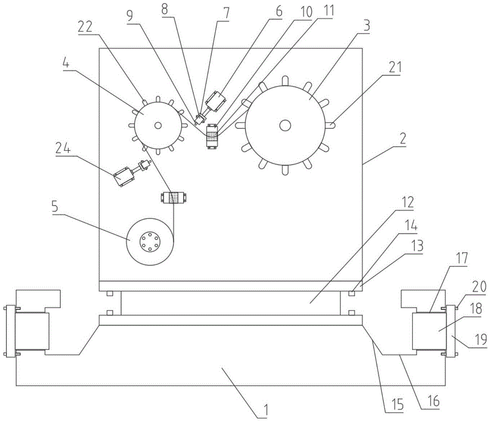
图1为本实用新型一种轻量化羊毛混纺纱用粗纺设备的整体结构示意图。Fig. 1 is a schematic diagram of the overall structure of a roving equipment for lightweight wool blended yarn of the present invention.
图2为本实用新型一种轻量化羊毛混纺纱用粗纺设备的底座俯视结构示意图。Fig. 2 is a structural schematic diagram of a top view of a base of a roving equipment for lightweight wool blended yarn of the present invention.
图3为本实用新型一种轻量化羊毛混纺纱用粗纺设备的底座与卡块拆分后结构示意图。Fig. 3 is a structural schematic diagram of a slubbing equipment for lightweight wool blended yarn of the present invention after disassembly of the base and blocks.
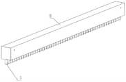
图4为本实用新型一种轻量化羊毛混纺纱用粗纺设备的条形块和梳理齿结构示意图。Fig. 4 is a structural schematic diagram of a strip block and carding teeth of a roving equipment for lightweight wool blended yarn of the present invention.
图5为本实用新型一种轻量化羊毛混纺纱用粗纺设备的驱动电机与第一梳理辊连接结构示意图。Fig. 5 is a schematic diagram of the connection structure between the driving motor and the first carding roller of a roving equipment for lightweight wool blended yarn of the present invention.
图中:1、底座;2、立板;3、第一梳理辊;4、第二梳理辊;5、收卷辊;6、第一伺服电缸;7、U形连接块;8、条形块;9、梳理齿;10、固定圈;11、预留孔;12、支撑板;13、连接盘;14、连接螺钉;15、斜坡面;16、收集槽;17、预留槽;18、卡块;19、限位板;20、锁紧螺钉;21、粗齿;22、细齿;23、驱动电机;24、第二伺服电缸。In the figure: 1. base; 2. vertical plate; 3. first carding roller; 4. second carding roller; 5. winding roller; 6. first servo electric cylinder; 7. U-shaped connecting block; 8. bar Shaped block; 9. Combing teeth; 10. Fixed ring; 11. Reserved hole; 12. Support plate; 13. Connecting disc; 14. Connecting screw; 15. Slope surface; 16. Collecting tank; 17. Reserved tank; 18. Block; 19. Limiting plate; 20. Locking screw; 21. Coarse teeth; 22. Fine teeth; 23. Driving motor; 24. Second servo electric cylinder.
具体实施方式Detailed ways
为使本实用新型实现的技术手段、创作特征、达成目的与功效易于明白了解,下面结合具体实施方式,进一步阐述本实用新型。In order to make the technical means, creative features, goals and effects achieved by the utility model easy to understand, the utility model will be further elaborated below in conjunction with specific embodiments.
如图1和图4所示,一种轻量化羊毛混纺纱用粗纺设备,包括底座1、立板2、第一梳理辊3、第二梳理辊4和收卷辊5,所述第一梳理辊3和第二梳理辊4外围分别设置有粗齿21和细齿22,所述立板2一侧靠近所述第一梳理辊3与第二梳理辊4之间处通过螺钉安装有第一伺服电缸6,所述立板2一侧靠近所述第二梳理辊4下端处通过螺钉安装有第二伺服电缸24,所述第一伺服电缸6和第二伺服电缸24的动力输出端均连接有U形连接块7,所述U形连接块7内侧通过螺钉安装有条形块8,所述条形块8端部设置有梳理齿9。As shown in Fig. 1 and Fig. 4, a kind of roving equipment for lightweight wool blended yarn comprises a base 1, a vertical board 2, a
其中,所述立板2一侧靠近所述第一伺服电缸6下端处、所述立板2一侧靠近所述收卷辊5上端处均通过螺钉安装有固定圈10,所述固定圈10内贯穿开设有预留孔11。Wherein, one side of the vertical plate 2 is close to the lower end of the first servo
本实施例中如图1所示,通过预留孔11,方便对羊毛在移动时进行限位导向。In this embodiment, as shown in FIG. 1 , through the reserved
其中,所述立板2一侧与第一梳理辊3、第二梳理辊4和收卷辊5对应位置均通过安装槽安装有驱动电机23,所述驱动电机23的动力输出端分别对应与第一梳理辊3、第二梳理辊4和收卷辊5连接。Wherein, one side of the vertical plate 2 and the
本实施例中如图1和图5所示,驱动电机23在工作时方便带动第一梳理辊3、第二梳理辊4和收卷辊5进行转动。In this embodiment, as shown in FIG. 1 and FIG. 5 , the driving
其中,所述底座1位于立板2下端,所述底座1与立板2之间设置有支撑板12,所述支撑板12顶部和底部均焊接有连接盘13,两组所述连接盘13分别通过连接螺钉14与立板2和底座1连接。Wherein, the base 1 is located at the lower end of the vertical plate 2, and a
本实施例中如图1所示,通过连接螺钉14,方便对连接盘13与立板2与底座1进行连接,从而方便将支撑板12固定在底座1与立板2之间,通过拆卸连接螺钉14,方便对底座1与立板2之间进行分离。In this embodiment, as shown in Figure 1, the
其中,所述底座1顶部靠近边缘处开设有收集槽16,所述靠近所述收集槽16内边缘处设置有斜坡面15,所述底座1两端均开设有预留槽17,所述预留槽17内设置有卡块18,所述卡块18外侧连接有限位板19,所述限位板19与底座1端部之间通过锁紧螺钉20进行紧固连接。Wherein, the top of the base 1 is provided with a
本实施例中如图1、图2和图3所示,在粗纺中掉落的羊毛纤维经由斜坡面15的导向进入收集槽16内收集,人员通过拧松锁紧螺钉20,方便将卡块18从预留槽17内拆离,进而便于经由预留槽17将收集槽16内的羊毛纤维进行清理。In this embodiment, as shown in Fig. 1, Fig. 2 and Fig. 3, the wool fibers falling in the woolen spinning are collected in the collecting
需要说明的是,本实用新型为一种轻量化羊毛混纺纱用粗纺设备,工作时,驱动电机23在工作时方便带动第一梳理辊3、第二梳理辊4和收卷辊5进行转动,羊毛原料经由第一梳理辊3外围的粗齿21进行初步梳理,再经由第二梳理辊4外围的细齿22进行进一步梳理,最终经由收卷辊5进行绕卷,第一伺服电缸6和第二伺服电缸24在工作时,动力输出端方便带动条形块8和梳理齿9进行移动,利用梳理齿9插入移动的羊毛纤维之间,从而可以进一步对羊毛进行梳理,有利于降低羊毛在粗纺后剩余杂质,在粗纺中掉落的羊毛纤维经由斜坡面15的导向进入收集槽16内收集,人员通过拧松锁紧螺钉20,方便将卡块18从预留槽17内拆离,进而便于经由预留槽17将收集槽16内的羊毛纤维进行清理。It should be noted that the utility model is a roving equipment for lightweight wool blended yarn. When working, the driving
以上显示和描述了本实用新型的基本原理和主要特征和本实用新型的优点。本行业的技术人员应该了解,本实用新型不受上述实施例的限制,上述实施例和说明书中描述的只是说明本实用新型的原理,在不脱离本实用新型精神和范围的前提下,本实用新型还会有各种变化和改进,这些变化和改进都落入要求保护的本实用新型范围内。本实用新型要求保护范围由所附的权利要求书及其等效物界定。The basic principles and main features of the present utility model and the advantages of the present utility model have been shown and described above. Those skilled in the art should understand that the utility model is not limited by the above-mentioned embodiments. The above-mentioned embodiments and descriptions only illustrate the principle of the utility model. Without departing from the spirit and scope of the utility model, the utility model The new model also has various changes and improvements, and these changes and improvements all fall within the scope of the claimed utility model. The scope of protection required by the utility model is defined by the appended claims and their equivalents.
Claims (5)
Priority Applications (1)
| Application Number | Priority Date | Filing Date | Title |
|---|---|---|---|
| CN202221373675.7U CN217809819U (en) | 2022-06-02 | 2022-06-02 | A kind of slubbing equipment for lightweight wool blended yarn |
Applications Claiming Priority (1)
| Application Number | Priority Date | Filing Date | Title |
|---|---|---|---|
| CN202221373675.7U CN217809819U (en) | 2022-06-02 | 2022-06-02 | A kind of slubbing equipment for lightweight wool blended yarn |
Publications (1)
| Publication Number | Publication Date |
|---|---|
| CN217809819U true CN217809819U (en) | 2022-11-15 |
Family
ID=83987474
Family Applications (1)
| Application Number | Title | Priority Date | Filing Date |
|---|---|---|---|
| CN202221373675.7U Expired - Fee Related CN217809819U (en) | 2022-06-02 | 2022-06-02 | A kind of slubbing equipment for lightweight wool blended yarn |
Country Status (1)
| Country | Link |
|---|---|
| CN (1) | CN217809819U (en) |
Cited By (1)
| Publication number | Priority date | Publication date | Assignee | Title |
|---|---|---|---|---|
| CN117845341A (en) * | 2022-11-29 | 2024-04-09 | 于越 | Wool processing method |
-
2022
- 2022-06-02 CN CN202221373675.7U patent/CN217809819U/en not_active Expired - Fee Related
Cited By (1)
| Publication number | Priority date | Publication date | Assignee | Title |
|---|---|---|---|---|
| CN117845341A (en) * | 2022-11-29 | 2024-04-09 | 于越 | Wool processing method |
Similar Documents
| Publication | Publication Date | Title |
|---|---|---|
| CN111733493A (en) | Efficient dust removal method for spinning frame | |
| CN215668330U (en) | Carding machine fibre arrangement recovery unit convenient to it is clean | |
| CN220131593U (en) | Textile fiber anti-winding device for spinning | |
| CN219823238U (en) | Spinning bobbin with dust removal function | |
| CN217616496U (en) | Cleaning device for ring spinning technology weaving | |
| CN216663328U (en) | Cold-proof cotton fibre carding machine convenient to flattening | |
| CN219363902U (en) | Efficient adjustable carding machine for spinning | |
| CN210314642U (en) | Cleaning device for ring spinning machine | |
| CN221544877U (en) | Air spinning cotton yarn production equipment | |
| CN220812769U (en) | Cradle roller cleaning device | |
| CN216514342U (en) | Intelligent automatic fly frame | |
| CN223481372U (en) | Novel air spinning drawing drafting assembly | |
| CN210278636U (en) | Dust removing device for textile machinery | |
| CN220202128U (en) | Spinning machine with cleaning device | |
| CN221663106U (en) | Air-flow spinning impurity removing device | |
| CN217418892U (en) | Fiber treatment system | |
| CN214400854U (en) | Cleaning device for flying wadding on spinning frame | |
| CN216338164U (en) | Compact sirospun spinning frame | |
| CN221663110U (en) | Cotton wool collecting device for weaving machinery | |
| CN219991811U (en) | Fly frame transmission device capable of removing dust for wear-resistant yarns | |
| CN224118484U (en) | Wire arranging device for spinning processing | |
| CN214992055U (en) | An automatic detection and cleaning system for cotton spinning foreign matter | |
| CN222205588U (en) | A carding machine with cotton wool cleaning and collecting function | |
| CN217748575U (en) | Dust shaker that combines dust removal comb and parallel cotton fibers prior to spinning | |
| CN215628896U (en) | A textile dust collection device for a textile machine for blankets |
Legal Events
| Date | Code | Title | Description |
|---|---|---|---|
| GR01 | Patent grant | ||
| GR01 | Patent grant | ||
| CF01 | Termination of patent right due to non-payment of annual fee |
Granted publication date: 20221115 |
|
| CF01 | Termination of patent right due to non-payment of annual fee |