CN217803055U - Connecting plug-in components injection mold - Google Patents
Connecting plug-in components injection mold Download PDFInfo
- Publication number
- CN217803055U CN217803055U CN202222634605.9U CN202222634605U CN217803055U CN 217803055 U CN217803055 U CN 217803055U CN 202222634605 U CN202222634605 U CN 202222634605U CN 217803055 U CN217803055 U CN 217803055U
- Authority
- CN
- China
- Prior art keywords
- mould
- fixedly connected
- annular
- injection mold
- die
- Prior art date
- Legal status (The legal status is an assumption and is not a legal conclusion. Google has not performed a legal analysis and makes no representation as to the accuracy of the status listed.)
- Active
Links
- 238000002347 injection Methods 0.000 title claims abstract description 19
- 239000007924 injection Substances 0.000 title claims abstract description 19
- 239000000872 buffer Substances 0.000 claims abstract description 9
- 238000007493 shaping process Methods 0.000 claims abstract description 6
- 229920003023 plastic Polymers 0.000 abstract description 7
- 239000004033 plastic Substances 0.000 abstract description 7
- 238000000465 moulding Methods 0.000 abstract description 6
- 230000001771 impaired effect Effects 0.000 abstract description 3
- 230000001737 promoting effect Effects 0.000 abstract description 2
- 238000001746 injection moulding Methods 0.000 description 9
- 238000009434 installation Methods 0.000 description 4
- 230000008901 benefit Effects 0.000 description 2
- 230000007246 mechanism Effects 0.000 description 2
- 230000000712 assembly Effects 0.000 description 1
- 238000000429 assembly Methods 0.000 description 1
- 230000007547 defect Effects 0.000 description 1
- 238000006073 displacement reaction Methods 0.000 description 1
- 230000000694 effects Effects 0.000 description 1
- 230000002349 favourable effect Effects 0.000 description 1
- 238000000034 method Methods 0.000 description 1
- 238000012986 modification Methods 0.000 description 1
- 230000004048 modification Effects 0.000 description 1
- 230000008569 process Effects 0.000 description 1
Images


Landscapes
- Moulds For Moulding Plastics Or The Like (AREA)
Abstract
The utility model discloses a connect plug-in components injection mold, comprises an upper die, the below symmetry of going up the mould is equipped with two well moulds, two the below of well mould is equipped with the lower mould, constitute between last mould, well mould and the lower mould and connect plug-in components shaping die cavity, the bottom fixed mounting of lower mould has the ejecting subassembly of annular, the bottom fixed mounting of the ejecting subassembly of annular has the bottom plate, four buffers of the symmetrical fixedly connected with in top of bottom plate, four the equal fixed mounting in top of buffer has the frame, install the promotion subassembly between frame and two well moulds jointly. The utility model discloses in, the mould adopts split type design, accomplishes the back at moulding plastics, opens two well moulds through promoting the subassembly, then ejecting through ejecting subassembly with fashioned connection plug-in components for the drawing of patterns is more simple, avoids causing connection plug-in components surface screw thread impaired, guarantees the outward appearance and the quality of connecting plug-in components.
Description
Technical Field
The utility model relates to an injection mold technical field especially relates to a connect plug-in components injection mold.
Background
In the electrical connection of the data acquisition device, a high-strength connecting plug-in is usually used to electrically connect different elements, wherein the main body of the connecting plug-in is mainly a plastic product and is mainly manufactured through an injection molding process, and an injection mold is the core of the injection molding process of the plastic connecting plug-in;
its surface of connecting plug-in components that present data acquisition ware was used has integrated into one piece's screw, when finishing moulding plastics, needs ejecting and carry out the drawing of patterns with the product, because connecting plug-in components external screw thread is by the mold insert block for the drawing of patterns of external screw thread is comparatively complicated, if takes off by force, causes connecting plug-in components external screw thread impaired easily, leads to influencing product outward appearance and quality.
SUMMERY OF THE UTILITY MODEL
The utility model aims at solving the defects existing in the prior art and providing an injection mold for connecting plug-ins.
In order to achieve the above purpose, the utility model adopts the following technical scheme: the utility model provides a connect plug-in components injection mold, includes the mould, the below symmetry of going up the mould is equipped with two well moulds, two the below of well mould is equipped with the lower mould, constitute between last mould, well mould and the lower mould and connect plug-in components shaping die cavity, the bottom fixed mounting of lower mould has the ejecting subassembly of annular, the bottom fixed mounting of the ejecting subassembly of annular has the bottom plate, four buffers of the symmetrical fixedly connected with in top of bottom plate, four the equal fixed mounting in top of buffer has the frame, install between frame and two well moulds jointly and promote the subassembly.
Further, annular ejecting subassembly includes the mount pad, and fixed connection between mount pad and bottom plate and the lower mould, the interior bottom of mount pad is equipped with the mounting panel, two ejector pins of the symmetrical fixedly connected with in top of mounting panel, two the common fixedly connected with annular kicking block in top of ejector pin, two the surface of ejector pin all overlaps and is equipped with the spring, and fixed connection between spring and mounting panel and the lower mould is favorable to ejecting with the connection plug-in components after the shaping.
Furthermore, the bottom has seted up the ring channel in the die cavity of lower mould, and sliding connection between ring channel and the annular kicking block, two spacing holes have been seted up to the interior bottom symmetry of ring channel, and the ejector pin runs through spacing hole and sliding connection with it, is sliding fit between ring channel and the annular kicking block, avoids taking place the connecting plug-in components bottom after the shaping and appears the overlap.
Further, two the promotion subassembly all includes the hydro-cylinder, and fixed connection between hydro-cylinder and the frame, two the expansion end of hydro-cylinder all with adjacent well mould between fixed connection, the both sides of hydro-cylinder all are equipped with the gag lever post, and between gag lever post and the frame sliding connection and adjacent well mould between fixed connection, the gag lever post has limiting displacement, guarantees well mould and moves steadily under the drive of hydro-cylinder.
Furthermore, go up four second guide posts of bottom fixedly connected with of mould, two the top symmetry of well mould is seted up two and second guide post assorted guiding hole, two the equal symmetrical two third guide posts of fixedly connected with in bottom of well mould, four and third guide post assorted third guide holes are seted up at the top of lower mould, have the direction, avoid when moulding plastics, lower mould, well mould and lower mould position take place the skew.
Furthermore, four first guide posts are symmetrically and fixedly connected to the inner end face of one middle die, and four first guide holes matched with the first guide posts are symmetrically formed in the inner end face of the other middle die, so that a guide effect is achieved, and the position deviation of the two middle dies is avoided during injection molding.
Furthermore, the top fixedly connected with upper fixed plate of going up the mould, upper fixed plate is provided with and does benefit to the mould and is connected with the injection molding machine.
The utility model has the advantages that:
the utility model discloses when using, this connection plug-in components injection mold, mould adopt split type design, after the completion of moulding plastics, open two well moulds through promoting the subassembly, then ejecting through the ejecting subassembly of annular with fashioned connection plug-in components for the drawing of patterns is more simple, avoids causing connection plug-in components surface screw thread impaired, guarantees the outward appearance and the quality of connecting plug-in components.
Drawings
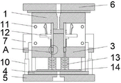
Fig. 1 is a schematic view of the overall structure of the present invention;
fig. 2 is a cross-sectional view of the present invention;
fig. 3 is an enlarged view of a portion a in fig. 2 according to the present invention.
Illustration of the drawings:
1. an upper die; 2. a middle mold; 3. a lower die; 4. a mounting seat; 5. a lower fixing plate; 6. an upper fixing plate; 7. a frame; 8. a limiting rod; 9. an oil cylinder; 10. a buffer; 11. a first guide post; 12. connecting the insert molding die cavity; 13. a spring; 14. mounting a plate; 15. an annular groove; 16. an annular top block; 17. a top rod; 18. and a limiting hole.
Detailed Description
Fig. 1 to fig. 3 show, relate to a connect plug-in components injection mold, including last mould 1, the below symmetry of going up mould 1 is equipped with two well moulds 2, the below of two well moulds 2 is equipped with lower mould 3, go up mould 1, constitute between well mould 2 and the lower mould 3 and connect plug-in components shaping die cavity 12, the bottom fixed mounting of lower mould 3 has the ejecting subassembly of annular, the bottom fixed mounting of the ejecting subassembly of annular has bottom plate 5, four buffers 10 of the symmetrical fixedly connected with in top of bottom plate 5, the equal fixed mounting in top of four buffers 10 has frame 7, install between frame 7 and two well moulds 2 jointly and promote the subassembly.
As shown in fig. 1, the two pushing assemblies each include an oil cylinder 9, the oil cylinders 9 and the frames 7 are fixedly connected, the movable ends of the two oil cylinders 9 are fixedly connected with the adjacent middle molds 2, the two sides of each oil cylinder 9 are provided with a limiting rod 8, and the limiting rods 8 and the frames 7 are slidably connected and fixedly connected with the adjacent middle molds 2.
As shown in fig. 1 and 2, the bottom of the upper die 1 is fixedly connected with four second guide posts, the top of the two middle dies 2 are symmetrically provided with two guide holes matched with the second guide posts, the bottom of the two middle dies 2 are symmetrically and fixedly connected with two third guide posts, and the top of the lower die 3 is provided with four third guide holes matched with the third guide posts.
The inner end face of a single middle die 2 is symmetrically and fixedly connected with four first guide posts 11, and the inner end face of the other middle die 2 is symmetrically provided with four first guide holes matched with the first guide posts 11.
The top of the upper die 1 is fixedly connected with an upper fixing plate 6.
As shown in fig. 2 and 3, the annular ejection assembly comprises a mounting seat 4, the mounting seat 4 is fixedly connected with the lower fixing plate 5 and the lower die 3, a mounting plate 14 is arranged at the inner bottom of the mounting seat 4, two ejector rods 17 are symmetrically and fixedly connected with the top of the mounting plate 14, annular ejector blocks 16 are fixedly connected with the tops of the two ejector rods 17 together, springs 13 are sleeved on the outer surfaces of the two ejector rods 17, and the springs 13 are fixedly connected with the mounting plate 14 and the lower die 3.
As shown in fig. 3, an annular groove 15 is formed in the bottom of the mold cavity of the lower mold 3, the annular groove 15 is slidably connected with an annular top block 16, two limiting holes 18 are symmetrically formed in the bottom of the annular groove 15, and a top rod 17 penetrates through the limiting holes 18 and is slidably connected with the limiting holes 18.
When the connecting plug-in injection mold is used, firstly, the whole connecting plug-in injection mold is installed on an injection molding machine, then, the movable end of an external ejection driving mechanism is fixedly connected with an installation plate 14, during injection molding, an oil cylinder 9 pushes two middle molds 2 to be close to each other until the two middle molds 2 are tightly attached to each other, then, the injection molding machine drives a lower mold 3 to be close to an upper mold 1 until the lower mold 3 and the middle molds 2 are tightly attached to each other, the middle molds 2 are tightly attached to the upper mold 1, then, molten plastics are injected into a connecting plug-in molding mold cavity 12, after the connecting plug-in is molded, the injection molding machine drives a lower fixing plate 5 and an installation seat 4 to be slightly away from the upper mold 1, at the moment, gaps occur between the middle molds 2 and the upper mold 1 and the lower mold 3, then, the injection molding machine drives the lower mold 3 to be away from the upper mold 1, then, the external ejection mechanism drives the installation plate 14 to be close to the lower mold 3, the installation plate 14 drives an ejector rod 17 to move in a limiting hole 18, so as to drive an annular ejector block 16 to move towards one side of the middle molds 2, and the annular ejector block 16 ejects the connecting plug-in moving process.
The above description is only for the preferred embodiment of the present invention, and is not intended to limit the present invention, and any modifications, equivalent replacements, improvements, etc. made within the spirit and principle of the present invention should be included within the protection scope of the present invention.
Claims (7)
1. The utility model provides a connect plug-in components injection mold, includes mould (1), its characterized in that: the below symmetry of going up mould (1) is equipped with two well moulds (2), two the below of well mould (2) is equipped with lower mould (3), go up and constitute between mould (1), well mould (2) and lower mould (3) and connect plug-in components shaping die cavity (12), the bottom fixed mounting of lower mould (3) has the ejecting subassembly of annular, the bottom fixed mounting of the ejecting subassembly of annular has bottom plate (5), four buffers (10) of the top symmetry fixedly connected with of bottom plate (5), four the equal fixed mounting in top of buffer (10) has frame (7), install between frame (7) and two well moulds (2) jointly and promote the subassembly.
2. A connection insert injection mold according to claim 1, wherein: the ejecting subassembly of annular includes mount pad (4), and fixed connection between mount pad (4) and bottom plate (5) and lower mould (3), the interior bottom of mount pad (4) is equipped with mounting panel (14), two ejector pins (17) of the top symmetry fixedly connected with of mounting panel (14), two the common fixedly connected with annular kicking block (16) in top of ejector pin (17), two the surface of ejector pin (17) all overlaps and is equipped with spring (13), and fixed connection between spring (13) and mounting panel (14) and lower mould (3).
3. A connection insert injection mold according to claim 2, wherein: the die comprises a lower die (3) and is characterized in that an annular groove (15) is formed in the bottom of a die cavity of the lower die (3), the annular groove (15) is connected with an annular top block (16) in a sliding mode, two limiting holes (18) are symmetrically formed in the bottom of the annular groove (15), and a top rod (17) penetrates through the limiting holes (18) and is connected with the limiting holes in a sliding mode.
4. A connection insert injection mold according to claim 1, wherein: two the promotion subassembly all includes hydro-cylinder (9), and fixed connection between hydro-cylinder (9) and frame (7), two the expansion end of hydro-cylinder (9) all with adjacent well mould (2) between fixed connection, the both sides of hydro-cylinder (9) all are equipped with gag lever post (8), and between gag lever post (8) and frame (7) sliding connection and with adjacent well mould (2) between fixed connection.
5. A connecting insert injection mold according to claim 1, wherein: the bottom of the upper die (1) is fixedly connected with four second guide posts, the top of the middle die (2) is symmetrically provided with two guide holes matched with the second guide posts, the bottom of the middle die (2) is symmetrically and fixedly connected with two third guide posts, and the top of the lower die (3) is provided with four third guide holes matched with the third guide posts.
6. A connection insert injection mold according to claim 1, wherein: four first guide posts (11) are symmetrically and fixedly connected to the inner end face of one middle die (2), and four first guide holes matched with the first guide posts (11) are symmetrically formed in the inner end face of the other middle die (2).
7. A connection insert injection mold according to claim 1, wherein: the top of the upper die (1) is fixedly connected with an upper fixing plate (6).
Priority Applications (1)
| Application Number | Priority Date | Filing Date | Title |
|---|---|---|---|
| CN202222634605.9U CN217803055U (en) | 2022-10-09 | 2022-10-09 | Connecting plug-in components injection mold |
Applications Claiming Priority (1)
| Application Number | Priority Date | Filing Date | Title |
|---|---|---|---|
| CN202222634605.9U CN217803055U (en) | 2022-10-09 | 2022-10-09 | Connecting plug-in components injection mold |
Publications (1)
| Publication Number | Publication Date |
|---|---|
| CN217803055U true CN217803055U (en) | 2022-11-15 |
Family
ID=83977278
Family Applications (1)
| Application Number | Title | Priority Date | Filing Date |
|---|---|---|---|
| CN202222634605.9U Active CN217803055U (en) | 2022-10-09 | 2022-10-09 | Connecting plug-in components injection mold |
Country Status (1)
| Country | Link |
|---|---|
| CN (1) | CN217803055U (en) |
Cited By (1)
| Publication number | Priority date | Publication date | Assignee | Title |
|---|---|---|---|---|
| CN120134553A (en) * | 2025-05-15 | 2025-06-13 | 泉州远锦新材料科技有限公司 | A kind of sole injection mold for shoe making |
-
2022
- 2022-10-09 CN CN202222634605.9U patent/CN217803055U/en active Active
Cited By (2)
| Publication number | Priority date | Publication date | Assignee | Title |
|---|---|---|---|---|
| CN120134553A (en) * | 2025-05-15 | 2025-06-13 | 泉州远锦新材料科技有限公司 | A kind of sole injection mold for shoe making |
| CN120134553B (en) * | 2025-05-15 | 2025-07-29 | 泉州远锦新材料科技有限公司 | Sole injecting glue mould for shoemaking |
Similar Documents
| Publication | Publication Date | Title |
|---|---|---|
| CN219786514U (en) | Bicycle part die casting die convenient to drawing of patterns | |
| CN212736907U (en) | Injection mold | |
| CN110193916B (en) | Double-inclined-top structure of injection mold for automobile back door | |
| CN221417299U (en) | Massage instrument shell mould | |
| CN221437121U (en) | Four-side demoulding mechanism of clamping plate box injection mould | |
| CN220331884U (en) | Stroke control structure of soft rubber secondary ejection die | |
| CN218366270U (en) | Injection mold capable of realizing rapid demolding | |
| CN215203255U (en) | Lateral core-pulling limiting mold opening structure | |
| CN217803133U (en) | Rotary ejection mechanism of injection mold | |
| CN216708220U (en) | Forming die of multichannel valve body | |
| CN216579031U (en) | Eccentric injection mold is prevented to slender core | |
| CN217373094U (en) | Secondary loose core mould device | |
| CN216032182U (en) | Injection mold for notebook computer antenna production | |
| CN215039886U (en) | Children's ladder toilet bowl body injection mould based on hydro-cylinder side drawing of core drawing die technique | |
| CN212979085U (en) | Glasses leg injection mold | |
| CN209903838U (en) | Ejector sleeve ejecting mechanism with limited space | |
| CN210047005U (en) | Structure for converting diagonal line position into horizontal line position | |
| CN218111585U (en) | Forming die of buckle seal | |
| CN220314044U (en) | Secondary ejector block demoulding mechanism of automobile instrument panel body mould | |
| CN222832295U (en) | Straight ejector block core pulling mechanism of automobile headlamp decorative frame mold | |
| CN222645248U (en) | Composite inclined lift mechanism for dual-color headlamp mirror mold | |
| CN223369925U (en) | 250A high-current inner core injection mold | |
| CN220864668U (en) | Delayed guide plate core-pulling demoulding mechanism of automobile interior trim part mould | |
| CN219076392U (en) | Silica gel finger stall injection mold | |
| CN219256361U (en) | Forming die of automobile water film support |
Legal Events
| Date | Code | Title | Description |
|---|---|---|---|
| GR01 | Patent grant | ||
| GR01 | Patent grant |