CN217800274U - Simple clamp for fixing unclamping arm - Google Patents
Simple clamp for fixing unclamping arm Download PDFInfo
- Publication number
- CN217800274U CN217800274U CN202220834715.7U CN202220834715U CN217800274U CN 217800274 U CN217800274 U CN 217800274U CN 202220834715 U CN202220834715 U CN 202220834715U CN 217800274 U CN217800274 U CN 217800274U
- Authority
- CN
- China
- Prior art keywords
- arm
- supporting column
- mounting hole
- knife
- branch dagger
- Prior art date
- Legal status (The legal status is an assumption and is not a legal conclusion. Google has not performed a legal analysis and makes no representation as to the accuracy of the status listed.)
- Active
Links
- 238000010009 beating Methods 0.000 claims abstract description 14
- 238000005242 forging Methods 0.000 claims description 18
- 238000010030 laminating Methods 0.000 claims description 5
- 238000003754 machining Methods 0.000 abstract description 6
- 238000002360 preparation method Methods 0.000 abstract description 2
- 238000009434 installation Methods 0.000 description 2
- 238000000034 method Methods 0.000 description 2
- 238000003825 pressing Methods 0.000 description 2
- 206010066054 Dysmorphism Diseases 0.000 description 1
- 230000004075 alteration Effects 0.000 description 1
- 230000009286 beneficial effect Effects 0.000 description 1
- 238000010586 diagram Methods 0.000 description 1
- 238000005516 engineering process Methods 0.000 description 1
- 238000004880 explosion Methods 0.000 description 1
- 230000014509 gene expression Effects 0.000 description 1
- 238000012986 modification Methods 0.000 description 1
- 230000004048 modification Effects 0.000 description 1
- 238000004904 shortening Methods 0.000 description 1
- 238000006467 substitution reaction Methods 0.000 description 1
- 238000003466 welding Methods 0.000 description 1
Images

Landscapes
- Forging (AREA)
Abstract
The utility model relates to the technical field of machining, in particular to a simple clamp for fixing a cutter arm, which comprises a cutter arm, a left support column and a right support column, wherein the cutter arm is arranged at the upper sides of the left support column and the right support column; a first mounting hole is formed in one end of the top side of the front end face of the left supporting column, the first mounting hole and the round hole in the left side of the unclamping arm are coaxially arranged, a second mounting hole is formed in the top side of the front end face of the right supporting column, and the second mounting hole and the round hole in the right side of the unclamping arm are coaxially arranged; the top end surface of the cutter beating arm is parallel to the top end surface of the bottom plate; a clamping groove is formed in the front side of the left supporting column, the clamping groove is arranged in a triangular prism shape, and the inner side of the clamping groove is attached to the rear side of the unclamping arm; the utility model discloses in, not only structural design is reasonable, and the preparation is convenient simple, and simple to operate is quick moreover, and is fixed more reliable and more stable.
Description
Technical Field
The utility model relates to a machinery processing technology field specifically is a simple and easy anchor clamps of fixed arm of forging a knife.
Background
The numerical control machine tool is an automatic device which can finish various machining processes by clamping a workpiece once and replace different cutters according to different machining requirements. A tool beating arm in a numerical control machine tool is a tool for assisting a machine tool spindle and a tool magazine to realize automatic tool changing, and the tool beating arm is an important part for improving the machining efficiency of the machine tool, reducing the labor cost and shortening the machining time; the tool arm is put on a machine tool for processing, the existing fixing scheme is that an inclined backing plate is used for backing the lower part of the tool arm, and then a pressing plate is used for pressing and fixing the tool arm.
SUMMERY OF THE UTILITY MODEL
An object of the utility model is to provide a simple and easy anchor clamps of fixed arm of forging a knife to solve the fixed unstability of arm of forging a knife, problem that machining precision is low.
In order to achieve the above object, the utility model provides a following technical scheme:
the utility model provides a simple and easy anchor clamps of fixed arm of forging a knife, includes arm of forging a knife, left branch dagger and right branch dagger, the upside at left branch dagger and right branch dagger is installed to the arm of forging a knife, the bottom plate is installed to the bottom of left branch dagger and right branch dagger, the top of left branch dagger and right branch dagger with the arm of forging a knife laminating.
Preferably, first mounting hole has been seted up to the preceding terminal surface top side one end of left branch dagger, and first mounting hole is with the axle center setting with the left round hole of arm of beating the sword, the second mounting hole has been seted up to the preceding terminal surface top side of right branch dagger, and the second mounting hole is with the axle center setting with the round hole on arm of beating the sword right side.
Preferably, the top end surface of the knife striking arm is parallel to the top end surface of the bottom plate.
Preferably, the front side of left branch dagger is opened and is equipped with the draw-in groove, the draw-in groove is the triangular prism form setting, the inboard of draw-in groove and the rear side laminating of arm of forging a knife.
Preferably, one side of the left support column, which is close to the right support column, is provided with a groove, the groove is arranged in a cylindrical shape, and the groove is attached to the unclamping arm.
Compared with the prior art, the beneficial effects of the utility model are that:
the utility model discloses in, not only structural design is reasonable, and the preparation is convenient simple, and simple to operate is quick moreover, and is fixed more reliable and more stable.
Drawings
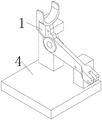
FIG. 1 is a schematic view of the overall structure of the present invention;
fig. 2 is an explosion diagram of the present invention.
In the figure: 1. a cutter beating arm; 2. a left support column; 3. a right support column; 4. a base plate; 5. a first mounting hole; 6. a second mounting hole; 7. a card slot; 8. and (4) a groove.
Detailed Description
The technical solutions in the embodiments of the present invention will be described clearly and completely with reference to the drawings in the embodiments of the present invention, and it is obvious that the described embodiments are only some embodiments of the present invention, not all embodiments. Based on the embodiments in the present invention, all other embodiments obtained by a person skilled in the art without creative work belong to the protection scope of the present invention.
It is noted that the terminology used herein is for the purpose of describing particular embodiments only and is not intended to be limiting of example embodiments according to the present application. As used herein, the singular forms "a", "an" and "the" are intended to include the plural forms as well, and it should be understood that when the terms "comprises" and/or "comprising" are used in this specification, they specify the presence of stated features, steps, operations, devices, components, and/or combinations thereof, unless the context clearly indicates otherwise.
The relative arrangement of the components and steps, the numerical expressions and numerical values set forth in these embodiments do not limit the scope of the present invention unless it is specifically stated otherwise. Meanwhile, it should be understood that the sizes of the respective portions shown in the drawings are not drawn in an actual proportional relationship for the convenience of description. Techniques, methods, and apparatus known to those of ordinary skill in the relevant art may not be discussed in detail but are intended to be part of the specification where appropriate. In all examples shown and discussed herein, any particular value should be construed as exemplary only and not as limiting. Thus, other examples of the exemplary embodiments may have different values. It should be noted that: like reference numbers and letters refer to like items in the following figures, and thus, once an item is defined in one figure, further discussion thereof is not required in subsequent figures.
In the description of the present invention, it is to be understood that the orientation or positional relationship indicated by the orientation words such as "front, rear, upper, lower, left, right", "lateral, vertical, horizontal" and "top, bottom", etc. are usually based on the orientation or positional relationship shown in the drawings, and are only for convenience of description and simplicity of description, and in the case of not making a reverse description, these orientation words do not indicate and imply that the device or element being referred to must have a specific orientation or be constructed and operated in a specific orientation, and therefore, should not be considered as limiting the scope of the present invention; the terms "inner and outer" refer to the inner and outer relative to the profile of the respective component itself.
For ease of description, spatially relative terms such as "over 8230," "upper surface," "above," and the like may be used herein to describe the spatial positional relationship of one device or feature to other devices or features as illustrated in the figures. It will be understood that the spatially relative terms are intended to encompass different orientations of the device in use or operation in addition to the orientation depicted in the figures. For example, if a device in the figures is turned over, devices described as "above" or "on" other devices or configurations would then be oriented "below" or "under" the other devices or configurations. Thus, the exemplary terms "at 8230; \8230; above" may include both orientations "at 8230; \8230; above" and "at 8230; \8230; below". The device may be otherwise variously oriented (rotated 90 degrees or at other orientations) and the spatially relative descriptors used herein interpreted accordingly.
It should be noted that the terms "first", "second", and the like are used to define the components, and are only used for convenience of distinguishing the corresponding components, and the terms have no special meanings unless otherwise stated, and therefore, the scope of the present invention should not be construed as being limited.
Referring to fig. 1-2, the present invention provides a technical solution:
the utility model provides a simple and easy anchor clamps of fixed arm of forging a knife, includes arm of forging a knife 1, left branch dagger 2 and right branch dagger 3, and arm of forging a knife 1 installs the upside at left branch dagger 2 and right branch dagger 3, and bottom plate 4 is installed to the bottom of left branch dagger 2 and right branch dagger 3, the top of left branch dagger 2 and right branch dagger 3 and the laminating of arm of forging a knife 1.
A first mounting hole 5 is formed in one end of the top side of the front end face of the left support column 2, the first mounting hole 5 and a round hole in the left side of the unclamping arm 1 are coaxially arranged, a second mounting hole 6 is formed in the top side of the front end face of the right support column 3, the second mounting hole 6 and a round hole in the right side of the unclamping arm 1 are coaxially arranged, and the arrangement facilitates better fixing treatment of the unclamping arm 1; the top end surface of the unclamping arm 1 is arranged in parallel with the top end surface of the bottom plate 4, and the arrangement ensures the stable and accurate installation of the unclamping arm 1, thereby facilitating the subsequent processing and use; the draw-in groove 7 has been opened to the front side of left branch dagger 2, and draw-in groove 7 is the setting of triangular prism form, and draw-in groove 7's inboard is laminated with the rear side of arm of forging a knife 1, and left branch dagger 2 is close to one side of right branch dagger 3 and sets up fluted 8, and recess 8 is cylindric setting, and recess 8 and the laminating of arm of forging a knife 1, and the rib and the boss to arm of forging a knife 1 that this kind of setting can be better are placed to the problem of installation interference has been avoided.
Those not described in detail in this specification are well within the skill of the art. The utility model discloses the standard part that uses all can purchase from the market, and dysmorphism piece all can be customized according to the description with the record of drawing of description, and the concrete connection mode of each part all adopts conventional means such as ripe bolt, rivet, welding among the prior art, and machinery, part and equipment all adopt prior art, and conventional model, including circuit connection adopts conventional connection mode among the prior art, does not detailed here again.
The working principle is as follows: the device is when using, at first places the upside of the left branch dagger 2 and the right branch dagger 3 of 4 upsides on bottom plates with beating cutter arm 1, then fixes beating cutter arm 1 through round pin axle, first mounting hole 5 and second mounting hole 6, and draw-in groove 7 and recess 8's setting both can avoid beating cutter arm 1 to interfere with left branch dagger 2, right branch dagger 3 when placing, also can strengthen the stability that beating cutter arm 1 placed.
Although embodiments of the present invention have been shown and described, it will be appreciated by those skilled in the art that changes, modifications, substitutions and alterations can be made in these embodiments without departing from the principles and spirit of the invention, the scope of which is defined in the appended claims and their equivalents.
Claims (4)
1. The utility model provides a simple and easy anchor clamps of fixed arm of forging a knife, includes arm of forging a knife (1), left branch dagger (2) and right branch dagger (3), its characterized in that: the knife beating arm (1) is arranged on the upper sides of the left supporting column (2) and the right supporting column (3), the bottom ends of the left supporting column (2) and the right supporting column (3) are provided with bottom plates (4), and the top ends of the left supporting column (2) and the right supporting column (3) are attached to the knife beating arm (1);
first mounting hole (5) have been seted up to the preceding terminal surface top side one end of left branch dagger (2), and first mounting hole (5) are with the axle center setting with the left round hole of arm of beating sword (1), second mounting hole (6) have been seted up to the preceding terminal surface top side of right branch dagger (3), and second mounting hole (6) are with the axle center setting with the round hole on arm of beating sword (1) right side.
2. The simple clamp for fixing the unclamping arm as claimed in claim 1, wherein: the top end surface of the knife striking arm (1) is parallel to the top end surface of the bottom plate (4).
3. The simple clamp for fixing the unclamping arm as claimed in claim 1, wherein: draw-in groove (7) have been opened to the front side of left branch dagger (2), draw-in groove (7) are triangular prism shape and set up, the inboard of draw-in groove (7) and the rear side laminating of arm of forging a knife (1).
4. The simple clamp for fixing the unclamping arm as claimed in claim 1, wherein: one side of the left supporting column (2) close to the right supporting column (3) is provided with a groove (8), the groove (8) is in a cylindrical shape, and the groove (8) is attached to the unclamping arm (1).
Priority Applications (1)
| Application Number | Priority Date | Filing Date | Title |
|---|---|---|---|
| CN202220834715.7U CN217800274U (en) | 2022-04-12 | 2022-04-12 | Simple clamp for fixing unclamping arm |
Applications Claiming Priority (1)
| Application Number | Priority Date | Filing Date | Title |
|---|---|---|---|
| CN202220834715.7U CN217800274U (en) | 2022-04-12 | 2022-04-12 | Simple clamp for fixing unclamping arm |
Publications (1)
| Publication Number | Publication Date |
|---|---|
| CN217800274U true CN217800274U (en) | 2022-11-15 |
Family
ID=83979364
Family Applications (1)
| Application Number | Title | Priority Date | Filing Date |
|---|---|---|---|
| CN202220834715.7U Active CN217800274U (en) | 2022-04-12 | 2022-04-12 | Simple clamp for fixing unclamping arm |
Country Status (1)
| Country | Link |
|---|---|
| CN (1) | CN217800274U (en) |
-
2022
- 2022-04-12 CN CN202220834715.7U patent/CN217800274U/en active Active
Similar Documents
| Publication | Publication Date | Title |
|---|---|---|
| CN201168885Y (en) | Rapid screw compressing apparatus | |
| CN202571920U (en) | Dual-face drilling clamp | |
| CN201815885U (en) | Ejector pin positioning clamp | |
| CN102528503A (en) | Double-sided drilling fixture | |
| CN212822960U (en) | Slant milling flutes frock | |
| CN216990877U (en) | Clamp for machining center with high clamping efficiency and stable clamping stability for special-shaped shell workpiece | |
| CN201744878U (en) | Fixture for fixing wood block | |
| CN205798519U (en) | Drilling on inclined surface positioning tool | |
| CN201735921U (en) | Position hole jig for slow-feeding wire-cutting | |
| CN212705614U (en) | Frame anchor clamps behind battery case | |
| CN211361406U (en) | Clamping device | |
| CN211362629U (en) | Wood processing device | |
| CN216990902U (en) | Special tool for four-axis machining of cam box | |
| CN217776325U (en) | Special tool clamp for machining 24 cutter heads | |
| CN202271209U (en) | Pitched roof processing fixture | |
| CN217044718U (en) | Tooling for processing inclined hole | |
| CN223617228U (en) | Cushion block for processing tensile sample by vertical milling machine | |
| CN220839046U (en) | Clamp for long cylindrical parts | |
| CN217453035U (en) | Special tool for horizontally processing Z-axis slide plate semi-finished product | |
| CN214352279U (en) | Detection tool for automobile workpiece | |
| CN218533621U (en) | Multi-angle positioning clamping processing tool suitable for triaxial processing equipment | |
| CN223394375U (en) | Impeller milling clamp | |
| CN217096174U (en) | Base structure of cnc engraving and milling machine | |
| CN220993798U (en) | Test piece for machine tool precision inspection | |
| CN216326106U (en) | Hoisting equipment buffering accessory material anchor clamps |
Legal Events
| Date | Code | Title | Description |
|---|---|---|---|
| GR01 | Patent grant | ||
| GR01 | Patent grant |