CN217778120U - A printing mechanism flip structure for positive and negative printing - Google Patents
A printing mechanism flip structure for positive and negative printing Download PDFInfo
- Publication number
- CN217778120U CN217778120U CN202222068126.5U CN202222068126U CN217778120U CN 217778120 U CN217778120 U CN 217778120U CN 202222068126 U CN202222068126 U CN 202222068126U CN 217778120 U CN217778120 U CN 217778120U
- Authority
- CN
- China
- Prior art keywords
- printing
- fixedly provided
- workbench
- fixedly arranged
- rotating
- Prior art date
- Legal status (The legal status is an assumption and is not a legal conclusion. Google has not performed a legal analysis and makes no representation as to the accuracy of the status listed.)
- Expired - Fee Related
Links
Images


Landscapes
- Screen Printers (AREA)
Abstract
本实用新型涉及印刷机技术领域,公开了一种用于正反面印刷的印刷机构翻转结构,包括底座,所述底座顶端两侧均固定设置有支撑板,所述底座顶端靠近两个支撑板的一侧固定设置有工作台,所述底座顶端两侧靠近工作台远离两个支撑板的一侧均固定设置有支撑柱,两个所述支撑柱之间固定设置有挡板。本实用新型一种用于正反面印刷的印刷机构翻转结构中,在本印刷机上设置了一个主动滚轮和两个从动滚轮,纸张从工作台传出,进入主动滚轮后由两个从动滚轮滚动进行翻转后再次传入工作台进行再次印刷,结构印刷效果更好,减少了不必要的消耗,在印刷机支撑板内部设置的转动电机可以将需要印刷的物品滚动传入工作台,实现了印刷自动化。

The utility model relates to the technical field of printing machines, and discloses a printing mechanism flip structure for front and back printing. A workbench is fixedly arranged on one side, support columns are fixedly arranged on both sides of the top of the base near the worktable and away from the two support plates, and a baffle is fixedly arranged between the two support columns. In the utility model, a printing mechanism flip structure used for front and back printing, a driving roller and two driven rollers are set on the printing machine, the paper passes out from the workbench, and after entering the driving roller, the two driven rollers After rolling and flipping, it is transferred to the workbench for printing again. The structural printing effect is better and unnecessary consumption is reduced. The rotating motor installed inside the support plate of the printing machine can roll the items to be printed into the workbench, realizing the Printing automation.
Description
技术领域technical field
本实用新型涉及印刷机技术领域,尤其涉及一种用于正反面印刷的印刷机构翻转结构。The utility model relates to the technical field of printing machines, in particular to an inverting structure of a printing mechanism for front and back printing.
背景技术Background technique
印刷文字和图像的机器。现代印刷机一般由装版、涂墨、压印、输纸(包括折叠)等机构组成。它的工作原理是:先将要印刷的文字和图像制成印版,装在印刷机上,然后由人工或印刷机把墨涂敷于印版上有文字和图像的地方,再直接或间接地转印到纸或其他承印物(如纺织品、金属板、塑胶、皮革、木板、玻璃和陶瓷)上,从而复制出与印版相同的印刷品。印刷机的发明和发展,对于人类文明和文化的传播具有重要作用。在对纸张打印完成后,往往需要人工手动对纸张进行翻面,然后才能对纸张的反面进行打印,从而降低了打印的效率,为此,提出一种可自动翻转双面印刷机。A machine for printing text and images. Modern printing machines are generally composed of plate loading, ink application, embossing, paper feeding (including folding) and other mechanisms. Its working principle is: first make the printing plate of the text and image to be printed, install it on the printing machine, and then apply the ink to the place where the text and image are on the printing plate manually or by the printing machine, and then transfer it directly or indirectly Print onto paper or other substrates such as textiles, sheet metal, plastic, leather, wood, glass, and ceramics to reproduce the same print as the printing plate. The invention and development of the printing press played an important role in the spread of human civilization and culture. After the paper is printed, it is often necessary to manually turn the paper over before printing on the reverse side of the paper, thereby reducing the printing efficiency. Therefore, a double-sided printing machine that can automatically turn over is proposed.
经检索,现有专利(公开号为:CN204054906U)公开了一种新型印刷机。该专利技术虽然这种新型印刷机不需根据所生产产品的型号制定对应的印刷滚筒,也无需跟换印刷滚筒,且可控制图文印刷的位置,但是存在不能够双面印刷,不够节省的问题,从而导致工作效率过低。因此,本领域技术人员提供了一种用于正反面印刷的印刷机构翻转结构,以解决上述背景技术中提出的问题。After retrieval, the existing patent (publication number is: CN204054906U) discloses a novel printing machine. Although this new type of printing machine does not need to make a corresponding printing cylinder according to the model of the product produced, it does not need to change the printing cylinder, and it can control the position of graphic printing, but it cannot print on both sides and is not economical enough. problems, resulting in low work efficiency. Therefore, those skilled in the art provide a printing mechanism reversal structure for front and back printing to solve the problems raised in the above-mentioned background technology.
实用新型内容Utility model content
本实用新型的目的是为了解决现有技术中存在的缺点,而提出的一种用于正反面印刷的印刷机构翻转结构,在本印刷机上设置了一个主动滚轮和两个从动滚轮,纸张从工作台传出,进入主动滚轮后由两个从动滚轮滚动进行翻转后再次传入工作台进行再次印刷,结构简单、生产成本低;正反面自动印刷,印刷效果更好,减少了不必要的消耗,在工作台内部设置的两个液压气泵可以带动两个液压伸缩杆将推板向上推动至贴合的部位,让墨盒更加精准的对准需要印刷的物品上,使本印刷机的工作效率逐渐变高。The purpose of this utility model is to solve the shortcomings in the prior art, and propose a printing mechanism flip structure for front and back printing. A driving roller and two driven rollers are set on the printing machine, and the paper is moved from The workbench comes out, and after entering the active roller, it is turned over by two driven rollers, and then it is sent to the workbench for reprinting. The structure is simple and the production cost is low; the front and back are automatically printed, the printing effect is better, and unnecessary printing is reduced. Consumption, the two hydraulic air pumps set inside the workbench can drive two hydraulic telescopic rods to push the push plate up to the fitting position, so that the ink cartridge can be more accurately aligned on the item to be printed, and the working efficiency of the printing machine can be improved. Gradually get higher.
为实现上述目的,本实用新型提供了如下技术方案:一种用于正反面印刷的印刷机构翻转结构,包括底座,所述底座顶端两侧均固定设置有支撑板,所述底座顶端靠近两个支撑板的一侧固定设置有工作台,所述底座顶端两侧靠近工作台远离两个支撑板的一侧均固定设置有支撑柱,两个所述支撑柱远离工作台2的一侧之间固定设置有挡板,所述支撑板内部固定设置有转动电机,所述转动电机输出端固定设置有转动轴,所述转动轴固定设置有转动滚轮,两个所述支撑板远离转动电机一侧固定设置有第一固定螺栓,两个所述支撑板两侧壁靠近转动滚轮均固定设置有固定块,两个所述固定块固定设置有固定板,两个所述支撑柱内部顶端固定设置有主动转动电机,所述主动转动电机输出端固定设置有主动转轴,所述主动转轴固定设置有主动滚轮,两个所述支撑柱远离主动转动电机的一侧固定设置有第二固定螺栓,两个所述支撑柱内部靠近主动转动电机的底端固定设置有两个从动转动电机,两个所述从动转动电机输出端均固定设置有从动转轴,两个所述从动转轴均固定设置有从动滚轮,两个所述支撑柱靠近第二固定螺栓的底端固定设置两个第三固定螺栓;In order to achieve the above purpose, the utility model provides the following technical solutions: a printing mechanism flip structure for front and back printing, including a base, the two sides of the top of the base are fixedly provided with support plates, and the top of the base is close to two One side of the support plate is fixedly provided with a workbench, and both sides of the top of the base are fixedly provided with support columns on the side close to the workbench away from the two support plates, and between the sides of the two support columns away from the workbench 2 A baffle is fixedly installed, a rotating motor is fixedly installed inside the supporting plate, a rotating shaft is fixedly installed at the output end of the rotating motor, and a rotating roller is fixedly installed on the rotating shaft, and the two supporting plates are away from the side of the rotating motor The first fixing bolts are fixedly arranged, the two side walls of the support plates are fixedly arranged with fixed blocks close to the rotating rollers, the two fixed blocks are fixedly arranged with fixed plates, and the inner top ends of the two support columns are fixedly arranged with The active rotation motor, the output end of the active rotation motor is fixedly provided with the active rotating shaft, the active rotating shaft is fixedly provided with the active roller, and the side of the two support columns away from the active rotating motor is fixedly provided with the second fixing bolt, two Two driven rotating motors are fixedly arranged inside the supporting column close to the bottom end of the active rotating motor, and the output ends of the two driven rotating motors are fixedly provided with driven rotating shafts, and the two driven rotating shafts are fixedly arranged There are driven rollers, and two third fixing bolts are fixedly arranged on the bottom ends of the two support columns close to the second fixing bolts;
通过上述技术方案,在本印刷机上设置了一个主动滚轮和两个从动滚轮,纸张从工作台传出,进入主动滚轮后由两个从动滚轮滚动进行翻转后再次传入工作台进行再次印刷,结构简单、生产成本低;正反面自动印刷,印刷效果更好,减少了不必要的消耗。Through the above technical scheme, a driving roller and two driven rollers are installed on this printing machine, the paper is passed out from the workbench, and after entering the driving roller, it is turned over by the two driven rollers and then sent to the workbench for printing again , simple structure, low production cost; automatic printing on the front and back sides, better printing effect, reducing unnecessary consumption.
进一步地,所述底座前端面固定设置有控制台;Further, a console is fixedly arranged on the front end of the base;
通过上述技术方案,工作人员通过控制台来控制机器。Through the above technical solution, the staff controls the machine through the console.
进一步地,所述工作台顶端固定设置有顶板,所述顶板内部固定设置有气缸;Further, a top plate is fixedly arranged on the top of the workbench, and a cylinder is fixedly arranged inside the top plate;
通过上述技术方案,顶板内部的气缸可以带动墨盒。Through the above technical proposal, the cylinder inside the top plate can drive the ink cartridge.
进一步地,所述气缸输出端固定设置有墨盒,所述墨盒底端固定设置有喷嘴;Further, an ink cartridge is fixedly arranged at the output end of the cylinder, and a nozzle is fixedly arranged at the bottom end of the ink cartridge;
通过上述技术方案,墨盒可以通过喷嘴将墨汁喷出。Through the above technical solution, the ink cartridge can eject ink through the nozzle.
进一步地,所述工作台内部固定设置有两个液压气泵;Further, two hydraulic air pumps are fixed inside the workbench;
通过上述技术方案,两个液压气泵带动液压伸缩柱。Through the above technical scheme, two hydraulic air pumps drive the hydraulic telescopic column.
进一步地,两个所述液压气泵输出端均固定设置有液压伸缩柱;Further, the output ends of the two hydraulic air pumps are fixedly provided with hydraulic telescopic columns;
通过上述技术方案,液压伸缩柱可以将推板向上推起。Through the above technical solution, the hydraulic telescopic column can push up the push plate.
进一步地,所述工作台内部两侧均固定设置有滑杆,两个所述滑杆均固定设置有滑块;Further, both sides of the workbench are fixedly provided with sliding bars, and both of the two sliding bars are fixedly provided with sliders;
通过上述技术方案,滑块通过滑杆上下滑动。Through the above technical solution, the slide block slides up and down through the slide bar.
进一步地,两个所述滑块上滑动设置有推板;Further, push plates are slidingly arranged on the two sliders;
通过上述技术方案,推板上可以放置需要印刷的物品。Through the above technical solution, items to be printed can be placed on the push plate.
本实用新型具有如下有益效果:The utility model has the following beneficial effects:
1、本实用新型提出的一种用于正反面印刷的印刷机构翻转结构,在本印刷机上设置了一个主动滚轮和两个从动滚轮,纸张从工作台传出,进入主动滚轮后由两个从动滚轮滚动进行翻转后再次传入工作台进行再次印刷,结构简单、生产成本低;正反面自动印刷,印刷效果更好,减少了不必要的消耗。1. The utility model proposes a printing mechanism flip structure for front and back printing. One driving roller and two driven rollers are set on the printing machine. The paper passes out from the workbench and enters the driving roller. The driven roller rolls to turn over and then transfers to the workbench for re-printing. The structure is simple and the production cost is low; the front and back sides are automatically printed, the printing effect is better, and unnecessary consumption is reduced.
2、本实用新型提出的一种用于正反面印刷的印刷机构翻转结构,在工作台内部设置的两个液压气泵可以带动两个液压伸缩杆将推板向上推动至贴合的部位,让墨盒更加精准的对准需要印刷的物品上,使本印刷机的工作效率逐渐变高。2. The utility model proposes a printing mechanism flip structure for front and back printing. Two hydraulic air pumps installed inside the workbench can drive two hydraulic telescopic rods to push the push plate upward to the joint position, allowing the ink cartridge More accurate alignment on the items to be printed will gradually increase the working efficiency of this printing machine.
3、本实用新型提出的一种用于正反面印刷的印刷机构翻转结构,在印刷机支撑板内部设置的转动电机可以将需要印刷的物品滚动传入工作台,实现了印刷自动化,同时也减轻了工作人员的负担。3. The utility model proposes a printing mechanism flip structure for front and back printing. The rotating motor installed inside the support plate of the printing machine can roll the items to be printed into the workbench, realizing printing automation and reducing the burden on the staff.
附图说明Description of drawings
图1为本实用新型提出的一种用于正反面印刷的印刷机构翻转结构的轴测图;Fig. 1 is an axonometric view of a printing mechanism flip structure for front and back printing proposed by the utility model;
图2为本实用新型提出的一种用于正反面印刷的印刷机构翻转结构的支撑板俯剖图;Fig. 2 is a top sectional view of the support plate of the flip structure of the printing mechanism for front and back printing proposed by the utility model;
图3为本实用新型提出的一种用于正反面印刷的印刷机构翻转结构的支撑柱正剖视图;Fig. 3 is a front cross-sectional view of a support column of a printing mechanism flip structure for front and back printing proposed by the utility model;
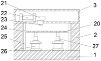
图4为本实用新型提出的一种用于正反面印刷的印刷机构翻转结构的工作台正剖视图。Fig. 4 is a front cross-sectional view of a workbench with a reverse structure of a printing mechanism for front and back printing proposed by the utility model.
图例说明:illustration:
1、底座;2、工作台;3、顶板;4、控制台;5、固定板;6、转动滚轮;7、支撑板;8、主动滚轮;9、支撑柱;10、第一固定螺栓;11、固定块;12、转动电机;13、主动转动电机;14、从动滚轮;15、从动转动电机;16、主动转轴;17、第二固定螺栓;18、第三固定螺栓;19、从动转轴;20、推板;21、墨盒;22、气缸;23、喷嘴;24、滑块;25、滑杆;26、液压气泵;27、液压伸缩柱;28、转动轴;29、挡板。1. Base; 2. Workbench; 3. Top plate; 4. Console; 5. Fixed plate; 6. Rotating roller; 7. Support plate; 8. Active roller; 9. Support column; 10. First fixing bolt; 11, fixed block; 12, rotating motor; 13, active rotating motor; 14, driven roller; 15, driven rotating motor; 16, active rotating shaft; 17, second fixing bolt; 18, third fixing bolt; 19, Driven rotating shaft; 20, push plate; 21, ink cartridge; 22, cylinder; 23, nozzle; 24, slide block; 25, slide bar; 26, hydraulic air pump; plate.
具体实施方式Detailed ways
下面将结合本实用新型实施例中的附图,对本实用新型实施例中的技术方案进行清楚、完整地描述,显然,所描述的实施例仅仅是本实用新型一部分实施例,而不是全部的实施例。基于本实用新型中的实施例,本领域普通技术人员在没有做出创造性劳动前提下所获得的所有其他实施例,都属于本实用新型保护的范围。The technical solutions in the embodiments of the present invention will be clearly and completely described below in conjunction with the accompanying drawings in the embodiments of the present invention. Obviously, the described embodiments are only part of the embodiments of the present invention, not all of them. example. Based on the embodiments of the present utility model, all other embodiments obtained by persons of ordinary skill in the art without making creative efforts belong to the scope of protection of the present utility model.
参照图1-4,本实用新型提供的一种实施例:一种用于正反面印刷的印刷机构翻转结构,包括底座1,底座1顶端两侧均固定设置有支撑板7,底座1顶端靠近两个支撑板7的一侧固定设置有工作台2,底座1顶端两侧靠近工作台2远离两个支撑板7的一侧均固定设置有支撑柱9,两个支撑柱9远离工作台2的一侧之间固定设置有挡板29,支撑板7内部固定设置有转动电机12,转动电机12输出端固定设置有转动轴28,转动轴28固定设置有转动滚轮6,两个支撑板7远离转动电机12一侧固定设置有第一固定螺栓10,两个支撑板7两侧壁靠近转动滚轮6均固定设置有固定块11,两个固定块11固定设置有固定板5,两个支撑柱9内部顶端固定设置有主动转动电机13,主动转动电机13输出端固定设置有主动转轴16,主动转轴16固定设置有主动滚轮8,两个支撑柱9远离主动转动电机13的一侧固定设置有第二固定螺栓17,两个支撑柱9内部靠近主动转动电机13的底端固定设置有两个从动转动电机15,两个从动转动电机15输出端均固定设置有从动转轴19,两个从动转轴19均固定设置有从动滚轮14,两个支撑柱9靠近第二固定螺栓17的底端固定设置两个第三固定螺栓18。Referring to Figures 1-4, an embodiment of the utility model is provided: a printing mechanism flip structure for front and back printing, including a
底座1前端面固定设置有控制台4,工作台2顶端固定设置有顶板3,顶板3内部固定设置有气缸22,气缸22输出端固定设置有墨盒21,墨盒21底端固定设置有喷嘴23,工作台2内部固定设置有两个液压气泵26,两个所述液压气泵26输出端均固定设置有液压伸缩柱27,工作台2内部两侧均固定设置有滑杆25,两个滑杆25均固定设置有滑块24,两个滑块24上滑动设置有推板20。The front end of the
工作原理:使用机器时,工作人员通过控制台4控制机器,将需要印刷的物品放置转动滚轮6传递至固定板5,进入工作台2,工作台2内部的两个液压气泵26通过滑杆25上的滑块24将推板20向上推起,气缸22输出将墨盒21的墨汁通过喷嘴23喷出,印刷好后传至主动滚轮8通过挡板29翻转至两个从动滚轮14,回到工作台2进行再次印刷。Working principle: When using the machine, the staff controls the machine through the
最后应说明的是:以上所述仅为本实用新型的优选实施例而已,并不用于限制本实用新型,尽管参照前述实施例对本实用新型进行了详细的说明,对于本领域的技术人员来说,其依然可以对前述各实施例所记载的技术方案进行修改,或者对其中部分技术特征进行等同替换,凡在本实用新型的精神和原则之内,所作的任何修改、等同替换、改进等,均应包含在本实用新型的保护范围之内。Finally, it should be noted that: the above is only a preferred embodiment of the utility model, and is not intended to limit the utility model, although the utility model has been described in detail with reference to the foregoing embodiments, for those skilled in the art , it can still modify the technical solutions recorded in the foregoing embodiments, or perform equivalent replacements on some of the technical features. Any modifications, equivalent replacements, improvements, etc. made within the spirit and principles of the present utility model, All should be included within the protection scope of the present utility model.
Claims (8)
Priority Applications (1)
| Application Number | Priority Date | Filing Date | Title |
|---|---|---|---|
| CN202222068126.5U CN217778120U (en) | 2022-08-08 | 2022-08-08 | A printing mechanism flip structure for positive and negative printing |
Applications Claiming Priority (1)
| Application Number | Priority Date | Filing Date | Title |
|---|---|---|---|
| CN202222068126.5U CN217778120U (en) | 2022-08-08 | 2022-08-08 | A printing mechanism flip structure for positive and negative printing |
Publications (1)
| Publication Number | Publication Date |
|---|---|
| CN217778120U true CN217778120U (en) | 2022-11-11 |
Family
ID=83942962
Family Applications (1)
| Application Number | Title | Priority Date | Filing Date |
|---|---|---|---|
| CN202222068126.5U Expired - Fee Related CN217778120U (en) | 2022-08-08 | 2022-08-08 | A printing mechanism flip structure for positive and negative printing |
Country Status (1)
| Country | Link |
|---|---|
| CN (1) | CN217778120U (en) |
-
2022
- 2022-08-08 CN CN202222068126.5U patent/CN217778120U/en not_active Expired - Fee Related
Similar Documents
| Publication | Publication Date | Title |
|---|---|---|
| CN107297778B (en) | Efficient paper pressing device used in a kind of paper press | |
| CN101524912A (en) | Multifunctional complex printer | |
| CN211542757U (en) | Roller assembly of double-sided synchronous compound printing machine | |
| CN114801515B (en) | Automatic page-turning printing and evidence-making machine for present certificates | |
| CN113211954B (en) | Double-sided printing machine | |
| CN111170044B (en) | A paper feeder for a printer | |
| CN210680015U (en) | Relief printing device | |
| CN201900775U (en) | A stacked rotary printing machine | |
| CN2834907Y (en) | Paper turnover device for table printing machine | |
| CN218463262U (en) | Energy-concerving and environment-protective carton printing device | |
| CN207390581U (en) | Web paper intaglio printing press Double-station winding device | |
| CN201900779U (en) | A horizontal printing unit of a rotary printing machine | |
| CN214563755U (en) | Double-sided printing device for paperboard processing | |
| CN213505205U (en) | A paper splicing device for a printing press | |
| CN211138565U (en) | An energy-saving thermal paper leveling and printing all-in-one machine | |
| CN218519369U (en) | Auxiliary device of printing machine | |
| CN219055693U (en) | Multicolor gravure printing machine for water-based ink printing film | |
| CN221851475U (en) | Adjustable printing machine | |
| CN210234331U (en) | An oversized printing machine | |
| CN212171592U (en) | A clutch mechanism of a printing press embossing device | |
| CN217863238U (en) | Pressure adjusting device of printing machine | |
| CN214934346U (en) | A green energy-saving printing equipment | |
| CN219859602U (en) | Paper feeding mechanism of offset press | |
| CN222590959U (en) | Pressure regulating device of printing machine | |
| CN219749306U (en) | Three-roller transmission mechanism for printer |
Legal Events
| Date | Code | Title | Description |
|---|---|---|---|
| GR01 | Patent grant | ||
| GR01 | Patent grant | ||
| CP03 | Change of name, title or address |
Address after: 518000 20g, office building, Haiwang building, intersection of Nanyou Avenue Road and Chuangye Road, Yuehai street, Nanshan District, Shenzhen, Guangdong Province Patentee after: Shenzhen Klent Technology Co.,Ltd. Country or region after: China Address before: 518000 20g, office building, Haiwang building, intersection of Nanyou Avenue Road and Chuangye Road, Yuehai street, Nanshan District, Shenzhen, Guangdong Province Patentee before: SHENZHEN COLORTE PRINTING EQUIPMENT CO.,LTD. Country or region before: China |
|
| CP03 | Change of name, title or address | ||
| CF01 | Termination of patent right due to non-payment of annual fee |
Granted publication date: 20221111 |
|
| CF01 | Termination of patent right due to non-payment of annual fee |