CN217776634U - Precise alloy shaft polishing device - Google Patents
Precise alloy shaft polishing device Download PDFInfo
- Publication number
- CN217776634U CN217776634U CN202221854663.6U CN202221854663U CN217776634U CN 217776634 U CN217776634 U CN 217776634U CN 202221854663 U CN202221854663 U CN 202221854663U CN 217776634 U CN217776634 U CN 217776634U
- Authority
- CN
- China
- Prior art keywords
- collar
- fixedly connected
- base
- driving
- polishing device
- Prior art date
- Legal status (The legal status is an assumption and is not a legal conclusion. Google has not performed a legal analysis and makes no representation as to the accuracy of the status listed.)
- Expired - Fee Related
Links
- 239000000956 alloy Substances 0.000 title claims abstract description 48
- 229910045601 alloy Inorganic materials 0.000 title claims abstract description 48
- 238000005498 polishing Methods 0.000 title claims abstract description 35
- 230000007246 mechanism Effects 0.000 claims abstract description 11
- 238000009434 installation Methods 0.000 claims abstract description 8
- 238000012545 processing Methods 0.000 abstract description 3
- 239000000428 dust Substances 0.000 description 3
- 238000000034 method Methods 0.000 description 3
- 230000008859 change Effects 0.000 description 2
- 230000008569 process Effects 0.000 description 2
- 230000001737 promoting effect Effects 0.000 description 2
- 238000012216 screening Methods 0.000 description 2
- 230000008901 benefit Effects 0.000 description 1
- 230000000694 effects Effects 0.000 description 1
- 230000036541 health Effects 0.000 description 1
- 238000004519 manufacturing process Methods 0.000 description 1
- 230000004048 modification Effects 0.000 description 1
- 238000012986 modification Methods 0.000 description 1
- 239000002245 particle Substances 0.000 description 1
- 230000002093 peripheral effect Effects 0.000 description 1
- 238000007517 polishing process Methods 0.000 description 1
- 230000007480 spreading Effects 0.000 description 1
- 239000000126 substance Substances 0.000 description 1
- 238000012546 transfer Methods 0.000 description 1
Images



Landscapes
- Finish Polishing, Edge Sharpening, And Grinding By Specific Grinding Devices (AREA)
Abstract
The utility model discloses an accurate alloy axle burnishing device belongs to alloy processing technology field, the on-line screen storage device comprises a base, base both sides fixedly connected with backup pad, the backup pad top is equipped with fixture, the base is located sliding connection has the mount pad between two backup pads, it is connected with the collar to rotate on the mount pad, the inboard fixedly connected with installation piece of collar, the installation piece is located the inside screw thread of collar and is connected with the connecting rod, the connecting rod is located the collar axis, the one end that the installation piece was kept away from to the connecting rod is equipped with throws aureola, the collar is connected with actuating mechanism. This precision alloy axle burnishing device rotates the collar of connection on the mount pad through setting up and makes the collar can drive the inboard polishing wheel of collar and fix the alloy axle in two backup pads and carry out 360 and polish for the staff need not to take off the alloy axle from fixture alright with polishing in the multi-angle to the alloy axle, has improved the efficiency of polishing.
Description
Technical Field
The utility model belongs to the technical field of the alloy processing, especially, relate to an accurate alloy axle burnishing device.
Background
Polishing refers to a process of reducing the roughness of a workpiece surface by mechanical, chemical, or electrochemical actions to obtain a bright, flat surface. The method is to carry out modification processing on the surface of a workpiece by using a polishing tool and abrasive particles or other polishing media. Polishing does not improve the dimensional or geometric accuracy of the workpiece, but is also sometimes used to eliminate gloss with the aim of obtaining a smooth surface or a mirror finish.
When the precision alloy shaft is ground, the peripheral surface of the alloy shaft needs to be ground in all directions, so that the polishing quality of the alloy shaft is ensured. When polishing the alloy axle among the prior art, because the reaction force that produces when polishing wheel polishes is big, can't hand going on, need carry out the centre gripping through clamping device to the alloy axle and just can polish, this also leads to the staff if want to carry out 360 polishing to the alloy axle when needing to take off the alloy axle from clamping device repeatedly and transfer the direction and fix again, and this process is loaded down with trivial details troublesome, influences polishing efficiency.
Therefore, a precise alloy shaft polishing device is provided to solve the problems.
SUMMERY OF THE UTILITY MODEL
The utility model aims at solving the problem of inconvenient rotation when polishing the alloy shaft in the prior art, and providing a precision alloy shaft polishing device.
In order to achieve the above purpose, the utility model adopts the following technical scheme:
the utility model provides an accurate alloy axle burnishing device, includes the base, base both sides fixedly connected with backup pad, the backup pad top is equipped with fixture, the base is located sliding connection has the mount pad between two backup pads, it is connected with the collar to rotate on the mount pad, the inboard fixedly connected with installation piece of collar, the installation piece is located the inside screw thread of collar and is connected with the connecting rod, the connecting rod is located the collar axis, the one end that the installation piece was kept away from to the connecting rod is equipped with throws aureola, the collar is connected with actuating mechanism.
Preferably, the base is located and fixedly connected with shielding cover between two backup pads, shielding cover sets up in the collar outside.
Preferably, the clamping mechanism comprises a driving screw rod which is rotatably connected to the vertical position above the shielding cover, a movable plate is arranged above the shielding cover, clamping plates are fixedly connected to two sides of the movable plate and are arranged opposite to the supporting plate, and the driving screw rod penetrates through the movable plate and is in threaded connection with the movable plate.
Preferably, the shielding cover is fixedly connected with a limiting rod, the limiting rod is arranged in parallel with the driving screw rod, and the limiting rod penetrates through the movable plate and is connected with the movable plate in a sliding manner.
Preferably, a fixing block is fixedly connected to the lower portion of the shielding cover and is rotatably connected with the mounting ring.
Preferably, actuating mechanism is including rotating the drive shaft of connecting in mount pad one side, fixedly connected with gear in the drive shaft, the cover is equipped with the ring gear in the mount ring outside, ring gear and mount ring fixed connection, ring gear and gear engagement, the drive shaft is connected with the driving piece.
Preferably, the driving part comprises a worm wheel fixedly connected to the driving shaft, a worm is rotatably connected to the mounting seat and meshed with the worm wheel, and one end, far away from the worm wheel, of the worm penetrates through the shielding cover and is fixedly connected with the driving handle.
Preferably, the base is fixedly connected with a limiting strip, a limiting groove is formed below the mounting seat, and the limiting strip is located in the limiting groove and is in sliding connection with the mounting seat.
To sum up, the utility model discloses a technological effect and advantage: this precision alloy axle burnishing device, rotate the collar of connection on the mount pad through setting up, and rotate through actuating mechanism drive collar, make the collar can drive the polishing wheel that is located the collar inboard and fix the alloy axle in two backup pads and carry out 360 and polish, make the staff need not to take off the alloy axle from fixture alright polish with carrying out the multi-angle to the alloy axle, the time of alloy axle when having saved the staff and polishing, the efficiency of polishing has been improved, it can also shelter from to the dust that grinds the production to shelter from the cover simultaneously, the dust is scattered when reducing and is led to the fact harm to staff's health.
Drawings
FIG. 1 is a schematic view of the present invention;
FIG. 2 is a schematic view of the front view structure of the present invention;
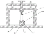
fig. 3 is a front sectional view of the present invention;
fig. 4 is a side sectional view of the present invention.
In the figure: 1. a base; 2. a support plate; 3. a mounting seat; 4. a mounting ring; 5. a connecting rod; 6. mounting blocks; 7. a polishing wheel; 8. a shield cover; 9. a drive screw; 10. a movable plate; 11. a clamping plate; 12. a limiting rod; 13. a fixed block; 14. a drive shaft; 15. a gear; 16. a toothed ring; 17. a worm gear; 18. a worm; 19. a drive handle; 20. a limiting strip; 21. a limiting groove.
Detailed Description
The technical solutions in the embodiments of the present invention will be described clearly and completely with reference to the accompanying drawings in the embodiments of the present invention, and it is obvious that the described embodiments are only some embodiments of the present invention, not all embodiments.
Referring to fig. 1, 2, 3, a precision alloy axle burnishing device, includes base 1, the backup pad 2 of the vertical setting of base 1 both sides fixedly connected with, 2 tops of backup pad are equipped with fixture, fix alloy axle centre gripping in base 1 top through fixture, base 1 is located sliding connection between two backup pads 2 and has mount pad 3, it is connected with collar 4 to rotate on mount pad 3, and collar 4 is on a parallel with backup pad 2, the inboard fixedly connected with installing block 6 of collar 4, installing block 6 is located 4 inboard threaded connection of collar has connecting rod 5, connecting rod 5 is located 4 axises of collar, the one end that mounting block 6 was kept away from to connecting rod 5 is equipped with throwing aureola 7, can polish the polishing to the alloy axle that is located in the middle of collar 4 through throwing aureola 7, collar 4 is connected with actuating mechanism for drive collar 4 rotates.
This precision alloy axle burnishing device firmly fixes the alloy axle in base 1 top through fixture, and rethread actuating mechanism drives collar 4 and rotates to collar 4 drives polishing wheel 7 and rotates around closing Jin Zhou, thereby polishes 360 to the alloy axle.
Referring to fig. 1, 2 and 3, the base 1 is located fixedly connected with shielding cover 8 between two supporting plates 2, the shielding cover 8 is sleeved outside the mounting ring 4, flying chips generated in the polishing process are shielded through the shielding cover 8, and feeding is carried out to prevent dust from spreading to cause harm to workers.
The fixture is including rotating the drive screw 9 of connecting the vertical setting in the cover 8 top, cover 8 tops and be equipped with fly leaf 10, fly leaf 10 both sides fixedly connected with grip block 11, grip block 11 sets up with backup pad 2 relatively, and grip block 11 and 2 adjacent sides of backup pad all are equipped with the arc wall, can carry out the centre gripping to the alloy axle when grip block 11 is close to with backup pad 2, drive screw 9 passes fly leaf 10 and fly leaf 10 threaded connection, rotates drive screw 9 and can drive fly leaf 10 and be close to or keep away from cover 8 to carry out the centre gripping through grip block 11 to the alloy axle or loosen. The shielding cover 8 is fixedly connected with a limiting rod 12, the limiting rod 12 is arranged in parallel with the driving screw 9, the limiting rod 12 penetrates through the movable plate 10 to be slidably connected with the movable plate 10, and the limiting rod 12 limits the movable plate 10, so that the driving screw 9 does not drive the movable plate 10 to rotate but drives the movable plate 10 to move when rotating.
Referring to fig. 1, 3 and 4, a fixing block 13 is fixedly connected to the lower portion of the shielding cover 8, the fixing block 13 is rotatably connected to the mounting ring 4, and the fixing block 13 further limits the mounting ring 4.
The actuating mechanism includes that rotation connects the drive shaft 14 in mount pad 3 one side, and drive shaft 14 perpendicular to ring gear 16 place plane, fixedly connected with gear 15 on the drive shaft 14, the cover is equipped with ring gear 16 outside the mount ring 4, ring gear 16 and mount ring 4 fixed connection, ring gear 16 and gear 15 mesh, can drive ring gear 16 when gear 15 rotates and rotate to make mount ring 4 rotate.
Spacing 20 of fixedly connected with on the base 1, spacing 20 perpendicular to backup pad 2, spacing groove 21 has been seted up to mount pad 3 below, spacing 20 is located spacing inslot 21 and 3 sliding connection of mount pad, and spacing 20 and spacing groove 21 cooperation are spacing to mount pad 3 for can drive mount pad 3 along spacing 20 slip through promoting drive handle 19.
The working principle is as follows: during the use, place the alloy axle on two backup pads 2 through the screening cover 8, then rotate drive screw 9 and drive fly leaf 10 and be close to screening cover 8, the grip block 11 through fly leaf 10 both sides carries out the centre gripping to the alloy axle and fixes, then start polishing wheel 7 and polish the alloy axle, when needs change polishing angle, it rotates drive handle 19 and drives worm 18 and rotate to drive worm wheel 17 and drive gear 15 and rotate, gear 15 rotates and makes ring gear 16 rotate, and then make collar 4 rotate, change polishing wheel 7's polishing angle, worm wheel 17 and worm 18 can realize the auto-lock when stall drive handle 19, rotate by oneself when avoiding collar 4 to polish as far as possible, carry out diversified polishing to the alloy axle, still can drive mount pad 3 through promoting drive handle 19 simultaneously and slide along spacing strip 20, make mount pad 3 slide along alloy axle length direction and polish the alloy axle.
The above, only be the embodiment of the preferred of the present invention, but the protection scope of the present invention is not limited thereto, and any person skilled in the art is in the technical scope of the present invention, according to the technical solution of the present invention and the utility model, which are designed to be replaced or changed equally, all should be covered within the protection scope of the present invention.
Claims (8)
1. The utility model provides a precision alloy axle burnishing device, includes base (1), its characterized in that, base (1) both sides fixedly connected with backup pad (2), backup pad (2) top is equipped with fixture, sliding connection has mount pad (3) between base (1) is located two backup pad (2), it is connected with collar (4) to rotate on mount pad (3), inboard fixedly connected with installation piece (6) of collar (4), installation piece (6) are located collar (4) inboard threaded connection and have connecting rod (5), connecting rod (5) are located collar (4) axis, the one end that mounting piece (6) were kept away from in connecting rod (5) is equipped with throwing aureola (7), collar (4) are connected with actuating mechanism.
2. The precision alloy shaft polishing device according to claim 1, wherein a shielding cover (8) is fixedly connected between the two supporting plates (2) of the base (1), and the shielding cover (8) is sleeved outside the mounting ring (4).
3. The precise alloy shaft polishing device according to claim 2, wherein the clamping mechanism comprises a driving screw (9) rotatably connected to a vertical position above the shielding cover (8), a movable plate (10) is arranged above the shielding cover (8), clamping plates (11) are fixedly connected to two sides of the movable plate (10), the clamping plates (11) are arranged opposite to the supporting plate (2), and the driving screw (9) penetrates through the movable plate (10) to be in threaded connection with the movable plate (10).
4. A precision alloy shaft polishing device according to claim 3, wherein a limiting rod (12) is fixedly connected to the shielding cover (8), the limiting rod (12) is arranged in parallel with the driving screw (9), and the limiting rod (12) passes through the movable plate (10) and is slidably connected with the movable plate (10).
5. A precision alloy shaft polishing device according to claim 2, characterized in that a fixed block (13) is fixedly connected below the shielding cover (8), and the fixed block (13) is rotatably connected with the mounting ring (4).
6. A precision alloy shaft polishing device according to claim 1, characterized in that the driving mechanism comprises a driving shaft (14) rotatably connected to one side of the mounting seat (3), a gear (15) is fixedly connected to the driving shaft (14), a toothed ring (16) is sleeved on the outer side of the mounting ring (4), the toothed ring (16) is fixedly connected to the mounting ring (4), the toothed ring (16) is meshed with the gear (15), and a driving member is connected to the driving shaft (14).
7. A precision alloy shaft polishing device according to claim 6, characterized in that the driving member comprises a worm wheel (17) fixedly connected to the driving shaft (14), a worm (18) is rotatably connected to the mounting seat (3), the worm (18) is meshed with the worm wheel (17), and one end of the worm (18) far away from the worm wheel (17) penetrates through the shielding cover (8) and is fixedly connected with a driving handle (19).
8. The precision alloy shaft polishing device according to claim 1, wherein a limiting strip (20) is fixedly connected to the base (1), a limiting groove (21) is formed below the mounting seat (3), and the limiting strip (20) is located in the limiting groove (21) and is in sliding connection with the mounting seat (3).
Priority Applications (1)
| Application Number | Priority Date | Filing Date | Title |
|---|---|---|---|
| CN202221854663.6U CN217776634U (en) | 2022-07-19 | 2022-07-19 | Precise alloy shaft polishing device |
Applications Claiming Priority (1)
| Application Number | Priority Date | Filing Date | Title |
|---|---|---|---|
| CN202221854663.6U CN217776634U (en) | 2022-07-19 | 2022-07-19 | Precise alloy shaft polishing device |
Publications (1)
| Publication Number | Publication Date |
|---|---|
| CN217776634U true CN217776634U (en) | 2022-11-11 |
Family
ID=83941670
Family Applications (1)
| Application Number | Title | Priority Date | Filing Date |
|---|---|---|---|
| CN202221854663.6U Expired - Fee Related CN217776634U (en) | 2022-07-19 | 2022-07-19 | Precise alloy shaft polishing device |
Country Status (1)
| Country | Link |
|---|---|
| CN (1) | CN217776634U (en) |
Cited By (1)
| Publication number | Priority date | Publication date | Assignee | Title |
|---|---|---|---|---|
| CN119910556A (en) * | 2025-03-10 | 2025-05-02 | 江苏酷聚合金科技有限公司 | Surface polishing equipment for curved alloy parts |
-
2022
- 2022-07-19 CN CN202221854663.6U patent/CN217776634U/en not_active Expired - Fee Related
Cited By (1)
| Publication number | Priority date | Publication date | Assignee | Title |
|---|---|---|---|---|
| CN119910556A (en) * | 2025-03-10 | 2025-05-02 | 江苏酷聚合金科技有限公司 | Surface polishing equipment for curved alloy parts |
Similar Documents
| Publication | Publication Date | Title |
|---|---|---|
| CN213998796U (en) | Grinding device of bearing with adjustable | |
| CN216179140U (en) | Stainless steel processing burr equipment of polishing | |
| CN115837624A (en) | Auxiliary polishing device for automobile crankshaft | |
| CN114454079A (en) | Equipment surface layer precision polishing device for machining production | |
| CN217668596U (en) | Buckle ring processing device | |
| CN219152355U (en) | Full-automatic grinding machine for grinding taper holes on main shaft | |
| CN216657382U (en) | Transport vechicle sheet metal component grinding tool | |
| CN207495233U (en) | A kind of burnishing device of machine components | |
| CN212527200U (en) | Grinding device is used in spare part processing | |
| CN214025205U (en) | Precision finishing is with automatic assembly line | |
| CN211728561U (en) | Grinding machine with grinding wheel adjusting device | |
| CN217194320U (en) | A centerless grinder for processing conical parts | |
| CN213054118U (en) | Fixing device for grinding machine for auto-parts machining | |
| CN115990830A (en) | Surface polishing equipment for processing aluminum alloy profiles | |
| CN211465872U (en) | Machining high-precision grinding machine | |
| CN211966855U (en) | High-speed roller grinding device | |
| CN209503789U (en) | A kind of aluminum oxide ceramic curved surface polishing device | |
| CN110653426B (en) | Gear grinding processing equipment | |
| CN222078923U (en) | 2060mm wide metal billet surface oxide polishing equipment | |
| CN209477862U (en) | A kind of floor stand grinder for steel watchcase of polishing | |
| CN221735592U (en) | Diamond blade polishing device | |
| CN220348074U (en) | Production burnishing and polishing device of anti-drop hundred impeller | |
| CN215968043U (en) | Novel polishing and grinding machine | |
| CN222243919U (en) | A metal processing grinding machine | |
| CN215317817U (en) | Brake wheel grinding device convenient to consumptive material is changed |
Legal Events
| Date | Code | Title | Description |
|---|---|---|---|
| GR01 | Patent grant | ||
| GR01 | Patent grant | ||
| CF01 | Termination of patent right due to non-payment of annual fee |
Granted publication date: 20221111 |
|
| CF01 | Termination of patent right due to non-payment of annual fee |