CN217776104U - A circular welding adjustment device for round pipe butt welding - Google Patents
A circular welding adjustment device for round pipe butt welding Download PDFInfo
- Publication number
- CN217776104U CN217776104U CN202221726152.6U CN202221726152U CN217776104U CN 217776104 U CN217776104 U CN 217776104U CN 202221726152 U CN202221726152 U CN 202221726152U CN 217776104 U CN217776104 U CN 217776104U
- Authority
- CN
- China
- Prior art keywords
- welding
- support
- round pipe
- welded
- circumferential
- Prior art date
- Legal status (The legal status is an assumption and is not a legal conclusion. Google has not performed a legal analysis and makes no representation as to the accuracy of the status listed.)
- Active
Links
Images



Landscapes
- Butt Welding And Welding Of Specific Article (AREA)
Abstract
Description
技术领域technical field
本实用新型涉及钢结构支撑体系技术领域,特别的涉及一种圆管对焊用环向焊接调节装置。The utility model relates to the technical field of steel structure support systems, in particular to a ring-direction welding adjustment device for round pipe butt welding.
背景技术Background technique
桥梁重建施工常常采用大量钢结构以形成桥梁的基础支撑和上部支撑。圆管作为钢结构的重要组成之一,施工人员往往需要现场对多个圆管焊接组合以符合设计要求的长度,这种焊接基本都是采用将圆管端面对齐后进行环向焊接。对于这类环形焊缝作业,焊接工人需要根据焊接部位的位置改变来调整自己的身体姿态并进行焊接作业,操作十分不方便。同时在对圆管底部等隐蔽位置进行焊接时,则需要汽车吊等起吊设备先将两圆管吊起翻身并暴露相应部位后方可进行焊接,但是此时由于整体环向焊缝未完全焊接完成,在翻身过程中可能会造成圆管在焊接处弯折。同时对于圆管底部的焊缝会因为焊接角度不对导致焊缝存在肉眼无法判断的缺陷,影响整体刚性。Bridge reconstruction often uses a large number of steel structures to form the base support and upper support of the bridge. Round pipes are one of the important components of steel structures. Construction personnel often need to weld multiple round pipes on site to meet the length required by the design. This type of welding is basically performed by aligning the end faces of the round pipes and performing circumferential welding. For this type of circular weld operation, the welder needs to adjust his body posture and perform the welding operation according to the position change of the welding part, which is very inconvenient to operate. At the same time, when welding hidden positions such as the bottom of the round pipe, lifting equipment such as a truck crane is required to lift the two round pipes and expose the corresponding parts before welding. However, at this time, the overall circumferential weld is not completely welded. , the round tube may be bent at the weld during the turning process. At the same time, the welding seam at the bottom of the round pipe will have defects that cannot be judged by naked eyes due to the wrong welding angle, which will affect the overall rigidity.
实用新型内容Utility model content
针对现有技术存在的不足,本实用新型的目的在于提供一种圆管对焊用环向焊接调节装置,本实用新型结构简单,能够有效对待焊接或焊接过程中的圆管进行位置调节,提高环向焊接的工作效率和质量。Aiming at the deficiencies in the prior art, the purpose of this utility model is to provide a circular welding adjustment device for round pipe butt welding. The utility model has a simple structure and can effectively adjust the position of the round pipe to be welded or in the welding process, improving Productivity and quality of circumferential welding.
为实现上述目的,本实用新型提供了如下技术方案:In order to achieve the above object, the utility model provides the following technical solutions:
一种圆管对焊用环向焊接调节装置,包括长度方向沿待焊接圆管轴向延伸设置的支撑底座,支撑底座顶部两长度方向侧壁竖直向上延伸且等高设有支撑板,两所述支撑板上与对应位置处设有可供待焊接圆管周向转动的定滑轮;A circumferential welding adjustment device for round pipe butt welding, comprising a support base extending along the axial direction of the round pipe to be welded in the length direction, the two length direction side walls of the top of the support base extend vertically upwards and are provided with support plates at the same height. The supporting plate and the corresponding position are provided with a fixed pulley for the circumferential rotation of the round pipe to be welded;
所述支撑底座内部还设有数个用于对待焊接圆管提供临时竖直向支撑的移动支撑机构,所述移动支撑机构的输出端穿过支撑底座顶面预留的通孔后暴露至两所述支撑板之间,The inside of the support base is also provided with several mobile support mechanisms for providing temporary vertical support to the round pipe to be welded. between the support plates,
所述支撑底座的侧壁上对应所述移动支撑机构处开设有操作孔,所述操作孔连通外界和支撑底座的内部空间。An operation hole is opened on the side wall of the support base corresponding to the mobile support mechanism, and the operation hole communicates with the outside world and the inner space of the support base.
优选的,所述移动支撑机构的输出端包括移动卡板,所述移动卡板暴露至外界的顶端固定连接有用于转动支撑托辊组的托辊支架。Preferably, the output end of the moving support mechanism includes a moving clamping plate, and the top end of the moving clamping plate exposed to the outside world is fixedly connected with an idler bracket for rotatably supporting the idler roller set.
优选的,所述托辊组包括两呈底部对向倾斜、顶部背向远离设置的托辊,托辊通过辊轴与所述托辊支架转动连接。Preferably, the set of idler rollers includes two idler rollers whose bottoms are oppositely inclined and whose tops are facing away from each other, and the idler rollers are rotatably connected to the idler support through roller shafts.
优选的,所述移动卡板的底端开设有竖直向延伸的螺纹孔,所述螺纹孔与螺纹柱顶部螺配,螺纹柱底部转动设置于支撑底座的底板上。Preferably, a vertically extending threaded hole is provided at the bottom end of the moving pallet, the threaded hole is screwed with the top of the threaded column, and the bottom of the threaded column is rotatably arranged on the bottom plate of the supporting base.
优选的,所述螺纹柱的外壁还径向延伸设有数根呈周向等间距设置的手杆。Preferably, the outer wall of the threaded column is also radially extended with several hand rods arranged at equal intervals in the circumferential direction.
优选的,所述装置还包括设置于支撑底座长度方向两端的定位机构,所述定位机构包括水平滑动连接于两支撑板之间的滑动块,滑动块朝向待焊接圆管的侧面铰接有两平行设置的铰接杆,铰接杆的另一端铰接有连接板,连接板底部垂直设有固定横板,底部转动设置于固定横板上的螺纹轴与移动板上的预设螺孔螺配。两平行设置的铰接杆可以保持连接板尽可能的处于竖直状态,保证固定横板配合连接板可以有效对待焊接圆管管壁进行夹持。Preferably, the device further includes a positioning mechanism arranged at both ends of the support base in the length direction, the positioning mechanism includes a sliding block horizontally slidably connected between the two supporting plates, and the sliding block is hinged with two parallel bars facing the side of the round pipe to be welded. The other end of the hinged rod is hinged with a connecting plate, and the bottom of the connecting plate is vertically provided with a fixed horizontal plate, and the threaded shaft arranged on the fixed horizontal plate at the bottom is screwed with the preset screw hole on the movable plate. The two hinged rods arranged in parallel can keep the connecting plate in a vertical state as much as possible, ensuring that the fixed horizontal plate cooperates with the connecting plate to effectively clamp the pipe wall of the round pipe to be welded.
优选的,所述连接板上开设有燕尾滑槽,所述燕尾滑槽与移动板端部设置的燕尾滑块滑动配合。燕尾滑槽和燕尾滑块的配合,可以保证连接板相对固定横板进行竖直向的平稳移动。Preferably, a dovetail chute is opened on the connecting plate, and the dovetail chute is slidingly matched with the dovetail slider provided at the end of the moving plate. The cooperation of the dovetail chute and the dovetail slider can ensure that the connecting plate moves vertically and smoothly relative to the fixed horizontal plate.
本实用新型工作过程如下:The utility model work process is as follows:
首先通过手杆307转动螺纹柱306,使得移动卡板301上升并使得托辊支架302的高度高出支撑板101,然后利用汽车吊将两圆管吊运至支撑底座1上,并利用数个托辊支架302上的托辊组304来对圆管进行支撑,由于托辊组304的两托辊303呈V字形结构,所以两圆管在托辊组304上可以利用重力实现轴线对齐作业。然后对向推动两圆管,使得两圆管在托辊组304上对向移动完成端口对接。First, the threaded
操作人员此刻通过手杆307反向转动螺纹柱306,使得移动卡板301下降并使得托辊支架302的低于支撑板101,利用支撑板101的上定滑轮2对圆管进行支撑,然后移动滑动块401,并转动铰接杆402使得圆管的非焊接端口处管壁置于固定横板403和移动板407之间,然后转动螺纹轴408使得移动板407朝向固定横板403移动并对管壁进行夹持,如此配合滑动块401可以有效防止圆管在外力作用下发生周转,充分保证焊接人员的人身安全。At this moment, the operator rotates the threaded
然后焊接人员即可对暴露在焊接空间内的端口缝隙进行焊接。当前焊缝作业完毕后,工作人员首先将撤除移动板407和固定横板403对圆管的夹持,然后通过定滑轮2的导向使得两圆管同步周向转动并将未焊接的缝隙暴露至焊接空间内,然后再次固定圆管,即可对剩余缝隙进行焊接。焊接完毕后的圆管在撤除夹持后,即可通过汽车吊吊离支撑底座1,并换上新的圆管进行焊接作业。The welder can then weld the port gaps exposed in the weld space. After the current welding seam operation is completed, the staff will first remove the clamping of the circular pipe by the
本实用新型与现有技术相比,具有如下优点:本实用新型结构简单,能够有效对待焊接或焊接过程中的圆管进行位置调节,提高环向焊接的工作效率和质量。Compared with the prior art, the utility model has the following advantages: the utility model has a simple structure, can effectively adjust the position of the round pipe to be welded or in the welding process, and improve the working efficiency and quality of the circumferential welding.
附图说明Description of drawings
图1为具体实施方式中圆管对焊用环向焊接调节装置的结构示意图;Fig. 1 is the structural representation of circular pipe butt welding circular welding adjustment device in the specific embodiment;
图2为具体实施方式中支撑底座1的内部结构示意图;Fig. 2 is a schematic diagram of the internal structure of the
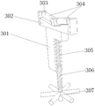
图3为具体实施方式中移动支撑机构的结构示意图;Fig. 3 is a schematic structural view of a mobile support mechanism in a specific embodiment;
图4为具体实施方式中定位机构的结构示意图。Fig. 4 is a schematic structural diagram of a positioning mechanism in a specific embodiment.
具体实施方式Detailed ways
为了使本实用新型的目的、技术方案及优点更加清楚明白,以下结合附图及实施例,对本实用新型进行进一步详细说明。应当理解,此处所描述的具体实施例仅仅用以解释本实用新型,并不用于限定本实用新型。In order to make the purpose, technical solution and advantages of the utility model clearer, the utility model will be further described in detail below in conjunction with the accompanying drawings and embodiments. It should be understood that the specific embodiments described here are only used to explain the utility model, and are not intended to limit the utility model.
如图1-4所示,一种圆管对焊用环向焊接调节装置,包括长度方向沿待焊接圆管轴向延伸设置的支撑底座1,支撑底座1顶部两长度方向侧壁竖直向上延伸且等高设有支撑板101,两所述支撑板101上与对应位置处设有可供待焊接圆管周向转动的定滑轮2;As shown in Figure 1-4, a circular pipe butt welding circular welding adjustment device includes a
所述支撑底座1内部还设有数个用于对待焊接圆管提供临时竖直向支撑的移动支撑机构3,所述移动支撑机构3包括移动卡板301,移动卡板301顶部穿过支撑底座1顶面预留的通孔后暴露至两所述支撑板101之间的外界空间处,移动卡板301顶端固定连接有用于转动支撑托辊组304的托辊支架302,所述托辊组304包括两呈底部对向倾斜、顶部背向远离设置的托辊303,托辊303通过辊轴与所述托辊支架302转动连接。The inside of the
所述移动卡板301的底端开设有竖直向延伸的螺纹孔305,所述螺纹孔305与螺纹柱306顶部螺配,螺纹柱306底部转动设置于支撑底座1的底板上,所述螺纹柱306的外壁还径向延伸设有数根呈周向等间距设置的手杆307。The bottom end of the moving
所述支撑底座1的侧壁上对应所述移动支撑机构3处开设有操作孔102,所述操作孔102连通外界和支撑底座1的内部空间。An
所述装置还包括设置于支撑底座1长度方向两端的定位机构4,所述定位机构4包括水平滑动连接于两支撑板101之间的滑动块401,滑动块401朝向待焊接圆管的侧面铰接有两平行设置的铰接杆402,铰接杆402的另一端铰接有连接板403连接板403底部垂直设有固定横板404,底部转动设置于固定横板404上的螺纹轴408与移动板407上的预设螺孔螺配;所述连接板403上开设有燕尾滑槽405,所述燕尾滑槽405与移动板407端部设置的燕尾滑块406滑动配合。The device also includes a
本实用新型工作过程如下:The utility model work process is as follows:
首先通过手杆307转动螺纹柱306,使得移动卡板301上升并使得托辊支架302的高度高出支撑板101,然后利用汽车吊将两圆管吊运至支撑底座1上,并利用数个托辊支架302上的托辊组304来对圆管进行支撑,由于托辊组304的两托辊303呈V字形结构,所以两圆管在托辊组304上可以利用重力实现轴线对齐作业。然后对向推动两圆管,使得两圆管在托辊组304上对向移动完成端口对接。First, the threaded
操作人员此刻通过手杆307反向转动螺纹柱306,使得移动卡板301下降并使得托辊支架302的低于支撑板101,利用支撑板101的上定滑轮2对圆管进行支撑,然后移动滑动块401,并转动铰接杆402使得圆管的非焊接端口处管壁置于固定横板403和移动板407之间,然后转动螺纹轴408使得移动板407朝向固定横板403移动并对管壁进行夹持,如此配合滑动块401可以有效防止圆管在外力作用下发生周转,充分保证焊接人员的人身安全。At this moment, the operator rotates the threaded
然后焊接人员即可对暴露在焊接空间内的端口缝隙进行焊接。当前焊缝作业完毕后,工作人员首先将撤除移动板407和固定横板403对圆管的夹持,然后通过定滑轮2的导向使得两圆管同步周向转动并将未焊接的缝隙暴露至焊接空间内,然后再次固定圆管,即可对剩余缝隙进行焊接。焊接完毕后的圆管在撤除夹持后,即可通过汽车吊吊离支撑底座1,并换上新的圆管进行焊接作业。The welder can then weld the port gaps exposed in the weld space. After the current welding seam operation is completed, the staff will first remove the clamping of the circular pipe by the
Claims (7)
Priority Applications (1)
| Application Number | Priority Date | Filing Date | Title |
|---|---|---|---|
| CN202221726152.6U CN217776104U (en) | 2022-07-06 | 2022-07-06 | A circular welding adjustment device for round pipe butt welding |
Applications Claiming Priority (1)
| Application Number | Priority Date | Filing Date | Title |
|---|---|---|---|
| CN202221726152.6U CN217776104U (en) | 2022-07-06 | 2022-07-06 | A circular welding adjustment device for round pipe butt welding |
Publications (1)
| Publication Number | Publication Date |
|---|---|
| CN217776104U true CN217776104U (en) | 2022-11-11 |
Family
ID=83939288
Family Applications (1)
| Application Number | Title | Priority Date | Filing Date |
|---|---|---|---|
| CN202221726152.6U Active CN217776104U (en) | 2022-07-06 | 2022-07-06 | A circular welding adjustment device for round pipe butt welding |
Country Status (1)
| Country | Link |
|---|---|
| CN (1) | CN217776104U (en) |
-
2022
- 2022-07-06 CN CN202221726152.6U patent/CN217776104U/en active Active
Similar Documents
| Publication | Publication Date | Title |
|---|---|---|
| CN110561003B (en) | A workpiece moving, lifting, clamping and position-changing welding mechanism | |
| CN105945498B (en) | A large cylindrical shell assembly and flip welding platform | |
| CN216882536U (en) | Be used for fixed butt joint frock of pressure vessel head welded | |
| CN215091758U (en) | Positioning device for automatic straight seam welding machines | |
| CN221658432U (en) | A steel structure butt welding adjustment device | |
| CN114310016A (en) | Be used for steel construction fulcrum welding set | |
| KR101397939B1 (en) | Welding device | |
| CN116652511A (en) | A ship large-diameter round pipe welding machine and its welding method | |
| CN115870685A (en) | An adjustable welding auxiliary tooling for frame production | |
| CN115026508A (en) | Box steel displacement device and box steel manufacturing method | |
| CN212239748U (en) | Quick welding device for aluminum cell cover plate | |
| CN206335315U (en) | A kind of automatic welding positioner | |
| CN104759772A (en) | General assembling and welding apparatus for steel tube bundle | |
| CN209954054U (en) | Auxiliary transfer device for steel pipe welding machine tool | |
| CN114932368A (en) | Automatic assembling and welding equipment for partition plate in box column | |
| CN215545960U (en) | Laser cutting machine capable of achieving accurate positioning | |
| CN210081063U (en) | Rotary welding platform | |
| CN214518174U (en) | A portable welding device with quick installation function | |
| CN209867720U (en) | Pipeline semi-automatic welding device | |
| CN206854929U (en) | Pipe prefabrication 3D automatic welders | |
| CN220427403U (en) | Pipeline welding auxiliary mechanism | |
| CN119734036B (en) | Steel pipe pole girth welding frock that can carry out supplementary butt joint | |
| CN113199187A (en) | Device for welding grid steel frame and welding method | |
| CN222971327U (en) | Clamping device for welding metal parts | |
| CN221695875U (en) | Circular seam welding device |
Legal Events
| Date | Code | Title | Description |
|---|---|---|---|
| GR01 | Patent grant | ||
| GR01 | Patent grant |