CN217775777U - Slotting device for decoration - Google Patents
Slotting device for decoration Download PDFInfo
- Publication number
- CN217775777U CN217775777U CN202221775531.4U CN202221775531U CN217775777U CN 217775777 U CN217775777 U CN 217775777U CN 202221775531 U CN202221775531 U CN 202221775531U CN 217775777 U CN217775777 U CN 217775777U
- Authority
- CN
- China
- Prior art keywords
- regulating plate
- drive shaft
- articulated seat
- slotting
- drive
- Prior art date
- Legal status (The legal status is an assumption and is not a legal conclusion. Google has not performed a legal analysis and makes no representation as to the accuracy of the status listed.)
- Expired - Fee Related
Links
Images


Landscapes
- Toys (AREA)
Abstract
Description
技术领域technical field
本实用新型涉及开槽装置技术领域,具体为一种装饰装修用开槽装置。The utility model relates to the technical field of slotting devices, in particular to a slotting device for decoration.
背景技术Background technique
铝塑板已经渐渐进入到每个人的居室装饰中,尤其是其表面光滑、色彩艳丽、耐冲击力强、施工快捷等特征被广泛采用,铝塑板这类产品十分容易加工,铝塑板可以切割、裁切、开槽等工艺加工,铝塑板易加工做造型的板材,是一种新型的建筑装饰材料,被广泛运用,在加工造型的时候需要对铝塑板开槽,开槽装置在装饰装修板材加工领域中有着重要的应用。Aluminum-plastic panels have gradually entered everyone's room decoration, especially because of their smooth surface, bright colors, strong impact resistance, and quick construction. Products such as aluminum-plastic panels are very easy to process. Aluminum-plastic panels can be Cutting, cutting, grooving and other processes, the aluminum-plastic panel is easy to process and make a shape plate. It is a new type of building decoration material and is widely used. When processing the shape, it is necessary to groove the aluminum-plastic panel. The slotting device It has an important application in the field of decorative panel processing.
现今市场上的此类开槽装置种类繁多,基本可以满足人们的使用需求,但是依然存在一定的问题,现有的此类开槽装置在使用时一般不便于自动的转动移动开槽加工,大大的影响了开槽装置使用时的便利性,给装饰装修板材的加工效率带来了很大的影响。There are many kinds of such slotting devices on the market today, which can basically meet the needs of people, but there are still certain problems. The existing slotting devices are generally not convenient for automatic rotation, movement and slotting during use, which greatly It affects the convenience of the slotting device, and has a great impact on the processing efficiency of decorative panels.
实用新型内容Utility model content
本实用新型的目的在于提供一种装饰装修用开槽装置,以解决上述背景技术中提出开槽装置不便于对装饰装修板材自动的转动移动开槽加工的问题。The purpose of this utility model is to provide a slotting device for decoration, so as to solve the problem that the slotting device is not convenient for automatic rotation, movement and slotting of decorative panels in the above background technology.
为实现上述目的,本实用新型提供如下技术方案:一种装饰装修用开槽装置,包括基座和铰接座,所述基座的顶端安装有铰接座,所述铰接座的顶端设有调节板,所述调节板的底端设有支撑轴,且调节板通过支撑轴与铰接座活动连接,所述调节板的顶端安装有驱动轴,所述驱动轴的表面套装有护套,所述驱动轴的外壁上安装有加厚开槽刀,所述铰接座一侧的基座顶端安装有卡座,所述卡座的顶端设有伸缩驱动件,所述伸缩驱动件的顶端设有推杆,所述推杆的顶端安装有驱动杆,且驱动杆与调节板固定连接。In order to achieve the above purpose, the utility model provides the following technical solutions: a slotting device for decoration, including a base and a hinged seat, the top of the base is equipped with a hinged seat, and the top of the hinged seat is provided with an adjustment plate , the bottom end of the adjustment plate is provided with a support shaft, and the adjustment plate is movably connected with the hinge seat through the support shaft, the top of the adjustment plate is equipped with a drive shaft, the surface of the drive shaft is covered with a sheath, and the drive A thickened slotting knife is installed on the outer wall of the shaft, a deck is installed on the top of the base on one side of the hinge seat, and a telescopic drive is provided on the top of the deck, and a push rod is provided on the top of the telescopic drive , a driving rod is installed on the top of the push rod, and the driving rod is fixedly connected with the adjusting plate.
优选的,所述驱动轴表面远离加厚开槽刀的一端安装有从动轮,且驱动轴与从动轮固定连接。Preferably, a driven wheel is installed on the surface of the drive shaft away from the thickened slotting knife, and the drive shaft is fixedly connected to the driven wheel.
优选的,所述从动轮一侧的调节板顶端安装有旋转驱动件,所述旋转驱动件的输出端安装有主动轮。Preferably, the top end of the adjustment plate on the side of the driven wheel is installed with a rotary driving member, and the output end of the rotary driving member is installed with a driving wheel.
优选的,所述主动轮的表面设有皮带,且皮带的一端延伸至从动轮的表面。Preferably, a belt is provided on the surface of the driving wheel, and one end of the belt extends to the surface of the driven wheel.
优选的,所述加厚开槽刀两侧的基座顶端皆安装有夹持架,所述夹持架的顶端皆安装有螺纹套。Preferably, the top ends of the bases on both sides of the thickened slotting knife are equipped with clamping frames, and the top ends of the clamping frames are all equipped with threaded sleeves.
优选的,所述螺纹套的内部皆设有螺纹杆,所述螺纹杆的顶端皆安装有手柄,所述螺纹杆的底端皆安装有夹持块。Preferably, threaded rods are provided inside the threaded sleeves, handles are mounted on the top ends of the threaded rods, and clamping blocks are mounted on the bottom ends of the threaded rods.
与现有技术相比,本实用新型的有益效果是:该开槽装置不仅实现了开槽装置对装饰装修板材自动的转动移动开槽加工,方便了开槽装置便捷的转动驱动,加快了开槽装置装夹的速度,而且提高了开槽装置的加工效率;Compared with the prior art, the beneficial effect of the utility model is: the slotting device not only realizes the automatic rotation and movement of the slotting device to the decoration plate, but also facilitates the convenient rotation and driving of the slotting device, and speeds up the opening process. The clamping speed of the grooving device is improved, and the processing efficiency of the grooving device is improved;
(1)通过由旋转驱动件驱动加厚开槽刀旋转,由伸缩驱动件驱动推杆移动,由推杆驱动驱动杆往下移动,由驱动杆带动调节板转动,由调节板带动护套、驱动轴和加厚开槽刀进行角度的转动,由加厚开槽刀自动的转动对装饰装修板材开槽加工,实现了开槽装置对装饰装修板材自动的转动移动开槽加工,方便了开槽装置便捷的转动驱动,提高了开槽装置的加工效率;(1) The rotation of the thickened slotting knife is driven by the rotary drive part, the push rod is driven by the telescopic drive part to move, the drive rod is driven by the push rod to move down, the drive rod drives the adjustment plate to rotate, and the adjustment plate drives the sheath, The drive shaft and the thickened slotting knife rotate at an angle, and the thickened slotting knife automatically rotates to slot the decorative and decorative panels, which realizes the automatic rotation and mobile slotting of the decorative and decorative panels by the slotting device, which is convenient for opening The convenient rotation drive of the grooving device improves the processing efficiency of the grooving device;
(2)通过旋转驱动件驱动主动轮旋转,由主动轮驱动皮带移动,在皮带的传动下驱动从动轮旋转,由从动轮驱动驱动轴转动,由驱动轴带动加厚开槽刀旋转,来提高加厚开槽刀驱动时的稳定性,实现了开槽装置可靠的传动驱动,提高了开槽装置运行时的稳定性;(2) Drive the driving wheel to rotate through the rotating drive, drive the belt to move by the driving wheel, drive the driven wheel to rotate under the transmission of the belt, drive the driving shaft to rotate by the driven wheel, and drive the thickened slotting knife to rotate by the driving shaft to improve Thicken the stability of the slotting knife drive, realize the reliable transmission drive of the slotting device, and improve the stability of the slotting device during operation;
(3)通过手柄驱动螺纹杆旋转,螺纹杆往下移动,由螺纹杆带动夹持块往下移动,由两组夹持块对装饰装修板材进行夹持固定,实现了开槽装置对装饰装修板材快速的夹持固定,加快了开槽装置装夹的速度。(3) Drive the threaded rod to rotate through the handle, the threaded rod moves down, and the threaded rod drives the clamping block to move down, and the two sets of clamping blocks clamp and fix the decorative plate, realizing the grooved device to the decoration The fast clamping and fixing of the plate speeds up the clamping speed of the slotting device.
附图说明Description of drawings
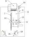
图1为本实用新型的正视剖面结构示意图;Fig. 1 is the front view sectional structure schematic diagram of the utility model;
图2为本实用新型的侧视剖面结构示意图;Fig. 2 is a side view sectional structure schematic diagram of the utility model;
图3为本实用新型的图1中A处放大结构示意图;Fig. 3 is the schematic diagram of enlarged structure at A place in Fig. 1 of the present utility model;
图4为本实用新型的俯视剖面结构示意图。Fig. 4 is a top view sectional structure schematic diagram of the utility model.
图中:1、基座;2、卡座;3、伸缩驱动件;4、推杆;5、驱动杆;6、从动轮;7、加厚开槽刀;8、皮带;9、旋转驱动件;10、主动轮;11、调节板;12、支撑轴;13、铰接座;14、驱动轴;15、护套;16、手柄;17、螺纹杆;18、螺纹套;19、夹持架;20、夹持块。In the figure: 1. Base; 2. Deck; 3. Telescopic drive; 4. Push rod; 5. Drive rod; 6. Driven wheel; 7. Thickened slotting knife; 8. Belt; 10, driving wheel; 11, adjusting plate; 12, support shaft; 13, hinged seat; 14, drive shaft; 15, sheath; 16, handle; 17, threaded rod; 18, threaded sleeve; 19, clamping frame; 20, clamping block.
具体实施方式Detailed ways
下面将结合本实用新型实施例中的附图,对本实用新型实施例中的技术方案进行清楚、完整地描述。基于本实用新型中的实施例,本领域普通技术人员在没有做出创造性劳动前提下所获得的所有其他实施例,都属于本实用新型保护的范围。The following will clearly and completely describe the technical solutions in the embodiments of the present invention with reference to the drawings in the embodiments of the present invention. Based on the embodiments of the present utility model, all other embodiments obtained by persons of ordinary skill in the art without making creative efforts belong to the scope of protection of the present utility model.
请参阅图1-4,本实用新型提供的一种实施例:一种装饰装修用开槽装置,包括基座1和铰接座13,基座1的顶端安装有铰接座13,铰接座13的顶端设有调节板11,调节板11的底端设有支撑轴12,且调节板11通过支撑轴12与铰接座13活动连接,支撑轴12起到活动支撑的作用,调节板11的顶端安装有驱动轴14,驱动轴14的表面套装有护套15,护套15与驱动轴14活动连接,护套15与调节板11固定连接,驱动轴14的外壁上安装有加厚开槽刀7,加厚开槽刀7起到开槽加工的作用,铰接座13一侧的基座1顶端安装有卡座2,卡座2的顶端设有伸缩驱动件3,伸缩驱动件3与卡座2活动连接,伸缩驱动件3的顶端设有推杆4,推杆4起到动力驱动的作用,推杆4的顶端安装有驱动杆5,且驱动杆5与调节板11固定连接,驱动杆5与推杆4活动连接;Please refer to Figures 1-4, an embodiment provided by the utility model: a slotting device for decoration, including a
使用时通过将装饰装修板材放置在基座1的顶端,由两组夹持块20对装饰装修板材进行夹持固定,打开旋转驱动件9,由旋转驱动件9驱动加厚开槽刀7旋转,打开伸缩驱动件3,在基座1的支撑下,在卡座2对伸缩驱动件3的配合下,由伸缩驱动件3驱动推杆4移动,由推杆4驱动驱动杆5往下移动,由驱动杆5带动调节板11转动,铰接座13和支撑轴12配合对调节板11进行限位支撑,由调节板11带动护套15、驱动轴14和加厚开槽刀7进行角度的转动,由加厚开槽刀7自动的转动对装饰装修板材开槽加工,当开槽完成后伸缩驱动件3进行自动的复位,来方便下一工件加工,来加快装饰装修板材开槽的速度,实现了开槽装置对装饰装修板材自动的转动移动开槽加工,方便了开槽装置便捷的转动驱动,提高了开槽装置的加工效率;When in use, by placing the decorative panel on the top of the
驱动轴14表面远离加厚开槽刀7的一端安装有从动轮6,且驱动轴14与从动轮6固定连接,从动轮6一侧的调节板11顶端安装有旋转驱动件9,旋转驱动件9起到动力驱动的作用,旋转驱动件9的输出端安装有主动轮10,主动轮10的表面设有皮带8,且皮带8的一端延伸至从动轮6的表面,皮带8起到动力传动的作用;
使用时通过打开旋转驱动件9,旋转驱动件9驱动主动轮10旋转,由主动轮10驱动皮带8移动,在调节板11的支撑下,在皮带8的传动下驱动从动轮6旋转,由从动轮6驱动驱动轴14转动,护套15对驱动轴14活动支撑,由驱动轴14带动加厚开槽刀7旋转,来提高加厚开槽刀7驱动时的稳定性,实现了开槽装置可靠的传动驱动,提高了开槽装置运行时的稳定性;When in use, by opening the
加厚开槽刀7两侧的基座1顶端皆安装有夹持架19,夹持架19的顶端皆安装有螺纹套18,螺纹套18与夹持架19固定连接,螺纹套18的内部皆设有螺纹杆17,螺纹杆17与螺纹套18螺纹连接,螺纹杆17的顶端皆安装有手柄16,螺纹杆17的底端皆安装有夹持块20,夹持块20与螺纹杆17活动连接,夹持块20与夹持架19滑动连接;The top of the
使用时通过将装饰装修板材放置在基座1的顶端,旋转两组手柄16,手柄16驱动螺纹杆17旋转,在夹持架19的支撑下,在螺纹套18和螺纹杆17的螺纹配合下,螺纹杆17往下移动,由螺纹杆17带动夹持块20往下移动,由两组夹持块20对装饰装修板材进行夹持固定,来加快装饰装修板材装夹的速度,来防止装饰装修板材开槽时发生移动,实现了开槽装置对装饰装修板材快速的夹持固定,加快了开槽装置装夹的速度。When in use, place the decorative plate on the top of the
本申请实施例在使用时:首先通过将装饰装修板材放置在基座1的顶端,由两组夹持块20对装饰装修板材进行夹持固定,打开旋转驱动件9,由旋转驱动件9驱动加厚开槽刀7旋转,打开伸缩驱动件3,在基座1的支撑下,在卡座2对伸缩驱动件3的配合下,由伸缩驱动件3驱动推杆4移动,由推杆4驱动驱动杆5往下移动,由驱动杆5带动调节板11转动,铰接座13和支撑轴12配合对调节板11进行限位支撑,由调节板11带动护套15、驱动轴14和加厚开槽刀7进行角度的转动,由加厚开槽刀7自动的转动对装饰装修板材开槽加工,当开槽完成后伸缩驱动件3进行自动的复位,来方便下一工件加工,来加快装饰装修板材开槽的速度,之后通过打开旋转驱动件9,旋转驱动件9驱动主动轮10旋转,由主动轮10驱动皮带8移动,在调节板11的支撑下,在皮带8的传动下驱动从动轮6旋转,由从动轮6驱动驱动轴14转动,护套15对驱动轴14活动支撑,由驱动轴14带动加厚开槽刀7旋转,来提高加厚开槽刀7驱动时的稳定性,再通过将装饰装修板材放置在基座1的顶端,旋转两组手柄16,手柄16驱动螺纹杆17旋转,在夹持架19的支撑下,在螺纹套18和螺纹杆17的螺纹配合下,螺纹杆17往下移动,由螺纹杆17带动夹持块20往下移动,由两组夹持块20对装饰装修板材进行夹持固定,来加快装饰装修板材装夹的速度,来防止装饰装修板材开槽时发生移动,来完成开槽装置的使用工作。When the embodiment of the present application is in use: firstly, by placing the decorative panel on the top of the
Claims (6)
Priority Applications (1)
| Application Number | Priority Date | Filing Date | Title |
|---|---|---|---|
| CN202221775531.4U CN217775777U (en) | 2022-07-11 | 2022-07-11 | Slotting device for decoration |
Applications Claiming Priority (1)
| Application Number | Priority Date | Filing Date | Title |
|---|---|---|---|
| CN202221775531.4U CN217775777U (en) | 2022-07-11 | 2022-07-11 | Slotting device for decoration |
Publications (1)
| Publication Number | Publication Date |
|---|---|
| CN217775777U true CN217775777U (en) | 2022-11-11 |
Family
ID=83938188
Family Applications (1)
| Application Number | Title | Priority Date | Filing Date |
|---|---|---|---|
| CN202221775531.4U Expired - Fee Related CN217775777U (en) | 2022-07-11 | 2022-07-11 | Slotting device for decoration |
Country Status (1)
| Country | Link |
|---|---|
| CN (1) | CN217775777U (en) |
-
2022
- 2022-07-11 CN CN202221775531.4U patent/CN217775777U/en not_active Expired - Fee Related
Similar Documents
| Publication | Publication Date | Title |
|---|---|---|
| CN215036218U (en) | Stainless steel parts machining is with equipment of polishing convenient to adjust | |
| CN111906546A (en) | Aluminum alloy cutting equipment with burring function | |
| CN217166728U (en) | Automatic special plane of new forms of energy pipe fitting | |
| CN214770394U (en) | Positioning and centering device for high-precision machining machine tool | |
| CN212886699U (en) | Device of stainless steel decorative pipe is polished to multi-angle | |
| CN222154744U (en) | Turnover device for mechanical automatic processing | |
| CN219853963U (en) | Clamping device for machining cylindrical grinding machine | |
| CN220562448U (en) | Engraving machine plate clamping and overturning mechanism | |
| CN218639320U (en) | Automatic continuous peeling machine for agricultural machinery accessory production | |
| CN213106001U (en) | Burr polishing equipment for mechanical casting | |
| CN218611719U (en) | Movable center mechanism | |
| CN214295299U (en) | Fixing clamp for engraving machine convenient for replacing graver | |
| CN217168972U (en) | Automatic nixing pottery fettling device of location | |
| CN114536246B (en) | A quick clamping device for machinery manufacturing | |
| CN218696716U (en) | One-way mandrel surface grinding device convenient to adjust and used for refrigeration equipment | |
| CN218557582U (en) | Stone material processing side cut device | |
| CN211361742U (en) | Grinding disc machine for processing glass products | |
| CN214868847U (en) | Be used for connecting locking lever adds clamping apparatus | |
| CN220515512U (en) | Milling machine convenient to centre gripping | |
| CN212444630U (en) | Automatic grinding machine for machining | |
| CN223071117U (en) | Electric power pole galvanization processing grinding device | |
| CN220296541U (en) | Machine tool group | |
| CN221048242U (en) | Machining fixture for rotary holes in side walls of shells | |
| CN223098163U (en) | Automatic processing equipment for aluminum hanging ring | |
| CN224088615U (en) | A grinding device for processing aluminum single panels |
Legal Events
| Date | Code | Title | Description |
|---|---|---|---|
| GR01 | Patent grant | ||
| GR01 | Patent grant | ||
| CF01 | Termination of patent right due to non-payment of annual fee |
Granted publication date: 20221111 |
|
| CF01 | Termination of patent right due to non-payment of annual fee |