CN217754068U - Slewing bearing steering mechanism - Google Patents
Slewing bearing steering mechanism Download PDFInfo
- Publication number
- CN217754068U CN217754068U CN202221840840.5U CN202221840840U CN217754068U CN 217754068 U CN217754068 U CN 217754068U CN 202221840840 U CN202221840840 U CN 202221840840U CN 217754068 U CN217754068 U CN 217754068U
- Authority
- CN
- China
- Prior art keywords
- bearing
- well
- box
- slewing
- steering
- Prior art date
- Legal status (The legal status is an assumption and is not a legal conclusion. Google has not performed a legal analysis and makes no representation as to the accuracy of the status listed.)
- Active
Links
- 230000005540 biological transmission Effects 0.000 claims abstract description 39
- 241000380131 Ammophila arenaria Species 0.000 claims abstract description 14
- 238000003466 welding Methods 0.000 claims description 2
- 238000000034 method Methods 0.000 abstract description 4
- 239000003921 oil Substances 0.000 description 14
- 230000000694 effects Effects 0.000 description 4
- 238000005461 lubrication Methods 0.000 description 4
- 239000010687 lubricating oil Substances 0.000 description 3
- 230000007774 longterm Effects 0.000 description 2
- 239000000314 lubricant Substances 0.000 description 2
- 230000001050 lubricating effect Effects 0.000 description 2
- 239000013049 sediment Substances 0.000 description 2
- 239000000725 suspension Substances 0.000 description 2
- 230000004075 alteration Effects 0.000 description 1
- 230000009286 beneficial effect Effects 0.000 description 1
- 238000001914 filtration Methods 0.000 description 1
- 238000012986 modification Methods 0.000 description 1
- 230000004048 modification Effects 0.000 description 1
- 238000005507 spraying Methods 0.000 description 1
- 238000006467 substitution reaction Methods 0.000 description 1
Images


Landscapes
- General Details Of Gearings (AREA)
Abstract
The utility model belongs to the technical field of the helm steering technique and specifically relates to a slewing bearing helm steering mechanism, including the generator that is used for beginning the hull helm steering function, be used for being equipped with in the protection and change the well case of device, make the hull go forward the helm steering main part and connect the transmission axle of helm steering main part and well case, its characterized in that: the two sides of the top of the well box are provided with generators, the middle position of the bottom of the well box is provided with a transmission shaft, and one side of the transmission shaft is provided with a steering main body. The utility model discloses a slewing bearing drives the helm steering function when the helm steering uses, and the lubricated problem of friction when having solved the bearing and using.
Description
Technical Field
The utility model relates to a helm steering technical field specifically is a slewing bearing helm steering mechanism.
Background
In the prior art, a slewing bearing steering mechanism usually adopts an external rotation structure, and the external rotation structure can bear small slewing moment and has relatively small self bearing capacity; in addition, in the process of long-term rotation of the supporting rudder, the lubrication effect is poor, and in order to ensure good lubrication effect, the lubricant needs to be added in a manual circulation manner, however, the rudder mechanism is generally fixed behind the ship body and is arranged in a suspension manner, so that the condition of adding the lubricant is severe, the requirement on an operator is high, and the daily care is inconvenient, so that the effect of poor rotation in the use process is caused.
Application number CN201920624337.8 discloses a slewing bearing steering mechanism, which comprises an upper gear box, a transmission shaft and a lower gear box which are linked in sequence, wherein the upper gear box is fixed on an upper support plate; the upper end surface of the top outer ring of the top bearing is fixedly connected with the upper supporting plate, and the top inner ring of the top bearing is provided with top meshing teeth; the linkage sleeve is sleeved on the transmission shaft, and the upper end of the linkage sleeve is fixedly connected with the lower surface of the top inner ring of the top bearing; a linkage gear is sleeved on an output shaft of the driving motor, the driving motor is fixed on the upper support plate, and the linkage gear is meshed with the top meshing teeth; the bottom inner ring of the bottom bearing is fixedly connected with the outer wall of the linkage sleeve; the inner wall of the upper end of the outer cover pipe is fixedly connected with the top bearing, and the inner wall of the lower end of the outer cover pipe is fixedly connected with the bottom outer ring of the bottom bearing; the lubricating part is fixed in a cavity formed between the outer cover pipe and the linkage sleeve pipe and is used for spraying lubricating oil to the top bearing. The slewing bearing steering mechanism is convenient to lubricate and good in slewing effect.
Although the above patent solves the problems of the background art, the above patent still has a problem that the deposit generated inside the oil tank is dropped into the gear to cause a failure after a long time use.
SUMMERY OF THE UTILITY MODEL
In order to achieve the above object, the utility model provides a following technical scheme:
the utility model provides a slewing bearing helm steering mechanism, is equipped with the well case that changes the bearing device including the generator that is used for beginning the hull to turn the rudder and operates, is used for the protection, makes the rudder main part that the hull gos forward and connects the transmission shaft who changes rudder main part and well case, its characterized in that: the double-shaft type elevator is characterized in that generators are arranged on two sides of the top of the well box, a transmission shaft is arranged in the middle of the bottom of the well box, and a steering main body is arranged on one side of the transmission shaft.
As the utility model discloses preferred scheme, the both sides that the bottom is close to transmission axle position in the well case are equipped with the second bearing, two second bearing tops all are equipped with the first bearing that rotates opposite direction, all be equipped with protection box and contact tube on two first bearings, protection box top is equipped with the transmission pipe, the oil tank is connected to the one end that protection box was kept away from to two transmission pipes, the oil tank outside is equipped with the filter screen with transmission pipe hookup location, the inside transmission pipe of oil tank is connected with the suction pump.
As the utility model discloses preferred scheme, the generator bottom links to each other and the hookup location is equipped with the contact tube with the well case, the first bearing is connected to the generator other end at well incasement one end to the contact tube.
As the utility model discloses preferred scheme, one side that the electric conduction pipe was kept away from to the protection box is equipped with the filter screen, the transmission pipe is connected to the filter screen, the filter screen sets up to two-layer, the filter screen passes through welded fastening on oil tank and protection box.
As the preferred scheme of the utility model, the contact tube passes through the screw tightening connection with the generator bottom.
As the utility model discloses preferred scheme, the bottom position is equipped with the third bearing in the transmission axle, the third bearing top is equipped with the fourth bearing that rotates opposite direction.
Compared with the prior art, the beneficial effects of the utility model are that: in order to ensure good lubricating effect, the lubrication is needed to be added in a manual circulation mode, however, the steering mechanism is generally fixed behind a ship body and arranged in a suspension mode, so that the condition for adding the lubrication is harsh, the requirement on operators is high, daily care is inconvenient, poor rotation is caused in the using process, and the problem that the phenomenon that sediment generated inside an oil tank is dropped into a gear to cause failure is caused. This application has adopted filtering component, through set up the filter screen between bearing and transmission pipe and between transmission pipe and the oil tank, makes lubricating oil can be during clean effectual inflow rotary bearing, has solved the long-term problem that leads to the bearing card to pause that uses of rotary bearing.
Drawings
FIG. 1 is a sectional view of the whole structure of the present invention;
FIG. 2 is a perspective view of the protection box on the protection shaft of the present invention;
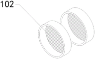
fig. 3 is a perspective view of the filter screen of the present invention.
In the figure: 1. a well box; 101. an oil tank; 102. a filter screen; 103. a suction pump; 104. a conveying pipe; 105. A conductive tube; 106. a first bearing; 107. a second bearing; 108. a protection box; 2. a generator; 3. A steering main body; 4. a transmission shaft; 401. a third bearing; 402. and a fourth bearing.
Detailed Description
The technical solution in the embodiments of the present invention will be clearly and completely described below in conjunction with the embodiments of the present invention, and it is obvious that the described embodiments are only some embodiments of the present invention, rather than all embodiments, and all other embodiments obtained by a person of ordinary skill in the art without creative work belong to the scope of the present invention based on the embodiments of the present invention.
In order to facilitate understanding of the present invention, the present invention will be described more fully hereinafter with reference to the accompanying drawings. Several embodiments of the present invention are presented. The invention may, however, be embodied in many different forms and should not be construed as limited to the embodiments set forth herein. Rather, these embodiments are provided so that this disclosure will be thorough and complete.
It will be understood that when an element is referred to as being "secured to" another element, it can be directly on the other element or intervening elements may also be present. When an element is referred to as being "connected" to another element, it can be directly connected to the other element or intervening elements may also be present. The terms "vertical," "horizontal," "left," "right," and the like as used herein are for illustrative purposes only.
Unless defined otherwise, all technical and scientific terms used herein have the same meaning as commonly understood by one of ordinary skill in the art to which this invention belongs. The terminology used in the description of the invention herein is for the purpose of describing particular embodiments only and is not intended to be limiting of the invention. As used herein, the term "and/or" includes any and all combinations of one or more of the associated listed items.
Referring to fig. 1-3, the device comprises a generator 2 for starting the operation of steering the ship, a well box 1 for protecting the inside of which a steering device is arranged, a steering body 3 for advancing the ship, and a transmission shaft 4 for connecting the steering body 3 and the well box 1, and is characterized in that: the two sides of the top of the well box 1 are provided with generators 2, the middle position of the bottom of the well box 1 is provided with a transmission shaft 4, and one side of the transmission shaft 4 is provided with a steering main body 3.
In an embodiment, referring to fig. 1, second bearings 107 are disposed on two sides of a bottom portion in the well box 1 near the transmission shaft 4, first bearings 106 with opposite rotation directions are disposed at top ends of the two second bearings 107, a protection box 108 and a conductive pipe 105 are disposed on each of the two first bearings 106, a transmission pipe 104 is disposed at a top end of the protection box 108, one end of each transmission pipe 104, which is far away from the protection box 108, is connected to the oil tank 101, a filter screen 102 is disposed at a connection position between the outside of the oil tank 101 and the transmission pipe 104, the transmission pipe 104 inside the oil tank 101 is connected to a suction pump 103, the bottom portion of the generator 2 is connected to the well box 1, the connection position is provided with the conductive pipe 105, and one end of the conductive pipe 105 in the well box 1 is connected to the generator 2, and the other end of the conductive pipe 105 is connected to the first bearings 106. The conductive tube 105 is screwed with the bottom of the generator 2, and the filter screen 102 is fixed on the oil tank 101 and the protection box 108 by welding.
In an embodiment, referring to fig. 2-3, a filter screen 102 is disposed on a side of the protection box 108 away from the conductive tube 105, the filter screen 102 is connected to the transmission tube 104, and the filter screen 102 is disposed in two layers.
In an embodiment, referring to fig. 1, a third bearing 401 is disposed at a bottom position in the transmission shaft 4, and a fourth bearing 402 with an opposite rotation direction is disposed at a top end of the third bearing 401.
The utility model discloses work flow: when the oil-saving steering device is used, through the operation of the generator 2, the electric conduction pipe 105 connects the generator 2 with the first bearing 106 and the fourth bearing 402, the first bearing 106 and the fourth bearing 402 rotate and drive the gear and the second bearing 107 and the third bearing 401 which are opposite to each other and have larger bearing force to rotate, so that the steering main body 3 is driven to swing left and right, lubricating oil is more effectively dripped between the bearings through the filter screen 102 arranged between the suction pump 103 and the oil tank 101 and the filter screen 102 arranged between the transmission pipe 104 and the protection box 108, and the problems of gear blockage and poor steering rotation caused by the fact that oil tank sediments enter the bearings are reduced.
Although embodiments of the present invention have been shown and described, it will be appreciated by those skilled in the art that changes, modifications, substitutions and alterations can be made in these embodiments without departing from the principles and spirit of the invention, the scope of which is defined in the appended claims and their equivalents.
Claims (6)
1. The utility model provides a slewing bearing helm steering mechanism, is including being used for beginning generator (2) that the hull helm steering was operated, well case (1) that are used for being equipped with the helm steering device in the protection, steering main part (3) that make the hull go forward and transmission axle (4) of connecting helm steering main part (3) and well case (1), its characterized in that: the steering device is characterized in that the two sides of the top of the well box (1) are respectively provided with a generator (2), the middle position of the bottom of the well box (1) is provided with a transmission shaft (4), and one side of the transmission shaft (4) is provided with a steering main body (3).
2. A slewing rudder mechanism according to claim 1, characterised in that: the well case (1) is characterized in that second bearings (107) are arranged on two sides of the bottom of the well case close to the position of the transmission shaft (4), first bearings (106) with opposite rotating directions are arranged at the top ends of the second bearings (107), a protection box (108) and a conductive pipe (105) are arranged on the first bearings (106), a transmission pipe (104) is arranged at the top end of the protection box (108), one end, far away from the protection box (108), of the two transmission pipes (104) is connected with the oil tank (101), a filter screen (102) is arranged at the connecting position of the outer portion of the oil tank (101) and the transmission pipe (104), and the transmission pipe (104) inside the oil tank (101) is connected with a suction pump (103).
3. A slewing rudder mechanism according to claim 1, characterised in that: the bottom of the generator (2) is connected with the well box (1) and a conductive tube (105) is arranged at the connection position, one end of the conductive tube (105) in the well box (1) is connected with the other end of the generator (2) and is connected with a first bearing (106).
4. A slewing rudder mechanism according to claim 2, characterised in that: one side, far away from the conductive pipe (105), of the protection box (108) is provided with a filter screen (102), the filter screen (102) is connected with a transmission pipe (104), the filter screen (102) is arranged into two layers, and the filter screen (102) is fixed on the oil tank (101) and the protection box (108) through welding.
5. A slewing rudder mechanism according to claim 3, characterised in that: the conductive tube (105) is connected with the bottom of the generator (2) through screws in a screwing mode.
6. A slewing rudder mechanism according to claim 1, characterised in that: the bottom position in transmission shaft (4) is equipped with third bearing (401), third bearing (401) top is equipped with fourth bearing (402) that the direction of rotation is opposite.
Priority Applications (1)
| Application Number | Priority Date | Filing Date | Title |
|---|---|---|---|
| CN202221840840.5U CN217754068U (en) | 2022-07-15 | 2022-07-15 | Slewing bearing steering mechanism |
Applications Claiming Priority (1)
| Application Number | Priority Date | Filing Date | Title |
|---|---|---|---|
| CN202221840840.5U CN217754068U (en) | 2022-07-15 | 2022-07-15 | Slewing bearing steering mechanism |
Publications (1)
| Publication Number | Publication Date |
|---|---|
| CN217754068U true CN217754068U (en) | 2022-11-08 |
Family
ID=83874267
Family Applications (1)
| Application Number | Title | Priority Date | Filing Date |
|---|---|---|---|
| CN202221840840.5U Active CN217754068U (en) | 2022-07-15 | 2022-07-15 | Slewing bearing steering mechanism |
Country Status (1)
| Country | Link |
|---|---|
| CN (1) | CN217754068U (en) |
-
2022
- 2022-07-15 CN CN202221840840.5U patent/CN217754068U/en active Active
Similar Documents
| Publication | Publication Date | Title |
|---|---|---|
| CN209065326U (en) | High-speed and high-efficiency elevator | |
| JPH0738760Y2 (en) | Lubricating structure of speed reducer using helical gears | |
| CN112112947B (en) | Multi-input high-bearing-capacity vertical transmission device and lubricating method thereof | |
| CN111483752B (en) | Intelligent material handling equipment in workshop | |
| CN211951388U (en) | A multi-shaft output reducer | |
| CN108286603A (en) | Excavator upper transmission | |
| CN211659422U (en) | Filter for galvanization convenient to clearance | |
| CN218935235U (en) | Speed reducer with lubrication assembly | |
| CN208041103U (en) | A kind of marine gearbox | |
| CN217633773U (en) | Intelligent speed reducer | |
| CN116518060A (en) | High-load driving and decelerating mechanism | |
| CN215410060U (en) | Wear-resistant gear speed reducer with high lubricating quality | |
| CN211975842U (en) | Splash lubrication type worm gear speed reducer | |
| CN222880299U (en) | Novel two-stage speed reducer for beam pumping unit | |
| JPH01254486A (en) | Drive unit lubricating device for inboard outboard engine | |
| CN222615931U (en) | Herringbone transmission gear structure of yacht gear box | |
| CN209511014U (en) | A kind of Self-lubricating gear case | |
| CN222687230U (en) | A reducer for industrial robots | |
| CN107268545B (en) | A kind of closed gate hoist | |
| CN216056671U (en) | Feeding transmission mechanism of speed reducer direct transmission screw nut | |
| CN209164491U (en) | A kind of helical gear-bevel gear three-level transmission speed reducer | |
| CN213064504U (en) | Speed change integrated box | |
| CN217583050U (en) | Built-in planetary gear box of 3K structure type | |
| CN216045322U (en) | Dustproof gear speed reducer | |
| JPH086716Y2 (en) | Lubricating oil idle pump for speed reducer / reverse gear for ships |
Legal Events
| Date | Code | Title | Description |
|---|---|---|---|
| GR01 | Patent grant | ||
| GR01 | Patent grant |