CN217737845U - Environment-friendly energy-saving air flow drying heat exchange device - Google Patents
Environment-friendly energy-saving air flow drying heat exchange device Download PDFInfo
- Publication number
- CN217737845U CN217737845U CN202221886460.5U CN202221886460U CN217737845U CN 217737845 U CN217737845 U CN 217737845U CN 202221886460 U CN202221886460 U CN 202221886460U CN 217737845 U CN217737845 U CN 217737845U
- Authority
- CN
- China
- Prior art keywords
- air
- tower
- energy
- hot
- heat
- Prior art date
- Legal status (The legal status is an assumption and is not a legal conclusion. Google has not performed a legal analysis and makes no representation as to the accuracy of the status listed.)
- Active
Links
- 238000001035 drying Methods 0.000 title claims abstract description 15
- 230000007613 environmental effect Effects 0.000 claims abstract description 14
- 239000000463 material Substances 0.000 claims abstract description 11
- 238000012546 transfer Methods 0.000 claims abstract description 9
- 238000000926 separation method Methods 0.000 claims abstract description 3
- 230000001877 deodorizing effect Effects 0.000 claims description 10
- 238000004064 recycling Methods 0.000 claims description 3
- 238000004332 deodorization Methods 0.000 claims 3
- 238000004519 manufacturing process Methods 0.000 abstract description 9
- 238000003912 environmental pollution Methods 0.000 abstract description 7
- 238000005265 energy consumption Methods 0.000 abstract description 6
- 239000000796 flavoring agent Substances 0.000 abstract description 6
- 235000019634 flavors Nutrition 0.000 abstract description 6
- 239000002699 waste material Substances 0.000 abstract description 5
- 238000012545 processing Methods 0.000 abstract description 2
- 238000000034 method Methods 0.000 description 7
- 230000008569 process Effects 0.000 description 6
- 238000010521 absorption reaction Methods 0.000 description 4
- 230000006872 improvement Effects 0.000 description 4
- 125000004122 cyclic group Chemical group 0.000 description 2
- 238000010438 heat treatment Methods 0.000 description 2
- 235000019633 pungent taste Nutrition 0.000 description 2
- 238000005406 washing Methods 0.000 description 2
- 206010022998 Irritability Diseases 0.000 description 1
- 230000009471 action Effects 0.000 description 1
- 238000007792 addition Methods 0.000 description 1
- 238000007664 blowing Methods 0.000 description 1
- 238000013461 design Methods 0.000 description 1
- 238000007599 discharging Methods 0.000 description 1
- 239000012535 impurity Substances 0.000 description 1
- 238000012986 modification Methods 0.000 description 1
- 230000004048 modification Effects 0.000 description 1
- 239000002918 waste heat Substances 0.000 description 1
Images

Landscapes
- Drying Of Solid Materials (AREA)
Abstract
The utility model discloses an air current stoving heat transfer device of environmental protection and energy saving belongs to processing equipment technical field, including the forced draught blower of introducing fresh air, the heater that heats fresh air, smash and dry host computer wet material, the separator that separates is carried out to the material after the drying, blow the pulse machine that looses mutually to the light after the separation, with hot-blast exhaust draught fan, the afterbody at the draught fan is provided with the heat exchanger that is linked together through pipeline and forced draught blower, the one-level that is provided with on the upper portion of heat exchanger and gets rid of the smell removes the flavor tower, the second grade that is provided with on the upper portion of one-level and gets rid of the flavor tower removes the flavor tower. This practicality can reduce the energy consumption with heat energy recycle, environmental protection, in guaranteeing high efficiency serialization production process, can effectively reduce the energy waste, solves environmental pollution's problem.
Description
Technical Field
The utility model belongs to the technical field of the processing equipment technique and specifically relates to an air current stoving heat transfer device of environmental protection and energy saving.
Background
The existing pulse airflow dryer uses a blower to introduce air, and the air is heated by a heater to form hot airflow. The wet material is crushed by the main machine and then flows along with the hot air flow, so that the heated area of the material is increased and the drying process is accelerated; the dried material is separated by a separator, then the heavy phase sinks and is collected, the light phase enters a pulse machine to be blown away, the product is stuck on a pulse bag and is shaken off and collected by compressed air, and hot air is discharged along with a draught fan. Has the advantages of large drying strength, high automation degree and complete equipment supply.
The amount of steam consumed for heating cold air to reach the temperature required by the process is large, and if the product has a relatively pungent taste in the production process, the cold air can be discharged into the air along with hot air sent by the draught fan to cause environmental pollution, and heat energy in the hot air can be lost to cause energy waste.
Therefore, it is necessary to develop an environment-friendly and energy-saving airflow drying heat exchange device.
SUMMERY OF THE UTILITY MODEL
The utility model discloses the technical problem that needs to solve provides the air current stoving heat transfer device of environmental protection and energy saving, can with the heat energy recycle in the pulse airflow stoving process flow, get rid of the smell in the product, the environmental protection reduces the energy consumption, can effectively reduce the energy waste guaranteeing high efficiency serialization production process, solves environmental pollution's problem.
In order to solve the technical problem, the utility model discloses the technical scheme who adopts is:
the utility model provides an air current stoving heat transfer device of environmental protection and energy saving, including the forced draught blower that introduces fresh air, the heater that heats fresh air, smash and dry host computer wet material, the separator that separates the material after the drying, blow the pulse machine that looses mutually to the light after the separation, with hot-blast exhaust draught fan, the afterbody at the draught fan is provided with the heat exchanger that is linked together through pipeline and forced draught blower, the one-level that is provided with on the upper portion of heat exchanger and gets rid of the smell removes the flavor tower, the upper portion that removes the flavor tower at the one-level is provided with the second grade that gets rid of the smell tower.
The utility model discloses technical scheme's further improvement lies in: an exhaust pipeline connected with the primary deodorizing tower, a heat exchange chain, a hot air cylinder for temporarily storing heated fresh air, a hot air channel for communicating the hot air cylinder with an air inlet of a blower, and a blower opening connected with an air outlet of the blower and used for introducing fresh air are arranged in the heat exchanger; the heat exchange chain can heat hot air exhausted by the draught fan to heat fresh air from the air feeder.
The utility model discloses technical scheme's further improvement lies in: essence for absorbing smell is arranged in the first-stage smell removing tower and the second-stage smell removing tower.
The utility model discloses technical scheme's further improvement lies in: and the essence in the first-stage smell removing tower is discharged after being absorbed, and the essence in the second-stage smell removing tower is led into the first-stage smell removing tower for recycling after being absorbed.
The utility model discloses technical scheme's further improvement lies in: the pipeline comprises a fresh air channel which is connected with an air supply outlet of the air supply machine and is filled with fresh air, and a hot air channel which is connected with an air inlet of the air supply machine and is used for returning hot air, wherein the hot air channel is provided with a hot air cylinder.
Due to the adoption of the technical scheme, the utility model discloses the technological progress who gains is:
1. the utility model discloses increase the heat in the heat transfer device replacement hot-blast behind the draught fan, the forced draught blower passes through the pipeline and is connected with the heat exchanger, the fresh air that comes from the forced draught blower gets into the forced draught blower air inlet after absorbing the hot-blast heat of draught fan exhaust, the waste heat that utilizes the exhaust hot-blast preheats the fresh air of forced draught blower, the cyclic utilization of heat energy is realized to the mode that adopts the higher heat exchanger replacement air temperature of heat utilization ratio under the circumstances of guaranteeing production efficiency, the effectual energy loss that has reduced, the production cost is saved, resource utilization rate is improved.
2. The utility model discloses increase behind the heat exchanger and remove the flavor tower and absorb irritability smell in the exhaust hot-blast, the effectual environmental pollution that has reduced has reached the environmental standard requirement.
3. The utility model discloses simple structure, simple to operate, easy to carry out, the effectual environmental protection and energy saving theory of will be carried through to the production process.
Drawings
FIG. 1 is a schematic view of the overall structure of the present invention;
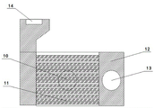
FIG. 2 is a schematic view of the internal structure of the heat exchanger of the present invention;
the device comprises a blower 1, a heater 2, a heater 3, a main machine 4, a separator 5, a pulse machine 6, an induced draft fan 7, a heat exchanger 8, a primary deodorizing tower 9, a secondary deodorizing tower 10, an exhaust pipeline 11, a heat exchange chain 12, a hot air cylinder 13, a hot air channel 14, a blower port 15 and a fresh air channel.
Detailed Description
The embodiment of the application provides an air current stoving heat transfer device of environmental protection and energy saving, has solved the energy waste and can cause environmental pollution's problem among the prior art, can be with the heat energy recycle in the pulse air current stoving process flow, get rid of the pungent smell in the product, has realized not only environmental protection but also can reduce the energy consumption.
The design idea of the application is as follows: the existing pulse airflow dryer is composed of a blower 1, a heater 2, a host 3, a separator 4, a pulse machine 5, a draught fan 6 and the like, and air moves downwards along the heater 2, the host 3 and the separator 4. In order to reduce energy consumption, a heat exchanger 7 is added behind an induced draft fan 6 to replace heat in hot air, an air feeder 1 is connected with the heat exchanger 7 through a pipeline, and fresh air of the air feeder 1 enters an air inlet of the air feeder 1 after absorbing heat of the hot air exhausted by the induced draft fan 6; in addition, two odor removal towers are additionally arranged behind the heat exchanger 7 to absorb pungent odor in hot air so as to reduce environmental pollution and meet the requirement of environmental protection standard.
It should be noted that, in the description of the present invention, the technical terms "upper", "lower", "front", "back", "left", "right", "longitudinal", "horizontal", "inner", "outer" and the like indicate the direction or the position relationship based on the direction or the position relationship shown in the drawings, and only for the convenience of description and understanding of the technical solution of the present invention, the above description is not limiting to the present invention, the present invention is not limited to the above description, and the changes, modifications, additions or replacements made by the ordinary skilled in the art within the essential scope of the present invention should be regarded as the protection scope of the present invention.
In the description of the present invention, it is to be understood that the terms "center", "longitudinal", "lateral", "length", "width", "thickness", "upper", "lower", "front", "rear", "left", "right", "vertical", "horizontal", "top", "bottom", "inner", "outer", and the like indicate orientations or positional relationships based on those shown in the drawings, and are only for convenience of description and simplicity of description, and do not indicate or imply that the device or element referred to must have a particular orientation, be constructed and operated in a particular orientation, and therefore, should not be construed as limiting the present invention.
The present invention will be described in further detail with reference to the following drawings and embodiments:
as shown in fig. 1, an environment-friendly and energy-saving airflow drying heat exchanger comprises a blower 1 for introducing fresh air, a heater 2 for heating the fresh air, a main machine 3 for crushing and drying wet materials, a separator 4 for separating the dried materials, a pulse machine 5 for blowing away separated light phases, and a draught fan 6 for discharging hot air, wherein a heat exchanger 7 communicated with the blower 1 through a pipeline is arranged at the tail part of the draught fan 6, a primary deodorizing tower 8 for removing odor is arranged at the upper part of the heat exchanger 7, and a secondary deodorizing tower 9 for continuously removing odor is arranged at the upper part of the primary deodorizing tower 8.
Further, as shown in fig. 2, an exhaust duct 10 connected to the primary deodorizing tower 8, a heat exchange chain 11, a hot air cylinder 12 for temporarily storing heated fresh air, a hot air passage 13 for communicating the hot air cylinder 12 with an air inlet of the blower 1, and a blower port 14 connected to an air outlet of the blower 1 and through which fresh air is introduced are provided in the heat exchanger 7; the heat exchange chain 11 exchanges heat with hot air in the draught fan 6 to heat fresh air.
Furthermore, essence for absorbing smell is arranged in the first-stage smell removing tower 8 and the second-stage smell removing tower 9.
Further, the essence in the first-stage smell-removing tower 8 is discharged after the absorption is finished, and the essence in the second-stage smell-removing tower 9 is led into the first-stage smell-removing tower 8 for recycling after the absorption is finished.
Further, the pipeline comprises a fresh air channel 15 which is connected with a blower port 14 of the blower 1 and is filled with fresh air, and a hot air channel 13 which is connected with an air inlet of the blower 1 and is used for returning hot air by the hot air cylinder 12. The blower 1 is provided with an air supply outlet, an air inlet and an air outlet connected with the heater 2.
The working principle is as follows:
fresh air is drawn by an air supply machine pump, enters an air supply machine port 14 through an air supply port and a fresh air channel 15 under the action of a heat exchange chain 11, exchanges hot air (dirty) in an induced draft fan 6 for heat, and heats the fresh air, the heated fresh air temporarily exists in a hot air cylinder 12, and the hot air is sent into an air supply machine 1 through a hot air channel 13, and the sent hot air has a certain temperature, so that the temperature required by the process standard is reached, the steam quantity required by a heater 2 can be reduced, and the workshop production cost is effectively reduced.
Hot air (dirty) flows into the primary deodorizing tower 8 through an exhaust pipeline 10, then flows into the secondary deodorizing tower 9, and is finally discharged; essence which can absorb pungent smell exists in the first-stage smell removal tower 8 and the second-stage smell removal tower 9, most of the pungent smell can be absorbed in the first-stage smell removal tower 8, and exhausted hot air is further purified in the second-stage smell removal tower 9, so that the emission standard is met, and the environment is prevented from being polluted.
The absorption capacity in the second-stage smell removal tower 9 is smaller, so that the essence in the first-stage smell removal tower 8 can be discharged after the absorption is finished, and the essence in the second-stage smell removal tower 9 is guided into the first-stage smell removal tower 8, so that the production efficiency is ensured, and the resources are saved.
In the prior art, when the dryer is selected, hot air can be divided into two parts, one part is sent into the washing tower to remove impurities, and the other part directly enters the hot air furnace for cyclic utilization, so that although energy consumption is saved to a certain extent, the heat loss of the hot air in the washing tower is reduced, and the part entering the hot air furnace can be repeatedly polluted if the hot air furnace has pungent taste. Compared with the process, the process has the advantages of higher heat utilization rate and more environmental friendliness.
To sum up, the utility model provides a one set can reduce the pulse air current drying device of energy consumption with heat energy recycle, environmental protection, in guaranteeing high efficiency serialization production process, can effectively reduce the energy waste, solve environmental pollution's problem.
Claims (5)
1. The utility model provides an energy-conserving air current stoving heat transfer device of environmental protection, includes forced draught blower (1) of introducing fresh air, carries out heater (2) that heat to fresh air, smashes and dry host computer (3) to wet material, carries out separator (4) of separating to the material after the drying, blows pulse machine (5) scattered, draught fan (6) with hot-blast exhaust to the light looks after the separation, its characterized in that: the tail of the draught fan (6) is provided with a heat exchanger (7) communicated with the air feeder (1) through a pipeline, the upper part of the heat exchanger (7) is provided with a primary deodorization tower (8) for removing odor, and the upper part of the primary deodorization tower (8) is provided with a secondary deodorization tower (9) for removing odor.
2. The environment-friendly and energy-saving airflow drying heat exchange device according to claim 1, characterized in that: the heat exchanger (7) is provided with an exhaust pipeline (10) connected with the primary deodorizing tower (8), a heat exchange chain (11), a hot air cylinder (12) for temporarily storing heated fresh air, a hot air channel (13) for communicating the hot air cylinder (12) with an air inlet of the air feeder (1), and an air feeder port (14) which is connected with an air feeding port of the air feeder (1) and is used for introducing the fresh air; heat transfer chain (11) can heat the fresh air that comes from forced draught fan (1) with draught fan (6) exhaust hot-blast heat transfer.
3. The environment-friendly and energy-saving airflow drying heat exchange device according to claim 1, characterized in that: essence for absorbing smell is arranged in the first-stage smell removing tower (8) and the second-stage smell removing tower (9).
4. The environment-friendly and energy-saving airflow drying heat exchange device according to claim 3, characterized in that: the essence in the first-stage smell removing tower (8) is discharged after being absorbed, and the essence in the second-stage smell removing tower (9) is led into the first-stage smell removing tower (8) for recycling after being absorbed.
5. The environment-friendly and energy-saving airflow drying heat exchange device according to claim 1, characterized in that: the pipeline comprises a fresh air channel (15) which is connected with an air supply outlet of the air supply device (1) and an air supply device outlet (14) and is used for introducing fresh air, and a hot air channel (13) which is connected with an air inlet of the air supply device (1) and used for returning hot air, wherein the hot air cylinder (12) is arranged in the hot air channel.
Priority Applications (1)
| Application Number | Priority Date | Filing Date | Title |
|---|---|---|---|
| CN202221886460.5U CN217737845U (en) | 2022-07-22 | 2022-07-22 | Environment-friendly energy-saving air flow drying heat exchange device |
Applications Claiming Priority (1)
| Application Number | Priority Date | Filing Date | Title |
|---|---|---|---|
| CN202221886460.5U CN217737845U (en) | 2022-07-22 | 2022-07-22 | Environment-friendly energy-saving air flow drying heat exchange device |
Publications (1)
| Publication Number | Publication Date |
|---|---|
| CN217737845U true CN217737845U (en) | 2022-11-04 |
Family
ID=83849942
Family Applications (1)
| Application Number | Title | Priority Date | Filing Date |
|---|---|---|---|
| CN202221886460.5U Active CN217737845U (en) | 2022-07-22 | 2022-07-22 | Environment-friendly energy-saving air flow drying heat exchange device |
Country Status (1)
| Country | Link |
|---|---|
| CN (1) | CN217737845U (en) |
-
2022
- 2022-07-22 CN CN202221886460.5U patent/CN217737845U/en active Active
Similar Documents
| Publication | Publication Date | Title |
|---|---|---|
| CN105115283A (en) | Airflow energy-saving drying device and airflow energy-saving drying method | |
| CN102500116B (en) | High-efficiency energy-saving closed circulatory spray drying method and drying system | |
| CN201876064U (en) | Drying machine with hot air circulating system with compressed air filtering top and air drafting bottom | |
| CN102435016B (en) | Method for directly recycling waste gas and waste heat of dryer by utilizing compression heat pump | |
| CN104913613B (en) | Spinning fabric energy-saving dryer | |
| CN205676649U (en) | Dryer exhaust gas processing device | |
| CN104913623B (en) | One kind weaving cloth energy-saving dryer | |
| CN110550847A (en) | Energy-saving heat pump sludge drying system | |
| CN206783979U (en) | A kind of knitted fabric drying and setting machine | |
| CN206176948U (en) | Matter and dry water recycle system are put forward to brown coal drying | |
| CN206056225U (en) | A kind of flash dryer circulation of tail gas application system | |
| CN210463769U (en) | Heat source recycling device | |
| CN209816553U (en) | Recycling device for papermaking drying tail gas | |
| CN219314810U (en) | Convection type sludge granulating and drying system | |
| CN211913279U (en) | Hot air temperature recovery device for airflow drying tail gas | |
| CN214168013U (en) | Environment-friendly blast furnace slag treatment steam recovery system | |
| CN217287579U (en) | Pulse dust collector for heating blowing air by using condensed water | |
| CN107843070A (en) | A kind of dehumidifying heat pump | |
| CN216558347U (en) | Sintering grading combined cooling and waste heat recovery device | |
| CN100395500C (en) | Drying process of rubber additives | |
| CN103697673B (en) | Air energy airflow drying equipment | |
| CN209420804U (en) | The dedicated concurrent-mixed flow dryer of big yield efficient quality guaranteeing paddy | |
| CN206724593U (en) | A kind of air circulation recovering mechanism of baking room | |
| CN115143732B (en) | A kind of continuous drying system and continuous drying method for p-nitroaniline | |
| CN218097094U (en) | Light solid material pressing air drying device |
Legal Events
| Date | Code | Title | Description |
|---|---|---|---|
| GR01 | Patent grant | ||
| GR01 | Patent grant |