CN217720418U - Power distribution cabinet assembly with adjustable inner space - Google Patents
Power distribution cabinet assembly with adjustable inner space Download PDFInfo
- Publication number
- CN217720418U CN217720418U CN202220426107.2U CN202220426107U CN217720418U CN 217720418 U CN217720418 U CN 217720418U CN 202220426107 U CN202220426107 U CN 202220426107U CN 217720418 U CN217720418 U CN 217720418U
- Authority
- CN
- China
- Prior art keywords
- box
- inner space
- fixedly arranged
- power distribution
- distribution cabinet
- Prior art date
- Legal status (The legal status is an assumption and is not a legal conclusion. Google has not performed a legal analysis and makes no representation as to the accuracy of the status listed.)
- Active
Links
Images


Abstract
The utility model discloses a switch board subassembly of inner space adjustable, the power distribution box comprises a box body, the box front end rotates through rotating the hinge and is provided with the chamber door, the fixed dry box that is provided with of box inner portion lower extreme, the inside drier that is provided with of dry box, the fixed bottom plate that is provided with in dry box upper end, bottom plate upper end four corners department is fixed all to be provided with the slide bar, four the slide bar front end is fixed to be provided with a plurality of locating holes, four slide on the slide bar and be provided with two and place the board, box one side is fixed and is provided with a plurality of first vents. The utility model discloses a switch board subassembly of inner space adjustable places the board and slides on four slide bars through the spout, twists the screw rod screw thread inside the locating hole again, fixes placing the board, makes the device realize adjusting its inner space, has improved the device's practicality.
Description
Technical Field
The utility model relates to a switch board technical field especially relates to an inner space adjustable switch board subassembly.
Background
The power distribution cabinet has the advantages of small volume, simplicity and convenience in installation, special technical performance, fixed position, unique configuration function, no limitation of places, relatively common application, stability and reliability in operation, high space utilization rate, small occupied area and environmental protection effect, is a control center for reasonably distributing electric energy for various components in a command power supply circuit, is a control link for reliably receiving an upper end power supply and correctly feeding out load electric energy, and is also a key for obtaining whether a user is satisfied with power supply quality, but after the conventional power distribution cabinet is assembled, the internal compartment is fixed, and the interlayer space is difficult to be adjusted through secondary disassembly, so that the space utilization rate in the cabinet body is insufficient.
The prior patent (application number: CN 201920962330.7) discloses a power distribution cabinet with adjustable partitions, which comprises a shell, a cabinet door and a tray unit; the casing is including distributing in four support columns of edge, being fixed in the roof at support column top, being fixed in the bottom plate of support column bottom to and fix the curb plate between the support column, the front side opening of bracket component, the cabinet door set up in the opening part of bracket component front side, the tray unit include the tray body with set up in coupling assembling on the tray body, the tray body passes through coupling assembling carries out detachably and is fixed in the inside of casing, the utility model discloses can adjust the height of each layer board in a flexible way, change the regional space size of each layer in a flexible way. However, the device cannot dissipate heat inside the power distribution cabinet, and the practicability of the device is reduced.
SUMMERY OF THE UTILITY MODEL
The utility model aims at solving the shortcoming that exists among the prior art, and the switch board subassembly that provides of an inner space adjustable.
In order to achieve the above purpose, the utility model adopts the following technical scheme: the utility model provides an inner space adjustable switch board subassembly, includes the box, the box front end is provided with the chamber door through rotating the hinge rotation, the fixed dry box that is provided with of box inner portion lower extreme, dry box inside is provided with the drier, the fixed bottom plate that is provided with in upper end, bottom plate upper end four corners department is all fixed and is provided with the slide bar, four the slide bar front end is fixed and is provided with a plurality of locating holes, four slide on the slide bar and be provided with two and place the board, box one side is fixed and is provided with a plurality of first vents, the box is inside to be close to the fixed fan shell that is provided with in first vent department, one side that first vent was kept away from to the box is fixed and is provided with a plurality of second vents, the box is inside to be close to the fixed mounting bracket that is provided with in second vent department.
As a further description of the above technical solution:
supporting legs are fixedly arranged at four corners of the lower end of the box body, and a waterproof cover is fixedly arranged at the upper end of the box body.
As a further description of the above technical solution:
the bottom plate is provided with a plurality of open pores.
As a further description of the above technical solution:
two place the board four corners department and all fixedly be provided with the spout, two place the board and pass through the spout and slide on the slide bar.
As a further description of the above technical solution:
four locating holes which are arranged on the sliding rods and are positioned at the lower ends of the two placing plates are all provided with screw rods in a threaded manner.
As a further description of the above technical solution:
the fan casing is internally and fixedly provided with a fixed rod, the middle part of the fixed rod is fixedly provided with a driving motor, and the output end of the driving motor is fixedly connected with fan blades.
As a further description of the above technical solution:
the inside dust screen that is provided with of mounting bracket.
As a further description of the above technical solution:
rain-proof sheds are fixedly arranged on the two sides of the box body and on the upper ends of the first ventilation opening and the second ventilation opening.
The utility model discloses following beneficial effect has:
1. the utility model provides a switch board subassembly of inner space adjustable places the board and slides on four slide bars through the spout, twists the screw rod screw thread inside the locating hole again, fixes placing the board, makes the device realize adjusting its inner space, has improved the device's practicality.
2. The utility model provides a switch board subassembly of inner space adjustable, the device pass through driving motor and drive the flabellum, and the use of flabellum can dispel the heat to the inside electrical apparatus of box, improves the life of inside electrical apparatus, and through the dust screen, prevent that the dust from entering into inside the box, the further life who improves electrical apparatus simultaneously.
3. The utility model provides a pair of inner space adjustable switch board subassembly places the drier inside the drying box, improves the inside aridity of box, increases the life of inside electrical apparatus.
Drawings
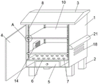
Fig. 1 is a perspective view of a power distribution cabinet assembly with adjustable internal space provided by the present invention;
fig. 2 is a front sectional view of a power distribution cabinet assembly with adjustable internal space provided by the present invention;
FIG. 3 is a schematic view of a placement board structure of a power distribution cabinet assembly with adjustable internal space according to the present invention,
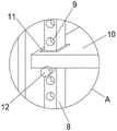
fig. 4 is an enlarged view of a point a in fig. 1.
Illustration of the drawings:
1. a box body; 2. supporting legs; 3. a waterproof cover; 4. a box door; 5. drying the box; 6. a base plate; 7. opening a hole; 8. a slide bar; 9. positioning holes; 10. placing the plate; 11. a chute; 12. a screw; 13. a first vent; 14. a fan case; 15. fixing the rod; 16. a drive motor; 17. a fan blade; 18. a second ventilation opening; 19. a mounting frame; 20. a dust screen; 21. rain-proof canopy.
Detailed Description
The technical solutions in the embodiments of the present invention will be described clearly and completely with reference to the accompanying drawings in the embodiments of the present invention, and it is obvious that the described embodiments are only some embodiments of the present invention, not all embodiments. Based on the embodiments in the present invention, all other embodiments obtained by a person skilled in the art without creative work belong to the protection scope of the present invention.
In the description of the present invention, it should be noted that the terms "center", "upper", "lower", "left", "right", "vertical", "horizontal", "inner", "outer", etc. indicate orientations or positional relationships based on the orientations or positional relationships shown in the drawings, and are only for convenience of description and simplification of the description, but do not indicate or imply that the device or element referred to must have a specific orientation, be constructed and operated in a specific orientation, and thus, should not be construed as limiting the present invention; the terms "first," "second," and "third" are used for descriptive purposes only and are not to be construed as indicating or implying relative importance, and furthermore, unless otherwise explicitly stated or limited, the terms "mounted," "connected," and "connected" are to be construed broadly and may be, for example, fixedly connected, detachably connected, or integrally connected; can be mechanically or electrically connected; they may be connected directly or indirectly through intervening media, or they may be interconnected between two elements. The specific meaning of the above terms in the present invention can be understood in specific cases to those skilled in the art.
Referring to fig. 1-4, the present invention provides an embodiment: a power distribution cabinet assembly with an adjustable internal space comprises a cabinet body 1, wherein a cabinet door 4 is rotatably arranged at the front end of the cabinet body 1 through a rotating hinge, a drying box 5 is fixedly arranged at the lower end inside the cabinet body 1, a drying agent is arranged inside the drying box 5, the dryness inside the cabinet body 1 is improved, a bottom plate 6 is fixedly arranged at the upper end of the drying box 5, slide bars 8 are fixedly arranged at four corners of the upper end of the bottom plate 6, a plurality of positioning holes 9 are fixedly arranged at the front ends of the four slide bars 8, two placing plates 10 are slidably arranged on the four slide bars 8, a plurality of first ventilation openings 13 are fixedly arranged on one side of the cabinet body 1, a fan shell 14 is fixedly arranged inside the cabinet body 1 and close to the first ventilation openings 13, a plurality of second ventilation openings 18 are fixedly arranged on one side of the cabinet body 1 far away from the first ventilation openings 13, and a mounting frame 19 is fixedly arranged inside the cabinet body 1 and close to the second ventilation openings 18;
supporting legs 2 are fixedly arranged at four corners of the lower end of a box body 1, a waterproof cover 3 is fixedly arranged at the upper end of the box body 1, a plurality of holes 7 are formed in a bottom plate 6, sliding grooves 11 are fixedly arranged at four corners of two placing plates 10, the two placing plates 10 slide on the sliding grooves 8 through the sliding grooves 11, screws 12 are arranged on the four sliding rods 8 and located in positioning holes 9 at the lower ends of the two placing plates 10 in a threaded mode, the placing plates 10 slide on the four sliding rods 8 through the sliding grooves 11, the screws 12 are screwed into the positioning holes 9, the placing plates 10 are fixed, the device is enabled to adjust the inner space of the device, fixing rods 15 are fixedly arranged inside a fan shell 14, a driving motor 16 is fixedly arranged in the middle of the fixing rods 15, fan blades 17 are fixedly connected to the output end of the driving motor 16, the fan blades 17 can drive electric appliances inside the box body 1 to dissipate heat through the use of the fan blades 17, a dustproof net mounting frame 20 is fixedly arranged inside the box body 19, rainwater is prevented from entering the box body 1 through the dustproof net 20, dust is prevented from entering the box body 1, and the rain-proof shed 21 is fixedly arranged at the upper ends of the first ventilation opening 13 and the second ventilation opening 18 at the two sides of the box body 1.
The working principle is as follows: when this inner space adjustable switch board subassembly uses, place board 10 and pass through spout 11 and slide on four slide bars 8, twist screw rod 12 screw thread inside locating hole 9 again, fix placing board 10, make the device realize adjusting its inner space, drive flabellum 17 through driving motor 16, the use of flabellum 17 can dispel the heat to the electrical apparatus of box 1 inside, improve the life of inside electrical apparatus, simultaneously through dust screen 20, prevent that the dust from entering into box 1 inside, at the inside drier of placing of 5 dry boxes, improve the inside aridity of box 1.
Finally, it should be noted that: although the present invention has been described in detail with reference to the foregoing embodiments, it will be apparent to those skilled in the art that modifications and variations can be made in the embodiments or in part of the technical features of the embodiments without departing from the spirit and the scope of the invention.
Claims (8)
1. The utility model provides an inner space adjustable switch board subassembly, includes box (1), its characterized in that: the drying box is characterized in that a box door (4) is arranged at the front end of the box body (1) in a rotating mode through a rotating hinge, a drying box (5) is fixedly arranged at the inner lower end of the box body (1), a drying agent is arranged inside the drying box (5), a bottom plate (6) is fixedly arranged at the upper end of the drying box (5), slide bars (8) and four slide bars (8) are fixedly arranged at the four corners of the upper end of the bottom plate (6), a plurality of positioning holes (9) and four slide bars (8) are fixedly arranged at the front end of each slide bar (8), two placing plates (10) are arranged on the slide bars (8) in a sliding mode, a plurality of first ventilation openings (13) are fixedly arranged on one side of the box body (1), a fan shell (14) is fixedly arranged at the position, close to the first ventilation openings (13), of the box body (1), a plurality of second ventilation openings (18) are fixedly arranged at the position, close to the inner portion of the second ventilation openings (18), and a mounting rack (19) is fixedly arranged on the box body (1).
2. The adjustable inner space power distribution cabinet assembly of claim 1, wherein: supporting legs (2) are fixedly arranged at four corners of the lower end of the box body (1), and a waterproof cover (3) is fixedly arranged at the upper end of the box body (1).
3. The power distribution cabinet assembly with the adjustable inner space according to claim 1, wherein: the bottom plate (6) is provided with a plurality of open pores (7).
4. The power distribution cabinet assembly with the adjustable inner space according to claim 1, wherein: the four corners of the two placing plates (10) are fixedly provided with sliding grooves (11), and the two placing plates (10) slide on the sliding rods (8) through the sliding grooves (11).
5. The adjustable inner space power distribution cabinet assembly of claim 1, wherein: screws (12) are arranged on the four sliding rods (8) and in the positioning holes (9) at the lower ends of the two placing plates (10) in a threaded mode.
6. The power distribution cabinet assembly with the adjustable inner space according to claim 1, wherein: the fan casing (14) is internally and fixedly provided with a fixing rod (15), the middle part of the fixing rod (15) is fixedly provided with a driving motor (16), and the output end of the driving motor (16) is fixedly connected with fan blades (17).
7. The adjustable inner space power distribution cabinet assembly of claim 1, wherein: the mounting rack (19) is internally and fixedly provided with a dust screen (20).
8. The adjustable inner space power distribution cabinet assembly of claim 1, wherein: rain-proof sheds (21) are fixedly arranged on the two sides of the box body (1) and at the upper ends of the first ventilation opening (13) and the second ventilation opening (18).
Priority Applications (1)
| Application Number | Priority Date | Filing Date | Title |
|---|---|---|---|
| CN202220426107.2U CN217720418U (en) | 2022-03-01 | 2022-03-01 | Power distribution cabinet assembly with adjustable inner space |
Applications Claiming Priority (1)
| Application Number | Priority Date | Filing Date | Title |
|---|---|---|---|
| CN202220426107.2U CN217720418U (en) | 2022-03-01 | 2022-03-01 | Power distribution cabinet assembly with adjustable inner space |
Publications (1)
| Publication Number | Publication Date |
|---|---|
| CN217720418U true CN217720418U (en) | 2022-11-01 |
Family
ID=83787166
Family Applications (1)
| Application Number | Title | Priority Date | Filing Date |
|---|---|---|---|
| CN202220426107.2U Active CN217720418U (en) | 2022-03-01 | 2022-03-01 | Power distribution cabinet assembly with adjustable inner space |
Country Status (1)
| Country | Link |
|---|---|
| CN (1) | CN217720418U (en) |
-
2022
- 2022-03-01 CN CN202220426107.2U patent/CN217720418U/en active Active
Similar Documents
| Publication | Publication Date | Title |
|---|---|---|
| CN110891386A (en) | Outdoor integrated cabinet for 5G base station | |
| CN207896497U (en) | A kind of power distribution cabinet of good heat dissipation effect | |
| CN211530506U (en) | Novel automatic control power consumption case | |
| CN111182765A (en) | Computer network equipment box that radiating effect is good | |
| CN211930019U (en) | Integrated heat dissipation device for weak current box | |
| CN210201217U (en) | Dampproofing outdoor switch board | |
| CN217720418U (en) | Power distribution cabinet assembly with adjustable inner space | |
| CN211151293U (en) | Intelligent distribution box | |
| CN211860364U (en) | Video monitoring data storage device | |
| CN211958294U (en) | Electric power cabinet with remove dust and heat dissipation | |
| CN212114319U (en) | Power distribution cabinet for power distribution network | |
| CN210803554U (en) | Modularization ammeter case | |
| CN219513629U (en) | Low-voltage cabinet with good heat dissipation performance | |
| CN216672255U (en) | Power distribution cabinet convenient for heat dissipation | |
| CN220273001U (en) | Kitchen switch board with safeguard function | |
| CN219247290U (en) | Switch board with temperature regulation function | |
| CN220358623U (en) | Block terminal protective structure | |
| CN220527427U (en) | Control box of high stability | |
| CN215185404U (en) | Frequency conversion operating mode analysis switch board | |
| CN214896456U (en) | Big data management server | |
| CN216080101U (en) | Automatically controlled box, casing and air conditioner | |
| CN216750792U (en) | Switch board with heat dissipation function | |
| CN213071727U (en) | Low-voltage complete switch equipment | |
| CN214706096U (en) | Mobile high-power supply | |
| CN216648984U (en) | Bidirectional voltage control equipment of low-voltage connection cabinet |
Legal Events
| Date | Code | Title | Description |
|---|---|---|---|
| GR01 | Patent grant | ||
| GR01 | Patent grant |