PCB fixing device convenient to PCB detects
Technical Field
The utility model relates to a PCB board check out test set technical field especially relates to a PCB board fixing device convenient to PCB board detects.
Background
The PCB board is also called as a printed circuit board, and is a provider of electrical connection of electronic components, the PCB board is developed from a single layer to a double-sided board, a multilayer board and a flexible board, and is continuously developed towards high precision, high density and high reliability, the size is continuously reduced, the cost is reduced, and the performance is improved, so that the printed circuit board still keeps strong vitality in the development process of future electronic products, and the development trend of the production and manufacturing technology of the future printed circuit board is towards high density, high precision, fine aperture, fine lead, small space, high reliability, multilayering, high-speed transmission, light weight and thin type in performance.
The PCB board generally needs to utilize check out test set to detect the PCB board after production is accomplished, need install the PCB board on mounting fixture and fix before detecting, but present mounting fixture mostly adopts to compress tightly or the centre gripping is fixed the PCB board at the mode on PCB board surface, this leads to the PCB board surface easily by the anchor clamps scratch, lead to the condition that the PCB board can not be used, and current examine time measuring to two-sided PCB board, probably need carry out twice clamping to the PCB board, it is comparatively troublesome to use, therefore we provide a PCB board fixing device convenient to PCB board detects.
SUMMERY OF THE UTILITY MODEL
The utility model aims at solving and having among the prior art that mounting fixture adopts to compress tightly or the centre gripping is fixed the PCB board at the mode on PCB board surface for the most part, this just leads to the PCB board surface easily by the anchor clamps scratch to and examine time measuring to two-sided PCB board, probably need carry out twice clamping to the PCB board, use comparatively trouble shortcoming, and the PCB board fixing device who is convenient for the PCB board detects that provides.
In order to achieve the above purpose, the utility model adopts the following technical scheme:
a PCB fixing device convenient for PCB detection comprises a detection bottom plate and a test probe, wherein the upper end of the detection bottom plate is fixedly connected with a support frame, and the test probe is arranged on one side of the support frame through a driving assembly;
the upper end fixedly connected with fixed plate of detection bottom plate, the upper end slidable mounting of detection bottom plate has the movable plate, there is driving motor, two sets of one side of fixed plate and movable plate all through motor mounting panel fixed mounting, driving motor is the symmetry setting, and two sets of driving motor are synchronous setting, and is two sets of the equal fixedly connected with fixed block in one side of fixed plate and movable plate is run through respectively to the one end of driving motor output shaft, and is two sets of the inside of fixed block is all rotated and is installed two-way screw rod, and is two sets of equal threaded connection has two sets of clamp splice on the outer wall of two-way screw rod.
Preferably, the driving assembly comprises a cross sliding table, the cross sliding table is fixedly installed on one side of the supporting frame, an electric push rod is fixedly installed on one side of the cross sliding table, and the test probe is arranged at one end of a piston rod of the electric push rod.
Preferably, the upper end of the detection bottom plate is provided with a sliding groove, the lower end of the moving plate is fixedly connected with a sliding block, and the sliding block is arranged inside the sliding groove in a sliding mode.
Preferably, install the screw rod through the bearing rotation on the inner wall of spout, the one end of screw rod runs through the one side of detecting the bottom plate and extends to the outside of detecting the bottom plate, sliding block threaded connection is in the one end of screw rod.
Preferably, two sets of the first groove of dodging and the second groove of dodging have all been seted up to the relative one side of fixed block, and four groups the clamp splice slides respectively and sets up in two sets of first grooves of dodging and two sets of second grooves of dodging, the one end of two-way screw rod is passed through the bearing and is rotated to be connected on the inner wall in the second groove of dodging.
Preferably, two sets of the draw-in groove has all been seted up to one side that the fixed block is relative, and is two sets of the inside of draw-in groove all is provided with the protection and fills up.
Compared with the prior art, the beneficial effects of the utility model are that:
the utility model discloses a fixed plate, the movable plate, the sliding block, the screw rod, two sets of fixed blocks, the protection pad, two-way screw rod and clamp splice isotructure design, according to the PCB plate size rotation screw rod that awaits measuring, be used for adjusting the distance between movable plate and the fixed plate, then tentatively fix the PCB board between two sets of fixed blocks, and the both ends of PCB board joint respectively in the inside of the draw-in groove of seting up on the relative one side of two sets of fixed blocks, through the setting of protection pad, can avoid the both ends of PCB board to be pressed from both sides and hindered, then utilize two-way screw rod to drive two sets of clamp splices and be close to each other or keep away from each other, be used for carrying out centre gripping to the lateral part of PCB board fixedly, do not need anchor clamps to compress tightly or centre gripping on the PCB board surface, avoided the PCB board surface by the condition of anchor clamps scratch;
the utility model discloses a two sets of driving motor that set up in step, when the PCB board is the double sided board, utilize after the survey probe is tested to one side of PCB board, utilize two sets of driving motor that set up in step to drive the PCB board upset 180 after fixing, then recycle and survey the probe and detect to the opposite side of PCB board, need not carry out twice clamping to the PCB board, it is very convenient to use.
Drawings
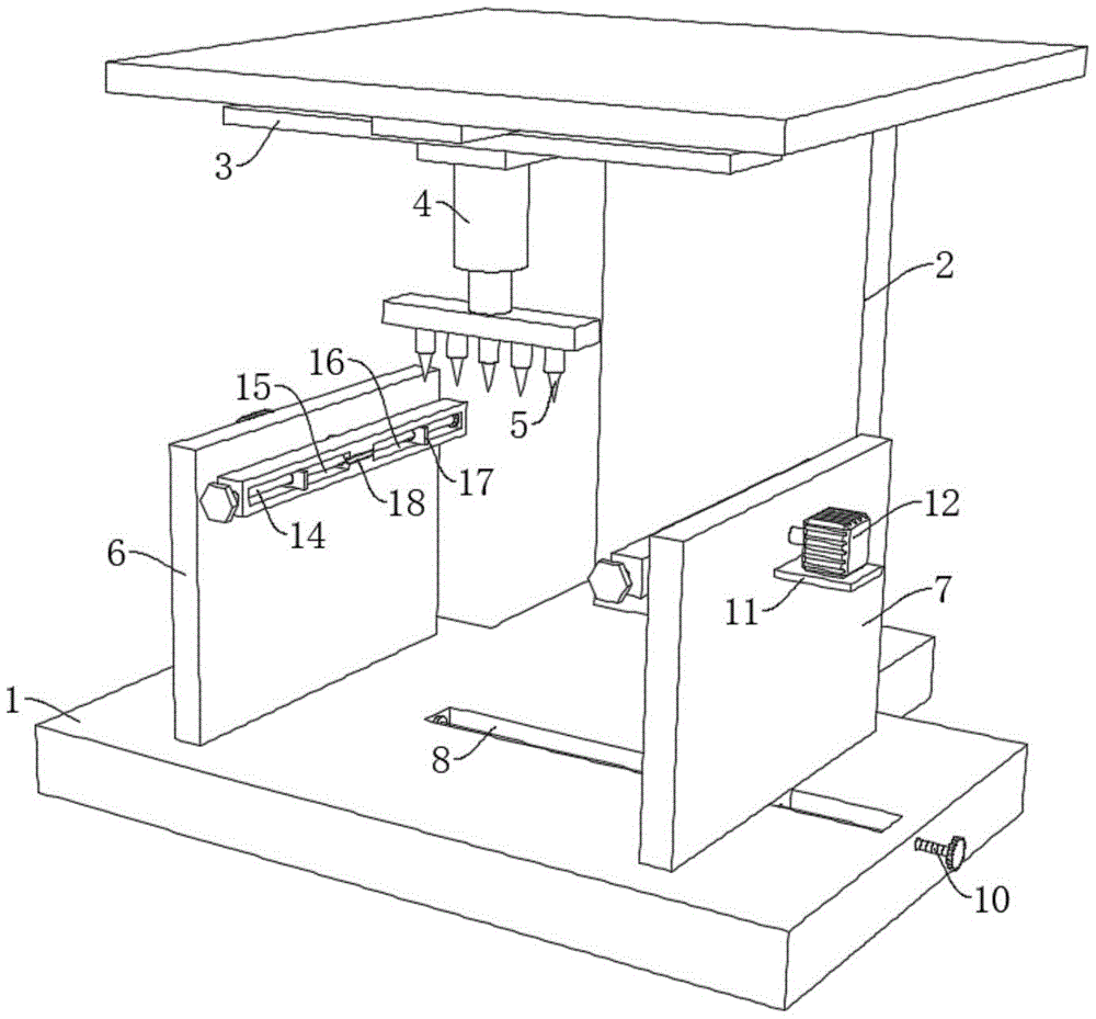
Fig. 1 is a schematic perspective view of a PCB fixing device for facilitating PCB detection according to the present invention;
fig. 2 is a schematic structural view of a front view of a PCB fixing device for facilitating PCB detection according to the present invention;
fig. 3 is the utility model provides a sectional structure schematic diagram of fixed block in PCB board fixing device convenient to PCB board detects.
In the figure: 1. detecting the bottom plate; 2. a support frame; 3. a cross sliding table; 4. an electric push rod; 5. testing the probe; 6. a fixing plate; 7. moving the plate; 8. a chute; 9. a slider; 10. a screw; 11. a motor mounting plate; 12. a drive motor; 13. a fixed block; 14. a bidirectional screw; 15. a first avoidance slot; 16. a second avoidance slot; 17. a clamping block; 18. a protective pad.
Detailed Description
The technical solutions in the embodiments of the present invention will be described clearly and completely with reference to the accompanying drawings in the embodiments of the present invention, and it is obvious that the described embodiments are only some embodiments of the present invention, not all embodiments.
Example one
Referring to fig. 1-3, a PCB fixing device convenient for PCB detection comprises a detection bottom plate 1 and a test probe 5, wherein the upper end of the detection bottom plate 1 is fixedly connected with a support frame 2, the test probe 5 is arranged on one side of the support frame 2 through a driving assembly, and the driving assembly is used for driving the test probe 5 to move for detecting a PCB;
the upper end of the detection bottom plate 1 is fixedly connected with a fixed plate 6, the upper end of the detection bottom plate 1 is slidably provided with a movable plate 7, one sides of the fixed plate 6 and the movable plate 7 are fixedly provided with driving motors 12 through motor mounting plates 11, the two groups of driving motors 12 are symmetrically arranged, the two groups of driving motors 12 are synchronously arranged, one ends of output shafts of the two groups of driving motors 12 respectively penetrate through one sides of the fixed plate 6 and one side of the movable plate 7 and are fixedly connected with fixed blocks 13, two-way screw rods 14 are rotatably arranged inside the two groups of fixed blocks 13, and two groups of clamping blocks 17 are in threaded connection with the outer walls of the two groups of two-way screw rods 14;
through removing movable plate 7 for adjust the distance between movable plate 7 and the fixed plate 6, then fix the PCB board between two sets of fixed blocks 13 preliminarily, then utilize two sets of clamp splice 17 to be close to each other or keep away from, be used for carrying out the centre gripping to the lateral part of PCB board fixed, be convenient for carry out follow-up detection achievement.
Example two
1-3, improve on the basis of embodiment one: a PCB fixing device convenient for PCB detection comprises a detection bottom plate 1 and a test probe 5, wherein the upper end of the detection bottom plate 1 is fixedly connected with a support frame 2, the test probe 5 is arranged on one side of the support frame 2 through a driving assembly, the driving assembly comprises a cross sliding table 3, the cross sliding table 3 is fixedly arranged on one side of the support frame 2, one side of the cross sliding table 3 is fixedly provided with an electric push rod 4, the test probe 5 is arranged at one end of a piston rod of the electric push rod 4, the cross sliding table 3 and the electric push rod 4 are utilized to drive the test probe 5 to move, and the test probe 5 is utilized to test a PCB;
the upper end of the detection bottom plate 1 is fixedly connected with a fixed plate 6, the upper end of the detection bottom plate 1 is slidably provided with a movable plate 7, the upper end of the detection bottom plate 1 is provided with a chute 8, the lower end of the movable plate 7 is fixedly connected with a sliding block 9, the sliding block 9 is slidably arranged in the chute 8, the inner wall of the chute 8 is rotatably provided with a screw rod 10 through a bearing, one end of the screw rod 10 penetrates through one side of the detection bottom plate 1 and extends to the outside of the detection bottom plate 1, the sliding block 9 is in threaded connection with one end of the screw rod 10, and by rotating the screw rod 10, the sliding block 9 can move in the chute 8 due to the threaded fit of the screw rod 10 and the sliding block 9, so that the movable plate 7 is driven to move and the distance between the movable plate 7 and the fixed plate 6 is adjusted;
driving motors 12 are fixedly mounted on one sides of the fixed plate 6 and the movable plate 7 through motor mounting plates 11, the two groups of driving motors 12 are symmetrically arranged, the two groups of driving motors 12 are synchronously arranged, one ends of output shafts of the two groups of driving motors 12 penetrate through one sides of the fixed plate 6 and one side of the movable plate 7 respectively and are fixedly connected with fixed blocks 13, and the PCB can be preliminarily fixed between the two groups of fixed blocks 13 by adjusting the distance between the movable plate 7 and the fixed plate 6;
the opposite sides of the two groups of fixed blocks 13 are provided with clamping grooves, the protecting pads 18 are arranged inside the two groups of clamping grooves, when the PCB is preliminarily fixed between the two groups of fixed blocks 13, the two ends of the PCB are respectively positioned inside the clamping grooves formed in the opposite sides of the two groups of fixed blocks 13, and the two ends of the PCB can be prevented from being clamped and damaged by the arrangement of the protecting pads 18;
the two-way screw rods 14 are rotatably mounted inside the two groups of fixed blocks 13, two groups of clamping blocks 17 are in threaded connection with the outer walls of the two groups of two-way screw rods 14, a first avoidance groove 15 and a second avoidance groove 16 are formed in one opposite side of each of the two groups of fixed blocks 13, the four groups of clamping blocks 17 are respectively arranged inside the two groups of first avoidance grooves 15 and the two groups of second avoidance grooves 16 in a sliding mode, one end of each two-way screw rod 14 is rotatably connected to the inner wall of the second avoidance groove 16 through a bearing, and the two groups of clamping blocks 17 are respectively arranged inside the first avoidance grooves 15 and the second avoidance grooves 16 in a sliding mode through rotation of the two-way screw rods 14 and are in threaded fit with the two-way screw rods 14, so that the two groups of clamping blocks 17 can be close to or far away from each other and are used for clamping and fixing the side portions of the PCB;
when the PCB board is the double-sided board, utilize two sets of synchronous drive motor 12 of setting to drive the PCB board upset 180 after the fixing, then recycle test probe 5 detects the two-sided of PCB board, and it is very convenient to use.
When the utility model is used specifically, firstly, the screw rod 10 is rotated according to the size of the PCB to be detected, and due to the screw rod 10 and the sliding block 9 are in threaded fit, the sliding block 9 can move in the sliding groove 8, so that the movable plate 7 is driven to move, the distance between the movable plate 7 and the fixed plate 6 is adjusted, then the PCB is preliminarily fixed between the two groups of fixed blocks 13, the two ends of the PCB are respectively clamped in the clamping grooves formed on the opposite sides of the two groups of fixed blocks 13, and the two ends of the PCB can be prevented from being damaged by clamping through the arrangement of the protective pad 18;
after the PCB is preliminarily fixed, the bidirectional screw 14 is rotated, and as the two groups of clamping blocks 17 are respectively arranged in the first avoidance groove 15 and the second avoidance groove 16 in a sliding manner and the two groups of clamping blocks 17 are in threaded fit with the bidirectional screw 14, the two groups of clamping blocks 17 can be close to or far away from each other and are used for clamping and fixing the side part of the PCB;
then, the cross sliding table 3 and the electric push rod 4 are started, the cross sliding table 3 and the electric push rod 4 are utilized to drive the test probe 5 to move, and the test probe 5 is utilized to test the PCB;
when the PCB board is the double sided board, utilize test probe 5 to test one side of PCB board after, open two sets of synchronous drive motor 12 that set up, utilize two sets of synchronous drive motor 12 that set up to drive the PCB board upset 180 after the fixing, then recycle test probe 5 and detect the opposite side of PCB board, it is very convenient to use.
However, as is well known to those skilled in the art, the working principle and wiring method of the cross sliding table 3, the electric push rod 4 and the two sets of driving motors 12 are common and are all conventional means or common knowledge, and thus, they will not be described herein again, and those skilled in the art can make any choice according to their needs or convenience.
The above, only be the embodiment of the preferred of the present invention, but the protection scope of the present invention is not limited thereto, and any person skilled in the art is in the technical scope of the present invention, according to the technical solution of the present invention and the utility model, which are designed to be replaced or changed equally, all should be covered within the protection scope of the present invention.