CN217715216U - Energy-saving rotary dehumidifier - Google Patents
Energy-saving rotary dehumidifier Download PDFInfo
- Publication number
- CN217715216U CN217715216U CN202221738087.9U CN202221738087U CN217715216U CN 217715216 U CN217715216 U CN 217715216U CN 202221738087 U CN202221738087 U CN 202221738087U CN 217715216 U CN217715216 U CN 217715216U
- Authority
- CN
- China
- Prior art keywords
- regeneration
- runner
- unit
- dehumidification
- coil
- Prior art date
- Legal status (The legal status is an assumption and is not a legal conclusion. Google has not performed a legal analysis and makes no representation as to the accuracy of the status listed.)
- Active
Links
- 230000008929 regeneration Effects 0.000 claims abstract description 103
- 238000011069 regeneration method Methods 0.000 claims abstract description 103
- 238000007791 dehumidification Methods 0.000 claims abstract description 44
- 238000011084 recovery Methods 0.000 claims abstract description 30
- 238000005485 electric heating Methods 0.000 claims abstract description 9
- 230000001172 regenerating effect Effects 0.000 claims description 15
- 238000007789 sealing Methods 0.000 claims description 8
- 238000009413 insulation Methods 0.000 claims description 5
- 238000009434 installation Methods 0.000 claims description 4
- 230000000694 effects Effects 0.000 abstract description 4
- 239000002918 waste heat Substances 0.000 abstract description 4
- 238000004064 recycling Methods 0.000 abstract 1
- 238000001179 sorption measurement Methods 0.000 description 5
- XLYOFNOQVPJJNP-UHFFFAOYSA-N water Substances O XLYOFNOQVPJJNP-UHFFFAOYSA-N 0.000 description 4
- 239000000463 material Substances 0.000 description 3
- 208000021760 high fever Diseases 0.000 description 2
- 238000010521 absorption reaction Methods 0.000 description 1
- 230000009286 beneficial effect Effects 0.000 description 1
- 230000005540 biological transmission Effects 0.000 description 1
- 230000008094 contradictory effect Effects 0.000 description 1
- 238000003795 desorption Methods 0.000 description 1
- 238000005516 engineering process Methods 0.000 description 1
- 238000010438 heat treatment Methods 0.000 description 1
- 239000007788 liquid Substances 0.000 description 1
- 238000000034 method Methods 0.000 description 1
- 229920006395 saturated elastomer Polymers 0.000 description 1
- 239000002699 waste material Substances 0.000 description 1
Images


Classifications
-
- Y—GENERAL TAGGING OF NEW TECHNOLOGICAL DEVELOPMENTS; GENERAL TAGGING OF CROSS-SECTIONAL TECHNOLOGIES SPANNING OVER SEVERAL SECTIONS OF THE IPC; TECHNICAL SUBJECTS COVERED BY FORMER USPC CROSS-REFERENCE ART COLLECTIONS [XRACs] AND DIGESTS
- Y02—TECHNOLOGIES OR APPLICATIONS FOR MITIGATION OR ADAPTATION AGAINST CLIMATE CHANGE
- Y02B—CLIMATE CHANGE MITIGATION TECHNOLOGIES RELATED TO BUILDINGS, e.g. HOUSING, HOUSE APPLIANCES OR RELATED END-USER APPLICATIONS
- Y02B30/00—Energy efficient heating, ventilation or air conditioning [HVAC]
- Y02B30/56—Heat recovery units
Landscapes
- Drying Of Gases (AREA)
Abstract
The utility model provides an energy-saving rotary dehumidifier, including quick-witted case body, quick-witted case body contains new trend air inlet unit, elementary dehumidification unit, runner regeneration unit, air supply unit, and wherein, runner regeneration unit is located runner dehumidification unit top, runner regeneration unit includes the regeneration air intake, and the regeneration air inlet preheats the coil pipe, regeneration electric heating box, regeneration air outlet, runner dehumidification unit includes runner and drive runner pivoted motor, and the runner includes dehumidification district and regeneration area, and the dehumidification district is located the runner lower part, and the regeneration area is located runner upper portion, the regeneration wind export sets up the heat recovery coil pipe, the heat recovery coil pipe preheats the coil pipe intercommunication with the regeneration air inlet. The waste heat of high heat generated wind passing through the regeneration air outlet is absorbed by the heat recovery coil pipe and is converted into regenerated inlet wind for preheating, so that the waste heat can be effectively absorbed for recycling, and good energy-saving and emission-reducing effects can be achieved.
Description
Technical Field
The utility model relates to a dehumidifier field especially relates to an energy-saving rotary dehumidifier.
Background
The dehumidifier is also called a dehumidifier, a dryer and a dehumidifier, and generally can be divided into two major categories of a household dehumidifier and an industrial dehumidifier, and generally, the dehumidifier is composed of a compressor, a heat exchanger, a fan, a water container, a casing and a controller. The working principle is as follows: the wet air is pumped into the machine by a fan and passes through a heat exchanger, water molecules in the air are condensed into water drops, the treated dry air is discharged out of the machine, and the indoor humidity is kept at the proper relative humidity by circulation. The industrial dehumidifier has high requirement on humidity control, the rotary dehumidifier is one of the most widely applied dehumidification technologies in actual industrial dehumidification, and the rotary dehumidifier utilizes the good hydrophilicity of an adsorption material to adsorb water in air and reduce the humidity of the air. The rotary dehumidifier is composed of a dehumidifying rotary wheel, a transmission device, a fan, a filter, a regeneration heater and the like.
The level of dehumidification efficiency of the rotating wheel is influenced by the adsorption performance of the adsorption material and the regeneration heating part. At present, the main mode of the dehumidification regeneration of the rotating wheel is to blow high-temperature air towards a regeneration area of the rotating wheel, the high temperature enables the moisture adsorption saturated adsorption material to generate moisture desorption, and the high-temperature air is cooled and carries the desorbed moisture to be discharged. The air discharged along with the moisture has higher temperature, can not be effectively utilized, and causes energy waste.
Disclosure of Invention
The utility model aims at providing an energy-saving rotary dehumidifier aims at solving the current rotary dehumidifier runner regeneration process and directly gets rid of high temperature air, causes the extravagant technical problem of the energy.
For realizing above-mentioned purpose, the utility model provides an energy-saving rotary dehumidifier, including machine case body, machine case body contains new trend air inlet unit, elementary dehumidification unit, runner regeneration unit, air supply unit, and wherein, runner regeneration unit is located runner dehumidification unit top, runner regeneration unit includes the regeneration air intake, and regeneration air inlet preheats the coil pipe, regeneration electric heating cabinet, regeneration air outlet, runner dehumidification unit includes runner and drive runner pivoted motor, and the runner includes dehumidification district and regeneration district, and the dehumidification district is located the runner lower part, and the regeneration district is located runner upper portion, regeneration air outlet sets up the heat recovery coil pipe, the heat recovery coil pipe preheats the coil pipe intercommunication with the regeneration air inlet.
Optionally, regeneration electric heating cabinet passes through the regeneration zone of leading-in runner dehumidification unit of regeneration air inlet through the inner flange to by the back air inlet of runner dehumidification unit, by the positive air-out of runner dehumidification unit, runner dehumidification unit openly communicates regeneration air outlet, and regeneration air outlet sets up the fan of airing exhaust, the heat recovery coil pipe is located regeneration air outlet's air-out passageway, and the heat recovery coil pipe is located under the regeneration air inlet preheating coil pipe.
Optionally, the heat recovery coil and the regeneration air inlet preheating coil are the same heat exchange coil, the heat exchange coil is divided into a preheating part and a heat recovery part by a heat insulation sealing plate, the regeneration air outlet is located under the regeneration air inlet, and a heat exchange coil installation channel is arranged between the regeneration air outlet and the regeneration air inlet.
Optionally, the heat-insulating sealing plate includes a coil mounting hole and a flange clamped with the heat exchange coil mounting passage.
Optionally, the tube wall of the heat exchange coil is fixedly connected with heat exchange fins.
Optionally, the regeneration air outlet is connected with a regeneration fan.
Optionally, the bottom of the chassis body is fixedly connected with the base.
Optionally, the fresh air inlet unit comprises a filter fixed at the front end of the dehumidification unit.
Implement the embodiment of the utility model provides a, following beneficial effect has:
compare with current rotary dehumidifier on the market, the utility model discloses can absorb the waste heat of high fever through the regeneration air outlet at the raw wind through the heat recovery coil pipe, because heat recovery coil pipe preheats the coil pipe intercommunication with the regeneration air inlet, heat flow to regeneration air in the heat recovery coil pipe preheats the coil pipe, regeneration air preheats the coil pipe temperature and risees this moment to give regeneration air inlet with heat transfer through the heat exchange, this structure can effectively absorb the dumped heat and recycle, can reach fine energy saving and emission reduction effect.
Drawings
In order to more clearly illustrate the embodiments of the present invention or the technical solutions in the prior art, the drawings needed to be used in the description of the embodiments or the prior art will be briefly described below, it is obvious that the drawings in the following description are only some embodiments of the present invention, and for those skilled in the art, other drawings can be obtained according to the structures shown in the drawings without creative efforts.
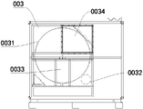
FIG. 1 is a schematic structural view of an energy-saving rotary dehumidifier of the present invention;
FIG. 2 is a schematic view of the dehumidification section of the rotary wheel;
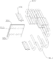
FIG. 3 is a schematic view of a heat exchange coil;
fig. 4 is an exploded view of a heat exchange coil.
Detailed Description
The technical solutions in the embodiments of the present invention will be described clearly and completely with reference to the drawings in the embodiments of the present invention, and it is obvious that the described embodiments are only some embodiments of the present invention, not all embodiments. Based on the embodiments in the present invention, all other embodiments obtained by a person skilled in the art without creative efforts belong to the protection scope of the present invention.
It should be noted that, if the present invention relates to a directional indication (such as up, down, left, right, front, back, 8230 \8230;, 8230;), the directional indication is only used to explain the relative position relationship between the components in a specific posture, the motion situation, etc., and if the specific posture is changed, the directional indication is changed accordingly.
In addition, if there is a description relating to "first", "second", etc. in the embodiments of the present invention, the description of "first", "second", etc. is for descriptive purposes only and is not to be construed as indicating or implying relative importance or implicitly indicating the number of technical features indicated. Thus, a feature defined as "first" or "second" may explicitly or implicitly include at least one of the feature. In addition, if the meaning of "and/or" and/or "appears throughout, the meaning includes three parallel schemes, for example," A and/or B "includes scheme A, or scheme B, or a scheme satisfying both schemes A and B. In addition, the technical solutions in the embodiments may be combined with each other, but it must be based on the realization of those skilled in the art, and when the technical solutions are contradictory or cannot be realized, the combination of the technical solutions should not be considered to exist, and is not within the protection scope of the present invention.
Please refer to fig. 1 to 4, the utility model provides an energy-saving rotary dehumidifier, including chassis body 01, chassis body 01 contains new trend air inlet unit 001, elementary dehumidification unit 002, runner dehumidification unit 003, runner regeneration unit 004, air supply unit 005, and wherein, runner regeneration unit 004 is located runner dehumidification unit 003 top, runner regeneration unit 004 includes regeneration air intake 0041, regeneration air inlet preheating coil 0042, regeneration electric heating case 0043, regeneration air outlet 0044, runner dehumidification unit 003 includes runner 0031 and drive runner 0031 pivoted motor 0032, and runner 0031 includes dehumidification district 0033 and regeneration district 0034, and dehumidification district 0033 is located runner 0031 lower part, and regeneration district 0034 is located runner 0031 upper portion, regeneration air outlet 0044 sets up heat recovery coil 0045, heat recovery coil 0045 communicates with regeneration air inlet preheating coil 0042.
The two air flows respectively enter a dehumidification area and a regeneration area of the rotating wheel, wherein fresh air sequentially passes through the primary dehumidification unit, the rotating wheel dehumidification unit and the air supply unit from the fresh air inlet unit, and the rotating wheel dehumidification unit is the dehumidification area of the rotating wheel; and the regeneration air enters the rotary wheel regeneration unit through the regeneration air inlet and sequentially passes through the preheating coil, the regeneration electric heating box, the rotary wheel regeneration area, the heat recovery coil and the regeneration air outlet. Compared with the prior rotary dehumidifier on the market, the utility model discloses can absorb the high fever through regeneration air outlet at the waste heat of fresh air through the heat recovery coil pipe, because the heat recovery coil pipe preheats the coil pipe intercommunication with the regeneration air inlet, heat flows the regeneration air in the heat recovery coil pipe and preheats the coil pipe, the regeneration air preheats the coil pipe temperature and risees this moment to give regeneration air inlet with heat transfer through the heat exchange, this structure can effectively absorb the discarded heat and recycle, can reach fine energy saving and emission reduction effect.
In one embodiment, the regenerative electric heating box 0043 guides the regenerative intake air into the regeneration zone 0033 of the wheel dehumidification unit 003 through the inner flange 0047, the intake air is fed from the back side of the wheel dehumidification unit 003, the exhaust air is discharged from the front side of the wheel dehumidification unit 003, the front side of the wheel dehumidification unit 003 is communicated with the regenerative air outlet 0044, the regenerative air outlet 0044 is provided with an exhaust fan 0046, the heat recovery coil 0045 is located in the air outlet channel of the regenerative air outlet 0044, and the heat recovery coil 0045 is located right below the regenerative intake air preheating coil 0042.
The heat recovery coil is positioned under the regenerative air inlet preheating coil, so that the recovered heat can be quickly transferred to the regenerative air inlet, and a better heat recovery and reutilization effect is achieved.
In an embodiment, the heat recovery coil 0045 and the regeneration air inlet preheating coil 0042 are the same heat exchange coil 005, the heat exchange coil is divided into a preheating part 0052 and a heat recovery part 0053 by a heat insulation sealing plate 0051, the regeneration air outlet 0044 is located right below the regeneration air inlet 0041, and a heat exchange coil installation channel 0048 is disposed between the regeneration air outlet 0044 and the regeneration air inlet 0041. Through the direct intercommunication between the heat transfer coil, and the lower part is heated continuously, and the inside liquid of coil is heated and is risen, can form the circulation in the coil, carries out heat absorption and release better.
Preferably, the heat shield seal plates 0051 include coil mounting apertures 0054 and flanges 0055 which snap into heat exchange coil mounting channels 0048. The flange can facilitate the installation of the heat insulation sealing baffle plate, and the sealing performance of the heat insulation sealing baffle plate is improved.
Preferably, the heat exchange fins 006 are fixedly connected to the wall of the heat exchange coil 005. The heat exchange fins can enable the heat exchange coil to recover heat and release heat more quickly.
Preferably, the regeneration air outlet 0044 is connected with a regeneration fan 0046. The suction force generated by the regeneration fan generates negative pressure at the regeneration air outlet, the negative pressure is sequentially transmitted to the rotating wheel regeneration area and the regeneration electric heating box and finally reaches the regeneration air inlet, and air inlet is formed at the regeneration air inlet. The suction mode can effectively control the air inlet time and better discharge the regenerative outlet air with high humidity.
In an embodiment, the bottom of the case body 01 is fixedly connected to the base 02.
Preferably, the fresh air intake unit 001 includes a filter 007 fixed to the front end of the dehumidifying unit 002.
The above is only the optional embodiment of the utility model discloses a not consequently restriction the patent scope of the utility model, all be in the utility model discloses a under the design, utilize the equivalent structure transform that the content of the description and the attached drawing was made, or direct/indirect application all includes in other relevant technical field the utility model discloses a patent protection is within range.
Claims (8)
1. The utility model provides an energy-saving rotary dehumidifier, includes quick-witted case body, and quick-witted case body contains new trend air inlet unit, elementary dehumidification unit, runner regeneration unit, air supply unit, and its characterized in that runner regeneration unit is located runner dehumidification unit top, runner regeneration unit includes the regeneration air intake, and regeneration air inlet preheats the coil pipe, regeneration electric heating box, regeneration air outlet, runner dehumidification unit includes runner and drive runner pivoted motor, and the runner includes dehumidification district and regeneration district, and dehumidification district is located the runner lower part, and the regeneration district is located runner upper portion, regeneration air outlet sets up the heat recovery coil pipe, the heat recovery coil pipe preheats the coil pipe intercommunication with the regeneration air inlet.
2. The energy-saving rotary dehumidifier recited in claim 1, wherein the regenerative electric heating box guides the regenerative inlet air into the regeneration zone of the rotary dehumidification unit through the inner flange, the inlet air is fed from the back side of the rotary dehumidification unit, the outlet air is fed from the front side of the rotary dehumidification unit, the front side of the rotary dehumidification unit is communicated with the regenerative outlet, the regenerative outlet is provided with an exhaust fan, the heat recovery coil is located in the outlet air channel of the regenerative outlet, and the heat recovery coil is located right below the regenerative inlet air preheating coil.
3. The energy-saving rotary dehumidifier recited in claim 2, wherein said heat recovery coil and said regeneration air inlet preheating coil are the same heat exchange coil, said heat exchange coil is divided into a preheating part and a heat recovery part by a heat insulation sealing plate, said regeneration air outlet is located under the regeneration air inlet, and a heat exchange coil installation channel is provided between the regeneration air outlet and the regeneration air inlet.
4. An energy-saving rotary dehumidifier as claimed in claim 3 wherein the heat-insulating sealing plate includes coil mounting holes and flanges for engaging with the heat exchange coil mounting passages.
5. The energy-saving rotary dehumidifier recited in claim 3, wherein heat exchange fins are fixedly connected to the walls of said heat exchange coils.
6. An energy-saving rotary dehumidifier as claimed in claim 2, wherein the regeneration air outlet is connected to a regeneration fan.
7. The energy-saving rotary dehumidifier recited in claim 1, wherein said bottom of said cabinet body is fixedly connected to a base.
8. The energy-saving rotary dehumidifier recited in claim 1, wherein said fresh air intake unit comprises a filter fixed to a front end of the dehumidifier unit.
Priority Applications (1)
| Application Number | Priority Date | Filing Date | Title |
|---|---|---|---|
| CN202221738087.9U CN217715216U (en) | 2022-07-07 | 2022-07-07 | Energy-saving rotary dehumidifier |
Applications Claiming Priority (1)
| Application Number | Priority Date | Filing Date | Title |
|---|---|---|---|
| CN202221738087.9U CN217715216U (en) | 2022-07-07 | 2022-07-07 | Energy-saving rotary dehumidifier |
Publications (1)
| Publication Number | Publication Date |
|---|---|
| CN217715216U true CN217715216U (en) | 2022-11-01 |
Family
ID=83776953
Family Applications (1)
| Application Number | Title | Priority Date | Filing Date |
|---|---|---|---|
| CN202221738087.9U Active CN217715216U (en) | 2022-07-07 | 2022-07-07 | Energy-saving rotary dehumidifier |
Country Status (1)
| Country | Link |
|---|---|
| CN (1) | CN217715216U (en) |
-
2022
- 2022-07-07 CN CN202221738087.9U patent/CN217715216U/en active Active
Similar Documents
| Publication | Publication Date | Title |
|---|---|---|
| CN218521471U (en) | Drying module and washing and drying machine | |
| US9869052B2 (en) | Heat exchanger for condensation in clothes drying and clothes drying system and clothes dryer and drying method thereof | |
| CN212057970U (en) | System device for drying fine dried noodles | |
| CN104913613B (en) | Spinning fabric energy-saving dryer | |
| CN210220227U (en) | Embedded dryer and drying room with secondary waste heat recovery function | |
| CN202427328U (en) | Absorption dryer | |
| CN219674620U (en) | An infrared drying test device based on thermoelectric effect | |
| CN111473614B (en) | Environment-friendly heat pump dryer | |
| CN214198972U (en) | Rotary wheel dehumidification air conditioning unit | |
| CN212670135U (en) | Air hood exhaust treatment system of paper machine | |
| CN211575345U (en) | Energy-saving rotating wheel dehumidifying device | |
| CN214701034U (en) | Lightweight dehumidifier structure | |
| CN212805873U (en) | High-efficient semiconductor dehumidifier | |
| CN115540577A (en) | Air source heat pump backheating energy-saving device and heat pump system thereof | |
| CN210993631U (en) | A flue gas dehydration and white smoke elimination system | |
| CN223036836U (en) | Air duct sealing structure and lithium battery material drying device | |
| CN219775890U (en) | Heat-absorbing energy-saving dehumidifier | |
| CN219328297U (en) | Drying dehumidifier with heat recovery function | |
| CN221258971U (en) | Small-size semiconductor refrigeration energy-saving rotary dehumidifier | |
| CN209840301U (en) | Dehumidifier for automobile lamp production workshop | |
| CN219756915U (en) | Heated air circulation oven | |
| CN214370670U (en) | A cold heat exchanger of an air power unit | |
| CN219322223U (en) | High-efficiency energy-saving generator cabin cooling and dehumidifying device | |
| CN220409941U (en) | Energy-saving environment-friendly heat exchanger for offset press | |
| CN211739341U (en) | High-efficiency heat pipe energy-saving dehumidifier |
Legal Events
| Date | Code | Title | Description |
|---|---|---|---|
| GR01 | Patent grant | ||
| GR01 | Patent grant |