CN217713712U - High-temperature throttle valve - Google Patents
High-temperature throttle valve Download PDFInfo
- Publication number
- CN217713712U CN217713712U CN202123319671.9U CN202123319671U CN217713712U CN 217713712 U CN217713712 U CN 217713712U CN 202123319671 U CN202123319671 U CN 202123319671U CN 217713712 U CN217713712 U CN 217713712U
- Authority
- CN
- China
- Prior art keywords
- valve
- valve rod
- seat
- gap
- pivot
- Prior art date
- Legal status (The legal status is an assumption and is not a legal conclusion. Google has not performed a legal analysis and makes no representation as to the accuracy of the status listed.)
- Active
Links
- 238000007789 sealing Methods 0.000 claims description 25
- 230000003028 elevating effect Effects 0.000 claims description 10
- 239000000428 dust Substances 0.000 claims description 8
- 210000004907 gland Anatomy 0.000 claims description 5
- 239000000945 filler Substances 0.000 claims description 3
- 238000009434 installation Methods 0.000 claims 1
- 230000007246 mechanism Effects 0.000 abstract description 11
- 230000000694 effects Effects 0.000 abstract description 7
- 230000033001 locomotion Effects 0.000 abstract description 7
- 238000012856 packing Methods 0.000 description 21
- 239000012530 fluid Substances 0.000 description 7
- 238000000034 method Methods 0.000 description 7
- 230000001681 protective effect Effects 0.000 description 7
- RYGMFSIKBFXOCR-UHFFFAOYSA-N Copper Chemical compound [Cu] RYGMFSIKBFXOCR-UHFFFAOYSA-N 0.000 description 4
- 229910052802 copper Inorganic materials 0.000 description 4
- 239000010949 copper Substances 0.000 description 4
- 230000008569 process Effects 0.000 description 4
- 230000009471 action Effects 0.000 description 3
- 230000005540 biological transmission Effects 0.000 description 3
- 239000000243 solution Substances 0.000 description 3
- 239000000463 material Substances 0.000 description 2
- 230000009286 beneficial effect Effects 0.000 description 1
- 230000008859 change Effects 0.000 description 1
- 230000007547 defect Effects 0.000 description 1
- 230000008676 import Effects 0.000 description 1
- 238000002347 injection Methods 0.000 description 1
- 239000007924 injection Substances 0.000 description 1
- 238000012423 maintenance Methods 0.000 description 1
- 230000002035 prolonged effect Effects 0.000 description 1
Images

Landscapes
- Indication Of The Valve Opening Or Closing Status (AREA)
Abstract
The invention relates to the technical field of throttle valves and discloses a high-temperature throttle valve which comprises a valve body, wherein a throttle mechanism is arranged in the valve body, the throttle mechanism comprises an outer sliding sleeve and a valve seat, a valve cover is arranged on the upper portion of the valve body, a valve rod is arranged in the valve cover, a valve rod lifting mechanism is arranged on the upper portion of the valve cover, the valve rod lifting mechanism is connected with the valve rod, and an opening indicator is arranged on the valve rod lifting mechanism. This high temperature choke valve drives the valve rod up-and-down motion through valve rod hoist mechanism, and the valve rod drives outer sliding sleeve up-and-down motion. Meanwhile, the valve rod lifting mechanism drives the indicating sleeve of the opening indicator to move up and down, so that the effect of displaying the throttle opening is achieved.
Description
Technical Field
The utility model relates to a choke valve technical field specifically is a high temperature choke valve.
Background
The throttle valve is a valve for controlling a fluid flow by changing a throttle section or a throttle length, and has been widely used in the oil exploitation industry. At present, the existing throttle valve for oil exploitation in the market mostly has the defects of unreliable valve seat seal and valve rod seal and incapability of adapting to high-temperature exploitation environment, and the valve rod seal is not easy to detect and replace after leakage, so that the maintenance difficulty is increased.
SUMMERY OF THE UTILITY MODEL
An object of the utility model is to provide a high temperature choke valve to solve the problem that proposes in the above-mentioned background art.
In order to achieve the above object, the utility model provides a following technical scheme: the utility model provides a high temperature throttle valve, includes the valve body, the left side fixed mounting of valve body has the relief valve, the inside fixed mounting of valve body has the disk seat, the valve gap is installed to the top of valve body, the valve body with be equipped with the backing ring between the valve gap, the top fixed mounting of valve gap has valve rod elevating system, opening indicator is installed on valve rod elevating system upper portion, valve rod elevating system is connected with the valve rod, valve rod lower part fixed mounting has the outer sliding sleeve, the valve rod with install the valve rod packing between the valve gap.
The valve rod lifting mechanism comprises a rotating shaft, a thrust bearing is installed on the rotating shaft from top to bottom, a bearing seat is fixedly installed outside the rotating shaft, a hand wheel is installed on the rotating shaft in a placing mode, a round nut is arranged below the rotating shaft, a valve rod rotation stopping pressing cover is arranged below the round nut, and the rotating shaft is connected with the valve rod through threaded transmission.
Preferably, the indicating mechanism comprises a protective cover, the protective cover is fixedly arranged above the rotating shaft, an indicating sleeve is arranged above the protective cover, and the indicating sleeve is fixedly arranged on the upper portion of the valve rod and follows up along with the up-and-down movement of the valve rod. The outside of the indicating sleeve is provided with scales, so that the opening degree of the throttle valve can be known through scale display.
Preferably, the two sides of the backing ring are clamped by the valve body and the valve cover, the valve body and the valve cover are fixedly installed by the bolt and the nut, and the backing ring is clamped by the valve body and the valve cover to ensure sealing.
Preferably, the valve body internally mounted has the disk seat, the disk seat includes the disk seat body, disk seat body fixed mounting is inside the valve body, the disk seat sealing washer is installed to disk seat body periphery, disk seat body internally mounted has the disk seat bush, the disk seat body with be equipped with the disk seat bush sealing washer between the disk seat bush. The valve seat sealing ring and the valve seat lining sealing ring can ensure the sealing performance of the valve seat at high temperature.
Preferably, valve rod packing is installed on the upper portion of the valve cover, a copper gasket is installed on the upper portion of the valve rod packing, and the valve rod penetrates through the middle of the valve rod packing and the copper gasket. The valve rod packing is far away from high-temperature fluid of the valve cavity, so that the sealing reliability under the high-temperature working condition is ensured. Compared with the prior art, the utility model provides a high temperature choke valve possesses following beneficial effect:
1. the high-temperature throttle valve enables fluid to enter the valve cavity through the inlet, throttles through the outer sliding sleeve and the valve seat, and then enters other pipelines through the outlet, so that the throttling effect is achieved.
2. The rotating shaft is rotated by the hand wheel, the valve rod is driven by the thread pair to move up and down in the rotating shaft, the size of the throttling aperture is adjusted by adjusting the stroke of the up-and-down movement of the outer sliding sleeve, and therefore the throttling adjustable effect is achieved.
3. The valve rod packing contacts with valve rod, valve gap respectively, forms sealedly, realizes the sealed effect of valve rod, and the valve rod packing sets up in the valve gap top, can make the valve rod packing keep away from valve pocket high temperature fluid through the mode that makes the extension of valve gap neck, and the top is arranged in to the valve rod packing, also can realize the change of valve rod packing under the condition of not dismantling the valve gap to increase the sealed reliability and the maintainability of valve rod packing.
4. The square sealing ring is adopted for sealing between the valve seat and the valve body, and the material of the sealing ring has higher adaptability to temperature, so that the high-temperature resistance of the valve seat sealing is ensured.
Drawings
In order to more clearly illustrate the technical solutions in the embodiments of the present invention, the drawings needed to be used in the description of the embodiments are briefly introduced below, and it is obvious that the drawings in the following description are only some embodiments of the present invention, and for those skilled in the art, other drawings can be obtained according to the drawings without inventive labor:
FIG. 1 is a schematic cross-sectional view of the front structure of the present invention;
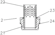
FIG. 2 is a schematic cross-sectional front view of the valve seat of the present invention;
in the figure: 1. a valve body; 2. a valve seat; 21. a valve seat body; 22. a valve seat liner; 23. a bushing seal ring; 24. a valve seat sealing ring; 3. a pressure relief valve; 4. a backing ring; 5. a valve cover; 6. valve stem packing; 7. A valve stem lifting mechanism; 70. a rotating shaft; 71. a hand wheel; 72. a round nut; 73. a rotation stopping gland; 74. Locking the screw; 75. a first dust ring; 76. a bearing seat; 77. an oil injection nozzle; 78. a thrust bearing; 8. an opening degree indicator; 80. a shield; 81. an indicating sleeve; 82. a second dust retaining ring; 83. a third dust ring;
Detailed Description
The technical solutions in the embodiments of the present invention will be described clearly and completely with reference to the accompanying drawings in the embodiments of the present invention, and it is obvious that the described embodiments are only some embodiments of the present invention, not all embodiments. Based on the embodiments in the present invention, all other embodiments obtained by a person skilled in the art without creative efforts all belong to the protection scope of the present invention.
In the present invention, unless otherwise expressly stated or limited, the terms "mounted," "connected," and "fixed" are to be construed broadly and may, for example, be fixedly connected, detachably connected, or integrally formed; can be mechanically or electrically connected; either directly or indirectly through intervening media, either internally or in any other relationship. The specific meanings of the above terms in the present invention can be understood by those skilled in the art according to specific situations.
Referring to fig. 1-2, the present invention provides a technical solution: the utility model provides a high temperature choke valve, includes valve body 1, the left side fixed mounting relief valve 3 of valve body 1, the upper portion fixed mounting of valve body 1 has valve gap 5, be provided with backing ring 4 between valve body 1 and the valve gap 5, disk seat 2 is installed to 1 inside below of valve body, valve rod elevating system 7 is installed to 5 tops of valve gap, aperture indicator 8 is installed to 7 tops of valve rod elevating system, valve rod elevating system intermediate junction has valve rod 9, valve rod below fixed mounting outer sliding sleeve 10, install valve rod filler 6 between valve rod 9 and the valve gap 5.
In this embodiment, the both sides of backing ring 4 are pressed from both sides tightly through valve body 1 and valve gap 5, and valve body 1 and valve gap 5 pass through bolt and nut fixed mounting, press from both sides tight backing ring through valve body 1 and valve gap 5 and guarantee sealedly.
It should be noted that a copper gasket is installed on the upper portion of the valve rod packing 6, and the valve rod 9 passes through the middle of the valve rod packing 6 and the copper gasket. The valve rod packing 6 is far away from high-temperature fluid of the valve cavity, so that the sealing reliability under the high-temperature working condition is ensured.
The valve rod lifting mechanism 7 comprises a rotating shaft 70, thrust bearings 78 are installed on the upper portion and the lower portion of the rotating shaft 70, a bearing seat 76 is installed on the outer portion of the rotating shaft, the bearing seat 76 is fixedly installed on the valve cover 5, an oil filling nozzle 77 is arranged on one side of the bearing seat 76, a locking screw 74 is arranged on the other side of the bearing seat, a first dust ring 75 is installed between the bearing seat 76 and the rotating shaft 70, a hand wheel 71 is installed on the upper portion of the rotating shaft 70, a round nut 72 is arranged below the rotating shaft 70, the round nut 72 is fixedly installed on the valve cover 5, and a rotation stopping gland 73 is installed below the round nut 73.
In the present embodiment, the rotating shaft 70 is in threaded transmission connection with the valve rod 9.
The opening indicator 8 comprises a protective cover 80 installed on the rotating shaft 70 and used for fixing the hand wheel 71, an indicating sleeve 81 is arranged in the protective cover 80, the indicating sleeve 81 is fixedly installed on the valve rod 9, a second dust retaining ring 82 is arranged between the protective cover 80 and the indicating sleeve 81, and a third dust retaining ring 83 is arranged between the indicating sleeve 81 and the valve rod 9.
In this embodiment, the indicating sleeve 81 is fixedly installed on the upper portion of the valve stem 9 and follows up the up-and-down movement of the valve stem 9.
Note that, the indication sleeve 81 has a scale on the outside thereof, and the opening degree of the throttle valve is displayed by the scale.
The valve seat 2 comprises a valve seat body 21, a valve seat lining 22 is arranged inside the valve seat body 21, a lining sealing ring 23 is arranged between the valve seat body 21 and the valve seat lining 22, and a valve seat sealing ring 24 is arranged outside the valve seat body 21.
In this embodiment, the seat seal ring 24 and the seat liner seal ring 23 can ensure the seat sealing performance at high temperature.
In the practical operation process, when the throttling valve is used, the hand wheel 71 is rotated to drive the rotating shaft 70 to rotate, the rotating shaft 70 and the valve rod 9 are transmitted through the thread pair, so that the valve rod 9 moves up and down, the valve rod 9 drives the outer sliding sleeve 10 to move up and down, the contact area between the outer sliding sleeve and the valve seat bushing 22 is increased or reduced, and the throttling function of the throttling valve is realized. The valve rod 9 drives the indicating sleeve 81 to move up and down, scales are marked on the outer portion of the indicating sleeve 81, the top end plane of the protective cover 80 is used as a pointer, and the scales are used for indicating the opening degree of the throttle valve.
The high-temperature throttle valve of this embodiment makes fluid get into the valve pocket through the import, and after outer sliding sleeve and disk seat throttle, get into other pipelines from the export to reach the effect of throttle, rotate the pivot through the hand wheel moreover, the pivot is by screw thread pair transmission valve rod, and the valve rod drives outer sliding sleeve up-and-down motion, adjusts the size in throttle aperture through the stroke of adjusting outer sliding sleeve up-and-down motion, thereby reaches throttle adjustable effect.
In addition, the valve rod packing of the high-temperature throttling valve of the embodiment is respectively contacted with the valve rod and the valve cover to form sealing, the sealing effect of the valve rod is achieved, the valve rod packing is arranged above the valve cover, the valve rod packing is far away from high-temperature fluid in the valve cavity in a mode that the neck of the valve cover is prolonged, the valve rod packing is arranged above the valve cover, and replacement of the valve rod packing can be achieved under the condition that the valve cover is not detached, so that the sealing reliability and the maintainability of the valve rod packing are improved. And the square sealing ring is adopted between the valve seat and the valve body for sealing, and the material of the sealing ring has higher adaptability to temperature, so that the high-temperature resistance of the valve seat sealing is ensured.
It should be noted that, in this document, relational terms such as first and second, and the like are used solely to distinguish one entity or action from another entity or action without necessarily requiring or implying any actual such relationship or order between such entities or actions. Also, the terms "comprises," "comprising," or any other variation thereof, are intended to cover a non-exclusive inclusion, such that a process, method, article, or apparatus that comprises a list of elements does not include only those elements but may include other elements not expressly listed or inherent to such process, method, article, or apparatus. The term "comprising", without further limitation, means that the element so defined is not excluded from the group consisting of additional identical elements in the process, method, article, or apparatus that comprises the element.
Claims (4)
1. A high temperature throttle valve, includes valve body (1), its characterized in that: the left side fixed mounting of valve body (1) has relief valve (3), the top fixed mounting of valve body (1) has valve gap (5), valve body (1) with install backing ring (4) between valve gap (5), valve rod elevating system (7) are installed to valve gap (5) top, aperture indicator (8) are installed to valve rod elevating system (7) top, valve rod elevating system (7) intermediate junction has valve rod (9), valve gap (5) with install valve rod filler (6) between valve rod (9), valve rod (9) below is connected with outer sliding sleeve (10), valve body (1) internally mounted has disk seat (2).
2. A high-temperature throttle valve according to claim 1, characterized in that: valve rod elevating system (7) are including pivot (70), thrust bearing (78) are respectively installed from top to bottom in pivot (70), the pivot externally mounted has bearing frame (76) to fix pivot (70) on valve gap (5), bearing frame (76) are provided with oiling mouth (77), and the opposite side is provided with locking screw (74), hand wheel (71) is installed to pivot (70) top, valve gap (5) top is installed and is only changeed gland (73) in order to be used for restricting the rotation of valve rod (9) and the reciprocating of valve rod filler (6), only changeing gland (73) top and installing round nut (72) and be used for only changeing gland (73) and fix on valve gap (5).
3. A high-temperature throttle valve according to claim 2, characterized in that: opening indicator (8) are including guard shield (80), guard shield (80) fixed mounting be in on pivot (70) for fixed hand wheel (71), cover (81) is instructed in installation above valve rod (9), valve rod (9) with it sets up third dust ring (83) to instruct between cover (81), guard shield (80) with it sets up second dust ring (82) to instruct between cover (81).
4. A high-temperature throttle valve according to claim 1, characterized in that: the valve seat (2) comprises a valve seat body (21), a valve seat lining (22) is installed inside the valve seat body (21), a lining sealing ring (23) is arranged between the valve seat body (21) and the valve seat lining (22), a valve seat sealing ring (24) is installed on an outer groove of the valve seat body (21), and a valve seat seal is formed between the valve body (1).
Priority Applications (1)
| Application Number | Priority Date | Filing Date | Title |
|---|---|---|---|
| CN202123319671.9U CN217713712U (en) | 2021-12-27 | 2021-12-27 | High-temperature throttle valve |
Applications Claiming Priority (1)
| Application Number | Priority Date | Filing Date | Title |
|---|---|---|---|
| CN202123319671.9U CN217713712U (en) | 2021-12-27 | 2021-12-27 | High-temperature throttle valve |
Publications (1)
| Publication Number | Publication Date |
|---|---|
| CN217713712U true CN217713712U (en) | 2022-11-01 |
Family
ID=83772313
Family Applications (1)
| Application Number | Title | Priority Date | Filing Date |
|---|---|---|---|
| CN202123319671.9U Active CN217713712U (en) | 2021-12-27 | 2021-12-27 | High-temperature throttle valve |
Country Status (1)
| Country | Link |
|---|---|
| CN (1) | CN217713712U (en) |
-
2021
- 2021-12-27 CN CN202123319671.9U patent/CN217713712U/en active Active
Similar Documents
| Publication | Publication Date | Title |
|---|---|---|
| CN209213068U (en) | A kind of water power ball valve automatically cleaning valve seat | |
| CN201348040Y (en) | Adjustable self-compensation shaft sealing mechanism | |
| CN208268435U (en) | A kind of mobile butterfly plate low temperature butterfly valve of self-sealing | |
| CN212718270U (en) | Integral type stop valve | |
| CN207064692U (en) | A kind of improved rising stem (RS.) wedge action valve copper sheathing | |
| CN114776878B (en) | Stainless steel multifunctional front valve | |
| CN207161745U (en) | Flanged gate valve peculiar to vessel | |
| CN216812901U (en) | High-temperature bidirectional metal hard sealing butterfly valve | |
| CN204961891U (en) | Zero friction ball valve sealed firmly | |
| CN214466208U (en) | Gate valve | |
| CN2752552Y (en) | Flat rotary filling seal valve | |
| CN201521670U (en) | Clamp type medium-pressure knife gate valve | |
| CN214500219U (en) | Sealing structure for valve shaft of butterfly valve | |
| CN202867900U (en) | Two-way omni-seal gate valve | |
| CN209909212U (en) | Lubricating and oil sealing device for industrial plunger bottom valve | |
| CN221423904U (en) | High-temperature molten salt butterfly valve | |
| CN108547956B (en) | Self-sealing movable butterfly plate low-temperature butterfly valve | |
| CN205278401U (en) | High temperature resistant triple offset butterfly valve | |
| CN213039937U (en) | Stainless steel valve sealing device | |
| CN222746613U (en) | Cryogenic Butterfly Valve | |
| CN222067723U (en) | High-pressure-resistant small valve | |
| CN222458391U (en) | High-performance double-eccentric elastic metal seal butterfly valve | |
| CN218266582U (en) | Multi-sealing material ejection cylinder of screw press | |
| CN220706425U (en) | High-frequency butterfly valve | |
| CN219712355U (en) | All-metal hard sealing butterfly valve |
Legal Events
| Date | Code | Title | Description |
|---|---|---|---|
| GR01 | Patent grant | ||
| GR01 | Patent grant |