CN217711729U - An Assemblable Primary Structure Hole Reservation Device - Google Patents
An Assemblable Primary Structure Hole Reservation Device Download PDFInfo
- Publication number
- CN217711729U CN217711729U CN202122002829.3U CN202122002829U CN217711729U CN 217711729 U CN217711729 U CN 217711729U CN 202122002829 U CN202122002829 U CN 202122002829U CN 217711729 U CN217711729 U CN 217711729U
- Authority
- CN
- China
- Prior art keywords
- groove
- assembly plate
- wall
- connecting column
- primary structure
- Prior art date
- Legal status (The legal status is an assumption and is not a legal conclusion. Google has not performed a legal analysis and makes no representation as to the accuracy of the status listed.)
- Expired - Fee Related
Links
Images


Landscapes
- Tents Or Canopies (AREA)
Abstract
本实用新型公开了一种可装配的一次结构洞口预留装置,包括装配板,装配板一侧的外壁上设置有凸块,且装配板的顶部开设有凹槽,凸块底部的外壁上焊接有连接柱,且连接柱的内部滑动插接有伸缩柱,凹槽底部的内部上开设有连接槽,连接柱和伸缩柱插接在连接槽的内部,连接柱两侧的外壁上均开设有活动槽,且活动槽的内部滑动连接有活动块。本实用新型装配板为100mm或200mm的统一宽度的标准节,较为标准化,可以根据洞口预留尺寸要求对装配板进行拼装,或长或短,随意加装或拆卸,同时在采用此装置进行洞口预留时,用户不需要将结构板筋进行切割,大大提高项目安全系数,为保护众人安全和创建安全文明工地提供了一大亮点。
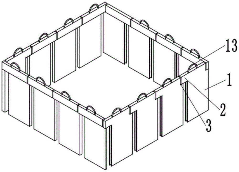
The utility model discloses an assembleable primary structure hole reservation device, which comprises an assembly plate, an outer wall of one side of the assembly plate is provided with a bump, and the top of the assembly plate is provided with a groove, and the outer wall of the bottom of the bump is welded on the outer wall There is a connecting column, and a telescopic column is slidably inserted into the interior of the connecting column, a connecting groove is opened on the inside of the bottom of the groove, the connecting column and the telescopic column are inserted into the interior of the connecting groove, and the outer walls on both sides of the connecting column are provided with The movable groove is slidably connected with a movable block inside the movable groove. The assembly plate of the utility model is a standard section with a uniform width of 100mm or 200mm, which is relatively standardized. The assembly plate can be assembled according to the requirements of the reserved size of the opening, which can be long or short, and can be installed or disassembled at will. When reserved, the user does not need to cut the structural slab, which greatly improves the safety factor of the project, and provides a bright spot for protecting the safety of everyone and creating a safe and civilized construction site.
Description
技术领域technical field
本实用新型涉及洞口预留装置技术领域,尤其涉及一种可装配的一次结构洞口预留装置。The utility model relates to the technical field of hole reservation devices, in particular to an assembleable primary structure hole reservation device.
背景技术Background technique
在科技高速发展、技术创新不断进步的21世纪,装配式引起了世界各方的关注,建筑行业也兴起了装配式的热潮,全国建筑市场和建筑企业依托数字化、信息化的软件和平台,结构工程、建筑工程、机电安装工程的施工过程中都展现出了装配式高效建造、精益建造、智能化建造等特点,尤其是机电工程,机电安装工业化、工厂化、智能化已经是大势所趋,在机电工程的初始阶段,机电预埋管线、套管和洞口伴随着一次结构浇筑进行施工,而为了使套管预埋定位准确,并且便于后期吊装管道,往往会将管井内成排立管的套管在一次结构浇筑时以洞口的形式进行预留,后期再进行套管安装和洞口封。In the 21st century, with the rapid development of science and technology and continuous progress of technological innovation, assembly has attracted the attention of all parties in the world, and the construction industry has also emerged an upsurge of assembly. The national construction market and construction enterprises rely on digital and information software and platforms. The construction process of engineering, construction engineering, and electromechanical installation projects all show the characteristics of prefabricated efficient construction, lean construction, and intelligent construction, especially in electromechanical engineering. In the initial stage of the project, the mechanical and electrical pre-embedded pipelines, casings and openings are constructed along with a structural pouring. In order to make the casing pre-embedded and positioned accurately, and to facilitate the later lifting of the pipeline, the casings of the rows of standpipes in the tube well are often placed It is reserved in the form of a hole when pouring a structure, and then the casing is installed and the hole is sealed later.
传统的洞口预留方式是需要将板面钢筋平铺或者绑扎完毕之后,根据洞口尺寸需要,利用切割机将洞口区域的钢筋切除,然后进行洞口预留及绑扎固定,当遇到较大尺寸洞口时,水电班组不仅需要把洞口区域的钢筋切除和洞口固定,还得利用钢筋废料在洞口区域进行再次绑扎加固,满足洞口周围结构受力的设计要求;此外,当模板拆除之后,较大结构洞口需要在洞口一周设置安全栅栏进行安全防护,因此,亟需设计一种可装配的一次结构洞口预留装置来解决上述问题。The traditional hole reservation method is to flatten or bind the steel bars on the slab surface, use a cutting machine to cut off the steel bars in the hole area according to the size of the hole, and then reserve the hole and tie it up. At the same time, the hydropower team not only needs to remove the steel bars in the opening area and fix the opening, but also needs to use steel bar waste to bind and reinforce the opening area again to meet the design requirements of the structural force around the opening; in addition, when the formwork is removed, the large structural opening It is necessary to set up a safety fence around the hole for safety protection. Therefore, it is urgent to design an assembleable primary structure hole reservation device to solve the above problems.
实用新型内容Utility model content
本实用新型的目的是为了解决现有技术中存在洞口需要在钢筋平铺或者绑扎后再进行切割,然后再对洞口进行固定以及还需对洞口设置安全栅栏进行防护的缺点,而提出的一种可装配的一次结构洞口预留装置。The purpose of this utility model is to solve the shortcomings in the prior art that the hole needs to be cut after the steel bars are tiled or tied, and then the hole is fixed and the hole needs to be protected by a safety fence. Ready-to-assemble primary structural openings.
为了实现上述目的,本实用新型采用了如下技术方案:In order to achieve the above object, the utility model adopts the following technical solutions:
一种可装配的一次结构洞口预留装置,包括装配板,所述装配板一侧的外壁上设置有凸块,且装配板的顶部开设有凹槽,所述凸块底部的外壁上焊接有连接柱,且连接柱的内部滑动插接有伸缩柱,所述凹槽底部的内部上开设有连接槽,所述连接柱和伸缩柱插接在连接槽的内部。An assemblable primary structure hole reservation device, comprising an assembly plate, a protrusion is provided on the outer wall of one side of the assembly plate, and a groove is opened on the top of the assembly plate, and a groove is welded on the outer wall of the bottom of the protrusion. The connecting column is slidably plugged with a telescopic column inside the connecting column, and a connecting groove is opened on the inside of the bottom of the groove, and the connecting column and the telescopic column are inserted into the connecting groove.
进一步的,所述连接柱两侧的外壁上均开设有活动槽,且活动槽的内部滑动连接有活动块。Further, movable grooves are formed on the outer walls of both sides of the connecting column, and movable blocks are slidably connected inside the movable grooves.
进一步的,所述活动块一侧的外壁上焊接有卡块,且活动槽的内壁上焊接有与活动块相连接的第一弹簧。Further, a block is welded on the outer wall of one side of the movable block, and a first spring connected with the movable block is welded on the inner wall of the movable groove.
进一步的,所述连接槽两侧的内部内壁上均开设有卡槽,且卡块卡接在卡槽的内部。Further, the inner walls on both sides of the connecting groove are provided with locking slots, and the locking blocks are locked inside the locking slots.
进一步的,所述连接柱顶端的内壁上焊接有与伸缩柱相连接的第二弹簧,所述装配板顶部的外壁上焊接有手柄。Further, a second spring connected to the telescopic column is welded on the inner wall at the top of the connecting column, and a handle is welded on the outer wall at the top of the assembly plate.
本实用新型的有益效果为:The beneficial effects of the utility model are:
1.通过设置的装配板、凸块、凹槽、连接柱、伸缩柱、连接槽,装配板为100mm或200mm的统一宽度的标准节,较为标准化,可以根据洞口预留尺寸要求对装配板进行拼装,或长或短,随意加装或拆卸,同时在采用此装置进行洞口预留时,用户不需要将结构板筋进行切割,大大提高项目安全系数,为保护众人安全和创建安全文明工地提供了一大亮点,并且该装置不需要利用模板废料制作洞口模具,也不需要每一个洞口都进行一次模板洞口模具制作,更不需要后期进行二次安全防护设施布置,大大的节约了人力、时间和材料,更加提高了安全防护。1. Through the set assembly plate, bump, groove, connecting column, telescopic column, and connecting groove, the assembly plate is a standard section with a uniform width of 100mm or 200mm, which is relatively standardized, and the assembly plate can be adjusted according to the size requirements reserved for the hole. Assembled, long or short, can be added or disassembled at will. At the same time, when using this device to reserve the opening, the user does not need to cut the structural reinforcement, which greatly improves the safety factor of the project, and provides protection for the safety of everyone and the creation of a safe and civilized construction site It is a bright spot, and the device does not need to use template waste to make hole molds, and does not need to make a template hole mold for each hole, and does not need to arrange secondary safety protection facilities in the later stage, which greatly saves manpower and time. and materials, which further improves the safety protection.
2.通过设置的活动槽、活动块、卡块、卡槽和第一弹簧,第一弹簧的伸缩力能够使卡块卡接在卡槽的内部,进而能够对连接柱与连接槽连接的更加的稳固。2. Through the provided movable slot, movable block, clamping block, clamping slot and first spring, the expansion and contraction force of the first spring can make the clamping block be clamped inside the clamping slot, and then the connecting column and the connecting slot can be connected more tightly. of stability.
3.通过设置的第二弹簧和连接柱,第二弹簧能够使伸缩柱在连接柱的内部伸缩,在空间小的位置,也能将连接柱插接在连接槽的内部,使用更非常灵活。3. Through the second spring and the connecting column, the second spring can make the telescopic column expand and contract inside the connecting column, and the connecting column can also be plugged into the connecting groove in a position with small space, which is more flexible in use.
附图说明Description of drawings
图1为本实用新型提出的一种可装配的一次结构洞口预留装置的结构示意图;Fig. 1 is a structural schematic diagram of an assembleable primary structure hole reservation device proposed by the utility model;
图2为本实用新型提出的一种可装配的一次结构洞口预留装置的结构示意图;Fig. 2 is a structural schematic diagram of an assembleable primary structure hole reservation device proposed by the utility model;
图3为本实用新型提出的一种可装配的一次结构洞口预留装置的结构示意图;Fig. 3 is a structural schematic diagram of an assembleable primary structure hole reservation device proposed by the utility model;
图4为本实用新型提出的一种可装配的一次结构洞口预留装置的结构示意图。Fig. 4 is a structural schematic diagram of an assembleable primary structure hole reservation device proposed by the utility model.
图中:1装配板、2凸块、3凹槽、4连接柱、5伸缩柱、6连接槽、7活动槽、8活动块、9卡块、10卡槽、11第一弹簧、12第二弹簧、13手柄。In the figure: 1 assembly plate, 2 projections, 3 grooves, 4 connecting columns, 5 telescopic columns, 6 connecting grooves, 7 movable grooves, 8 movable blocks, 9 blocking blocks, 10 locking grooves, 11 first springs, 12 second Two springs, 13 handles.
具体实施方式Detailed ways
下面将结合本实用新型实施例中的附图,对本实用新型实施例中的技术方案进行清楚、完整地描述,显然,所描述的实施例仅仅是本实用新型一部分实施例,而不是全部的实施例。基于本实用新型中的实施例,本领域普通技术人员在没有做出创造性劳动前提下所获得的所有其他实施例,都属于本实用新型保护的范围。The technical solutions in the embodiments of the present invention will be clearly and completely described below in conjunction with the accompanying drawings in the embodiments of the present invention. Obviously, the described embodiments are only part of the embodiments of the present invention, not all of them. example. Based on the embodiments of the present utility model, all other embodiments obtained by persons of ordinary skill in the art without making creative efforts belong to the scope of protection of the present utility model.
需要说明的是,当组件被称为“固定于”另一个组件,它可以直接在另一个组件上或者也可以存在居中的组件。当一个组件被认为是“连接”另一个组件,它可以是直接连接到另一个组件或者可能同时存在居中组件。当一个组件被认为是“设置于”另一个组件,它可以是直接设置在另一个组件上或者可能同时存在居中组件。本文所使用的术语“垂直的”、“水平的”、“左”、“右”以及类似的表述只是为了说明的目的。It should be noted that when a component is said to be "fixed" to another component, it can be directly on the other component or there can also be an intervening component. When a component is said to be "connected" to another component, it may be directly connected to the other component or there may be intervening components at the same time. When a component is said to be "set on" another component, it may be set directly on the other component or there may be an intervening component at the same time. The terms "vertical," "horizontal," "left," "right," and similar expressions are used herein for purposes of illustration only.
除非另有定义,本文所使用的所有的技术和科学术语与属于本实用新型的技术领域的技术人员通常理解的含义相同。本文中在本实用新型的说明书中所使用的术语只是为了描述具体的实施例的目的,不是旨在于限制本实用新型。本文所使用的术语“及/或”包括一个或多个相关的所列项目的任意的和所有的组合。Unless otherwise defined, all technical and scientific terms used herein have the same meaning as commonly understood by one of ordinary skill in the technical field of this invention. The terminology used in the description of the utility model herein is only for the purpose of describing specific embodiments, and is not intended to limit the utility model. As used herein, the term "and/or" includes any and all combinations of one or more of the associated listed items.
请同时参见图1至图4,一种可装配的一次结构洞口预留装置,包括装配板1,装配板1一侧的外壁上设置有凸块2,且装配板1的顶部开设有凹槽3,凸块2底部的外壁上焊接有连接柱4,且连接柱4的内部滑动插接有伸缩柱5,凹槽3底部的内部上开设有连接槽6,连接柱4和伸缩柱5插接在连接槽6的内部,其中一个装配板1的连接柱4和伸缩柱5插接在相邻的装配板1的连接槽6内部,可以根据洞口预留尺寸要求对装配板1进行拼装,或长或短,随意加装或拆卸。Please refer to Fig. 1 to Fig. 4 at the same time, an assemblyable primary structure hole reservation device, including an
进一步的,连接柱4两侧的外壁上均开设有活动槽7,且活动槽7的内部滑动连接有活动块8,活动槽7对活动块8具有导向的作用。Further,
进一步的,活动块8一侧的外壁上焊接有卡块9,且活动槽7的内壁上焊接有与活动块8相连接的第一弹簧11,第一弹簧11的伸缩力能够使活动块8带动卡块9卡接在卡槽10的内部。Further, the outer wall on one side of the
进一步的,连接槽6两侧的内部内壁上均开设有卡槽10,且卡块9卡接在卡槽10的内部,能够使连接柱5与连接槽6相连接固定。Furthermore, the inner walls of both sides of the connecting
进一步的,连接柱4顶端的内壁上焊接有与伸缩柱5相连接的第二弹簧12,装配板1顶部的外壁上焊接有手柄13,第二弹簧12能够使伸缩柱5在连接柱4的内部伸缩,便于在较矮的空间里将连接柱4插接在连接槽6的内部。Further, the inner wall at the top of the connecting
工作原理:该可装配的一次结构洞口预留装置使用时,将装配板1的连接柱4和伸缩柱5插接在相邻的装配板1的连接槽6的内部,直到卡块9受到第一弹簧11的伸缩力卡接在卡槽10的内部,能够使连接柱4卡接在连接槽6的内部,能够使两个装配板1之间进行拼装固定,第二弹簧12的作用是在高度较矮的空间里,也能将连接柱4和插接柱5插接在连接槽6的内部,并且能够使连接柱4和伸缩柱5插接在不同深度的连接槽6内部,使用非常灵活,该装配板1宽度为100mm或200mm、厚度为20mm、高度为220mm的统一宽度的标准节,使用时较为标准,并且可以根据洞口预留尺寸要求进行拼装,或长或短,随意加装或拆卸,可以适用于不同长度和宽度的洞口,同时采用此装置进行洞口预留时,用户不需要将结构板筋进行切割,洞口成型之后,洞口区域仍然覆盖两层结构板筋,大大提高项目安全系数,为保护众人安全和创建安全文明工地提供了一大亮点,并且该装配板1不需要利用模板废料制作洞口模具,也不需要每一个洞口都进行一次模板洞口模具制作,更不需要后期进行二次安全防护设施布置,大大的节约了人力、时间和材料,更加提高了安全防护。Working principle: When the assembled primary structure hole reservation device is used, the connecting
以上所述,仅为本实用新型较佳的具体实施方式,但本实用新型的保护范围并不局限于此,任何熟悉本技术领域的技术人员在本实用新型揭露的技术范围内,根据本实用新型的技术方案及其实用新型构思加以等同替换或改变,都应涵盖在本实用新型的保护范围之内。The above is only a preferred embodiment of the utility model, but the scope of protection of the utility model is not limited thereto. The equivalent replacement or change of the new technical solution and the concept of the utility model shall be covered by the protection scope of the utility model.
Claims (5)
Priority Applications (1)
| Application Number | Priority Date | Filing Date | Title |
|---|---|---|---|
| CN202122002829.3U CN217711729U (en) | 2021-08-24 | 2021-08-24 | An Assemblable Primary Structure Hole Reservation Device |
Applications Claiming Priority (1)
| Application Number | Priority Date | Filing Date | Title |
|---|---|---|---|
| CN202122002829.3U CN217711729U (en) | 2021-08-24 | 2021-08-24 | An Assemblable Primary Structure Hole Reservation Device |
Publications (1)
| Publication Number | Publication Date |
|---|---|
| CN217711729U true CN217711729U (en) | 2022-11-01 |
Family
ID=83773253
Family Applications (1)
| Application Number | Title | Priority Date | Filing Date |
|---|---|---|---|
| CN202122002829.3U Expired - Fee Related CN217711729U (en) | 2021-08-24 | 2021-08-24 | An Assemblable Primary Structure Hole Reservation Device |
Country Status (1)
| Country | Link |
|---|---|
| CN (1) | CN217711729U (en) |
Cited By (1)
| Publication number | Priority date | Publication date | Assignee | Title |
|---|---|---|---|---|
| CN116856698A (en) * | 2023-05-31 | 2023-10-10 | 中国建筑第八工程局有限公司 | Steel bar truss floor carrier plate hole sealing die and use method |
-
2021
- 2021-08-24 CN CN202122002829.3U patent/CN217711729U/en not_active Expired - Fee Related
Cited By (2)
| Publication number | Priority date | Publication date | Assignee | Title |
|---|---|---|---|---|
| CN116856698A (en) * | 2023-05-31 | 2023-10-10 | 中国建筑第八工程局有限公司 | Steel bar truss floor carrier plate hole sealing die and use method |
| CN116856698B (en) * | 2023-05-31 | 2026-04-03 | 中国建筑第八工程局有限公司 | A mold for closing openings in steel truss floor decking and its application method |
Similar Documents
| Publication | Publication Date | Title |
|---|---|---|
| CN111535347A (en) | A kind of prefabricated plate tire membrane nested connection structure and construction method | |
| CN205046676U (en) | Shear force wall side horizontally connect structure | |
| CN203452378U (en) | Post-cast strip locating structure | |
| CN202644992U (en) | Movable die for reserving hole in box body or wellhead for building | |
| CN207669504U (en) | Superimposed sheet makes mold reserving rib edge sealing fixture assembly | |
| CN116623819A (en) | A method of synchronous construction of walls and structural columns without removing formwork | |
| CN204001723U (en) | The detachable combined steel tool of a kind of shear wall reserved opening | |
| CN204199687U (en) | A kind of bath is fallen plate-girder side shaping tool formula between defending and is hung die device | |
| CN106968366B (en) | Construction method for pouring constructional column without dismantling formwork | |
| CN212984630U (en) | A vertical back-casting belt pre-closing formwork device | |
| CN210104986U (en) | An integral reinforcement mechanism for steel plate embedded parts | |
| CN218286027U (en) | Prefabricated mould platform of PC superimposed sheet | |
| CN207685853U (en) | Anti-floating is exempted to tear type concrete equipment basis hole to be provided template open | |
| CN207525961U (en) | A kind of full prefabricated band splicing unidirectional harden structure of groove | |
| CN218905762U (en) | Universal prefabricated laminated slab steel template | |
| CN106088163A (en) | Iron tower foundation protective cap special modular mold | |
| CN205857707U (en) | Stair step constructing device | |
| CN206784941U (en) | The construction wall construction quick detachable pulling-on piece location structure of aluminum alloy pattern plate | |
| CN211200568U (en) | From reinforcing precast concrete water tank module of taking mould | |
| CN211313068U (en) | A prefabricated concrete sandwich thermal insulation exterior wall panel structure | |
| CN211729620U (en) | Precast concrete superimposed sheet mould | |
| CN210713778U (en) | Can splice type and exempt from to tear open cement template | |
| CN212052863U (en) | Assembly type station based on cast-in-place underground continuous wall | |
| CN206457821U (en) | A kind of domatic building concrete layer landslide-proofing fixing device | |
| CN207776228U (en) | A hollow block structure suitable for external corners of rammed earth walls |
Legal Events
| Date | Code | Title | Description |
|---|---|---|---|
| GR01 | Patent grant | ||
| GR01 | Patent grant | ||
| CF01 | Termination of patent right due to non-payment of annual fee |
Granted publication date: 20221101 |
|
| CF01 | Termination of patent right due to non-payment of annual fee |