CN217704795U - Waterproof board production line for railway tunnel - Google Patents
Waterproof board production line for railway tunnel Download PDFInfo
- Publication number
- CN217704795U CN217704795U CN202221542996.5U CN202221542996U CN217704795U CN 217704795 U CN217704795 U CN 217704795U CN 202221542996 U CN202221542996 U CN 202221542996U CN 217704795 U CN217704795 U CN 217704795U
- Authority
- CN
- China
- Prior art keywords
- cutting
- pair
- feeding
- discharge
- rollers
- Prior art date
- Legal status (The legal status is an assumption and is not a legal conclusion. Google has not performed a legal analysis and makes no representation as to the accuracy of the status listed.)
- Expired - Fee Related
Links
Images

Landscapes
- Processing And Handling Of Plastics And Other Materials For Molding In General (AREA)
Abstract
Description
技术领域technical field
本实用新型涉及混合设备领域,具体涉及一种铁路隧道用防水板生产线。The utility model relates to the field of mixing equipment, in particular to a waterproof board production line for railway tunnels.
背景技术Background technique
目前,铁路隧道用防水板原料种类较多,需要分批称重后才能进行混合,现有的混合装置存在称重工序复杂,原料加入量不好掌握的缺陷。现有的挤出成型装置挤出成型速度较慢,不能适配工厂的生产需要。挤出成型的防水板需要经过切割后收卷,现有的切割装置,切割速度慢,工人劳动强度较高。At present, there are many kinds of raw materials for waterproof boards used in railway tunnels, and they need to be weighed in batches before they can be mixed. The existing mixing device has the disadvantages of complicated weighing process and difficult control of the amount of raw materials added. The extrusion molding speed of the existing extrusion molding device is relatively slow and cannot meet the production needs of the factory. The extruded waterproof board needs to be cut and rolled up. The existing cutting device has a slow cutting speed and high labor intensity.
发明内容Contents of the invention
本实用新型的目的就是针对上述之不足,而提供一种铁路隧道用防水板生产线。The purpose of this utility model is to provide a waterproof board production line for railway tunnels to address the above-mentioned deficiencies.
本实用新型它包括混合装置、成型装置和收卷装置,The utility model includes a mixing device, a forming device and a winding device,
混合装置包括上料支撑架、一组真空上料机、一组仓式计量称和出料漏斗,The mixing device includes a feeding support frame, a set of vacuum feeders, a set of bin-type weighing scales and a discharge funnel,
一组真空上料机的旋风分离器通过支架安装在上料支撑架顶部,一组仓式计量称安装在上料支撑架上,真空上料机的旋风分离器出料口与仓式计量称的进料口相连通,仓式计量称的底部设置有排料组件,A group of cyclone separators of the vacuum feeder are installed on the top of the feeding support frame through brackets, and a group of warehouse-type weighing scales are installed on the feeding support frame. The feed port is connected, and the bottom of the warehouse weighing scale is equipped with a discharge assembly.
排料组件包括排料气缸和挡料盖体,The discharge assembly includes a discharge cylinder and a retaining cover,
仓式计量称的出料口为斜口,仓式计量称的出料口外壁上对称分布设置有一对挡板支架,挡料盖体一端通过销轴活动安装在一对挡板支架上,挡料盖体上设置有气缸连接座,排料气缸的缸筒端部活动安装在仓式计量称的外壁上,排料气缸的活塞杆端部与气缸连接座活动连接,通过排料气缸带动挡料盖体绕销轴旋转,以开启或关闭仓式计量称的出料口,The outlet of the bin-type weighing scale is an oblique opening, and a pair of baffle brackets are arranged symmetrically on the outer wall of the outlet of the bin-type weighing scale. There is a cylinder connection seat on the material cover body, the cylinder end of the discharge cylinder is movably installed on the outer wall of the bin-type weighing scale, the piston rod end of the discharge cylinder is movably connected with the cylinder connection seat, and the discharge cylinder drives the stopper The material cover rotates around the pin shaft to open or close the outlet of the warehouse weighing scale.
出料漏斗位于仓式计量称出料口下方,出料漏斗通过料斗支架安装在上料支撑架底部;The discharge funnel is located below the outlet of the bin-type weighing scale, and the discharge funnel is installed at the bottom of the feeding support frame through the hopper bracket;
成型装置包括混合搅拌罐、螺旋挤出机、挤出机模头、压延机和抽气组件,The forming device includes a mixing tank, a screw extruder, an extruder die, a calender and an air extraction assembly,
混合搅拌罐包括罐体、搅拌轴和罐体真空上料机,The mixing and stirring tank includes a tank body, a stirring shaft and a tank vacuum feeder,
罐体底部设置有排料口,罐体的排料口处设置有阀门,罐体顶部设置有进料口,罐体真空上料机的出料口与罐体的进料口相连通,搅拌轴上设置有螺旋叶片,搅拌轴通过轴承活动安装在罐体内,通过电动机驱动搅拌轴旋转,The bottom of the tank is provided with a discharge port, the discharge port of the tank is provided with a valve, the top of the tank is provided with a feed port, the discharge port of the tank vacuum feeder is connected with the feed port of the tank, and the stirring There are spiral blades on the shaft, the stirring shaft is installed in the tank through the bearing, and the stirring shaft is driven to rotate by the motor.
罐体的排料口与螺旋挤出机的进料口相连通,挤出机模头安装在螺旋挤出机的出料端,压延机位于挤出机模头出料口一侧,The discharge port of the tank body is connected with the feed port of the screw extruder, the die head of the extruder is installed at the discharge end of the screw extruder, and the calender is located on the side of the discharge port of the die head of the extruder.
抽气组件包括抽气总管和一组集尘罩,The air extraction assembly includes an air extraction main pipe and a set of dust collection hoods,
抽气总管上开有一组抽气口,一组集尘罩的进气口分别与对应的抽气口相连通,集尘罩位于压延机上方;There is a group of air extraction ports on the air extraction main pipe, and the air inlets of a group of dust collection hoods are respectively connected with the corresponding air extraction ports, and the dust collection hood is located above the calender;
收卷装置包括进料机架、一对进料辊筒、切割组件和收卷组件,The winding device includes a feeding frame, a pair of feeding rollers, a cutting assembly and a winding assembly,
一对进料辊筒通过轴承活动安装在进料机架上,A pair of feeding rollers are installed on the feeding frame through bearings,
切割组件包括切割机架、电动滑台和切割电机,Cutting components include cutting frame, electric slide table and cutting motor,
切割机架上设置有一对切割支撑板,一对切割支撑板之间形成切割间隙,电动滑台安装在切割机架上,切割电机安装在电动滑台的滑块上,切割电机的动力输出轴上设置有切割轮,切割轮底部位于切割间隙内,A pair of cutting support plates are arranged on the cutting frame, and a cutting gap is formed between the pair of cutting support plates. The electric sliding table is installed on the cutting frame, and the cutting motor is installed on the slider of the electric sliding table. There is a cutting wheel on the top, and the bottom of the cutting wheel is located in the cutting gap.
收卷组件包括收卷机架和一对收卷辊筒,The winding assembly includes a winding frame and a pair of winding rollers,
一对收卷辊筒通过轴承水平安装在收卷机架上,并通过电动机驱动收卷辊筒旋转,切割组件位于进料辊筒和收卷组件之间;A pair of winding rollers are horizontally installed on the winding frame through bearings, and the winding rollers are driven to rotate by a motor, and the cutting assembly is located between the feeding roller and the winding assembly;
罐体真空上料机的进料口与出料漏斗的出料口相连通,压延机与一对进料辊筒之间设置有一组中转输送辊筒。The feed port of the tank vacuum feeder is connected with the discharge port of the discharge funnel, and a set of transfer conveying rollers is arranged between the calender and a pair of feed rollers.
出料漏斗出料口处设置有转接管道,转接管道的进料口为矩形,转接管道的出料口为圆形;它还有遮挡屏,遮挡屏罩在出料漏斗上。A transfer pipe is arranged at the discharge port of the discharge funnel, the feed port of the transfer pipe is rectangular, and the discharge port of the transfer pipe is circular; it also has a shielding screen, which is covered on the discharge funnel.
仓式计量称的外壁上设置有双耳座,排料气缸的缸筒端部设置有单耳座,并通过单耳座和销轴活动安装在双耳座上;罐体内设置有一对挡板。There is a binaural seat on the outer wall of the warehouse weighing scale, and a single ear seat is provided at the end of the cylinder barrel of the discharge cylinder, and is installed on the binaural seat through the single ear seat and the pin shaft; a pair of baffles are arranged in the tank .
挤出机模头的出料口朝向压延机的一对辊筒之间的辊压间隙;压延机是三辊压延机。The discharge port of the extruder die faces the rolling gap between a pair of rollers of the calender; the calender is a three-roll calender.
混合搅拌罐、螺旋挤出机、挤出机模头和压延机均通过机架安装在水平地面上。The mixing tank, screw extruder, extruder die and calender are all installed on the level ground through the frame.
一对进料辊筒之间形成进料间隙,一对进料辊筒的端部设置有相互啮合的传动齿轮,辊筒驱动电机安装在进料机架上,辊筒驱动电机的动力输出轴与其中一个进料辊筒端部转轴传动相连。A feeding gap is formed between a pair of feeding rollers. The ends of a pair of feeding rollers are provided with transmission gears that mesh with each other. The roller driving motor is installed on the feeding frame, and the power output shaft of the roller driving motor It is connected with the shaft drive at the end of one of the feed rollers.
电动滑台包括滑座、齿条、滑动板和驱动电机,The electric slide table includes a slide seat, a rack, a slide plate and a drive motor,
滑座安装在切割机架上,滑座的侧壁和顶部分别设置有滑轨,齿条安装在滑座的侧壁上,滑动板为倒置L形,滑动板上设置有与滑轨相配的一对滑块,驱动电机安装在滑动板上,驱动电机的动力输出轴上设置有齿轮,齿轮与齿条啮合,滑动板底部设置有电动机挂架,切割电机安装在电动机挂架上。The sliding seat is installed on the cutting frame, the side wall and the top of the sliding seat are respectively provided with slide rails, the rack is installed on the side wall of the sliding seat, the sliding plate is inverted L-shaped, and the sliding plate is provided with matching rails. A pair of sliders, the driving motor is installed on the sliding plate, the power output shaft of the driving motor is provided with a gear, the gear and the rack are meshed, the bottom of the sliding plate is provided with a motor hanger, and the cutting motor is installed on the motor hanger.
切割机架的出料端设置有出料辊筒。The discharge end of the cutting frame is provided with a discharge roller.
收卷辊筒的一端转轴上分别设置有链轮,辊筒驱动电机安装在收卷机架上,辊筒驱动电机的动力输出轴上设置有链轮,辊筒驱动电机通过链轮和链条带动一对收卷辊筒旋转。The shafts at one end of the winding drum are respectively provided with sprockets, and the roller driving motor is installed on the winding frame. A pair of take-up rollers rotate.
本实用新型优点是:称重下料速度快,原料加入量准确,挤出成型速度快,收卷迅速,减轻了工人劳动强度。The utility model has the advantages of fast weighing and blanking speed, accurate raw material addition, fast extrusion molding speed, rapid winding, and reduces labor intensity of workers.
附图说明Description of drawings
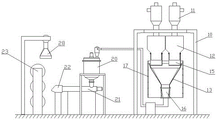
图1是本实用新型混合装置和成型装置的结构示意图。Fig. 1 is a structural schematic diagram of a mixing device and a molding device of the present invention.
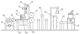
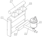
图2是本实用新型成型装置和收卷装置的结构示意图。Fig. 2 is a schematic structural view of the forming device and the winding device of the present invention.
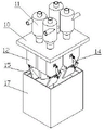
图3是本实用新型混合装置的结构示意图。Fig. 3 is a structural schematic diagram of the mixing device of the present invention.
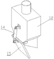
图4是本实用新型仓式计量称的结构示意图。Fig. 4 is a structural schematic diagram of the bin-type measuring scale of the present invention.
图5是本实用新型混合搅拌罐的剖视结构示意图。Fig. 5 is a schematic cross-sectional structure diagram of the mixing tank of the present invention.
图6是本实用新型成型装置的结构示意图。Fig. 6 is a schematic structural view of the molding device of the present invention.
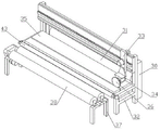
图7是本实用新型收卷装置的结构示意图。Fig. 7 is a schematic structural view of the winding device of the present invention.
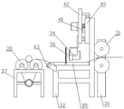
图8是本实用新型收卷装置的侧视结构示意图。Fig. 8 is a schematic side view of the winding device of the present invention.
具体实施方式Detailed ways
为使本发明实施例的目的、技术方案和优点更加清楚,下面将结合本发明实施例中的附图,对本发明实施例中的技术方案进行清楚、完整地描述,显然,所描述的实施例是本发明一部分实施例,而不是全部的实施例。通常在此处附图中描述和示出的本发明实施例的组件可以以各种不同的配置来布置和设计。因此,以下对在附图中提供的本发明的实施例的详细描述并非旨在限制要求保护的本发明的范围,而是仅仅表示本发明的选定实施例。基于本发明中的实施例,本领域普通技术人员在没有做出创造性劳动前提下所获得的所有其他实施例,都属于本发明保护的范围。应注意到:相似的标号和字母在下面的附图中表示类似项,因此,一旦某一项在一个附图中被定义,则在随后的附图中不需要对其进行进一步定义和解释。在本发明实施例的描述中,需要说明的是,若出现术语“上”、“下”、“内”、“外”等指示的方位或位置关系为基于附图所示的方位或位置关系,或者是该发明产品使用时惯常摆放的方位或位置关系,仅是为了便于描述本发明和简化描述,而不是指示或暗示所指的装置或元件必须具有特定的方位、以特定的方位构造和操作,因此不能理解为对本发明的限制。此外,本发明的描述中若出现术语“第一”、“第二”等仅用于区分描述,而不能理解为指示或暗示相对重要性。在本发明实施例的描述中,还需要说明的是,除非另有明确的规定和限定,若出现术语“设置”、“连接”应做广义理解,例如,可以是固定连接,也可以是可拆卸连接,或一体地连接;可以是机械连接,也可以是电连接;可以是直接相连,也可以通过中间媒介间接相连,可以是两个元件内部的连通。对于本领域的普通技术人员而言,可以具体情况理解上述术语在本发明中的具体含义。In order to make the purpose, technical solutions and advantages of the embodiments of the present invention clearer, the technical solutions in the embodiments of the present invention will be clearly and completely described below in conjunction with the drawings in the embodiments of the present invention. Obviously, the described embodiments It is a part of embodiments of the present invention, but not all embodiments. The components of the embodiments of the invention generally described and illustrated in the figures herein may be arranged and designed in a variety of different configurations. Accordingly, the following detailed description of the embodiments of the invention provided in the accompanying drawings is not intended to limit the scope of the claimed invention, but merely represents selected embodiments of the invention. Based on the embodiments of the present invention, all other embodiments obtained by persons of ordinary skill in the art without making creative efforts belong to the protection scope of the present invention. It should be noted that like numerals and letters denote similar items in the following figures, therefore, once an item is defined in one figure, it does not require further definition and explanation in subsequent figures. In the description of the embodiments of the present invention, it should be noted that if the orientation or positional relationship indicated by the terms "upper", "lower", "inner", "outer" etc. appear, it is based on the orientation or positional relationship shown in the drawings , or the orientation or positional relationship that the product of the invention is usually placed in use is only for the convenience of describing the present invention and simplifying the description, rather than indicating or implying that the device or element referred to must have a specific orientation or be constructed in a specific orientation and operation, and therefore should not be construed as limiting the invention. In addition, if the terms "first", "second" and the like appear in the description of the present invention, they are only used to distinguish the description, and should not be understood as indicating or implying relative importance. In the description of the embodiments of the present invention, it should also be noted that, unless otherwise specified and limited, the terms "setting" and "connection" should be interpreted in a broad sense, for example, it can be a fixed connection or an optional connection. Detachable connection, or integral connection; it can be mechanical connection or electrical connection; it can be direct connection or indirect connection through an intermediary, and it can be the internal communication of two components. Those of ordinary skill in the art can understand the specific meanings of the above terms in the present invention in specific situations.
如附图所示,本实用新型它包括混合装置、成型装置和收卷装置,As shown in the accompanying drawings, the utility model includes a mixing device, a forming device and a winding device,
混合装置包括上料支撑架10、一组真空上料机11、一组仓式计量称12和出料漏斗13,The mixing device includes a
一组真空上料机11的旋风分离器通过支架安装在上料支撑架10顶部,一组仓式计量称12安装在上料支撑架10上,真空上料机11的旋风分离器出料口与仓式计量称12的进料口相连通,仓式计量称12的底部设置有排料组件,The cyclone separator of one group of
排料组件包括排料气缸14和挡料盖体15,The discharge assembly includes a
仓式计量称12的出料口为斜口,仓式计量称12的出料口外壁上对称分布设置有一对挡板支架,挡料盖体15一端通过销轴活动安装在一对挡板支架上,挡料盖体15上设置有气缸连接座,排料气缸14的缸筒端部活动安装在仓式计量称12的外壁上,排料气缸14的活塞杆端部与气缸连接座活动连接,通过排料气缸14带动挡料盖体15绕销轴旋转,以开启或关闭仓式计量称12的出料口,The outlet of the warehouse-
出料漏斗13位于仓式计量称12出料口下方,出料漏斗13通过料斗支架安装在上料支撑架10底部;The
成型装置包括混合搅拌罐20、螺旋挤出机21、挤出机模头22、压延机23和抽气组件,The molding device comprises a
混合搅拌罐20包括罐体24、搅拌轴25和罐体真空上料机26,The mixing and stirring
罐体24底部设置有排料口,罐体24的排料口处设置有阀门,罐体24顶部设置有进料口,罐体真空上料机26的出料口与罐体24的进料口相连通,搅拌轴25上设置有螺旋叶片,搅拌轴25通过轴承活动安装在罐体24内,通过电动机驱动搅拌轴25旋转,The bottom of the
罐体24的排料口与螺旋挤出机21的进料口相连通,挤出机模头22安装在螺旋挤出机21的出料端,压延机23位于挤出机模头22出料口一侧,The discharge port of the
抽气组件包括抽气总管27和一组集尘罩28,The air extraction assembly includes an air extraction
抽气总管27上开有一组抽气口,一组集尘罩28的进气口分别与对应的抽气口相连通,集尘罩28位于压延机23上方;There is a group of air extraction ports on the air extraction
收卷装置包括进料机架30、一对进料辊筒31、切割组件和收卷组件,The winding device comprises a
一对进料辊筒31通过轴承活动安装在进料机架30上,A pair of feeding
切割组件包括切割机架32、电动滑台33和切割电机34,Cutting assembly comprises cutting
切割机架32上设置有一对切割支撑板35,一对切割支撑板35之间形成切割间隙,电动滑台33安装在切割机架32上,切割电机34安装在电动滑台33的滑块上,切割电机34的动力输出轴上设置有切割轮36,切割轮36底部位于切割间隙内,A pair of cutting
收卷组件包括收卷机架37和一对收卷辊筒38,The winding assembly includes a winding
一对收卷辊筒38通过轴承水平安装在收卷机架37上,并通过电动机驱动收卷辊筒38旋转,切割组件位于进料辊筒31和收卷组件之间;A pair of winding
罐体真空上料机26的进料口与出料漏斗13的出料口相连通,压延机23与一对进料辊筒31之间设置有一组中转输送辊筒100。The feed port of the
出料漏斗13出料口处设置有转接管道16,转接管道16的进料口为矩形,转接管道16的出料口为圆形;它还有遮挡屏17,遮挡屏17罩在出料漏斗13上。Discharging
仓式计量称12的外壁上设置有双耳座,排料气缸14的缸筒端部设置有单耳座,并通过单耳座和销轴活动安装在双耳座上;罐体24内设置有一对挡板。The outer wall of the bin-
挤出机模头22的出料口朝向压延机23的一对辊筒之间的辊压间隙;压延机23是三辊压延机。The discharge port of the extruder die
混合搅拌罐20、螺旋挤出机21、挤出机模头22和压延机23均通过机架安装在水平地面上。
一对进料辊筒31之间形成进料间隙,一对进料辊筒31的端部设置有相互啮合的传动齿轮,辊筒驱动电机安装在进料机架30上,辊筒驱动电机的动力输出轴与其中一个进料辊筒31端部转轴传动相连。A feed gap is formed between a pair of
电动滑台33包括滑座40、齿条41、滑动板42和驱动电机,Electric slide table 33 comprises
滑座40安装在切割机架32上,滑座40的侧壁和顶部分别设置有滑轨,齿条41安装在滑座40的侧壁上,滑动板42为倒置L形,滑动板42上设置有与滑轨相配的一对滑块,驱动电机安装在滑动板42上,驱动电机的动力输出轴上设置有齿轮,齿轮与齿条41啮合,滑动板42底部设置有电动机挂架,切割电机34安装在电动机挂架上。The
切割机架32的出料端设置有出料辊筒43。The discharge end of the cutting
收卷辊筒38的一端转轴上分别设置有链轮,辊筒驱动电机安装在收卷机架37上,辊筒驱动电机的动力输出轴上设置有链轮,辊筒驱动电机通过链轮和链条带动一对收卷辊筒38旋转。A sprocket wheel is respectively arranged on one end rotating shaft of the winding
工作方式及原理:通过一组真空上料机11将不同的防水板颗粒原料从存料箱底部的下料口处抽出至仓式计量称12内,称重后,排料气缸14的活塞杆收回,带动挡料盖体15绕销轴旋转,开启仓式计量称12的底部出料口,排出防水板颗粒原料至出料漏斗13内,多个仓式计量称12内的颗粒原料均落入出料漏斗13内,下料完毕后即可通过输送装置送至下一工位。出料漏斗13出料口处设置有转接管道16,转接管道16将出料漏斗13的矩形出料口转换成圆形出料口,方便连出料管道。出料漏斗13位于遮挡屏17内,防止原料飞溅,同时起到防止杂物进入出料漏斗13的作用。Working method and principle: Through a set of
通过罐体真空上料机26将防水板原料抽起至罐体24内,在电动机的带动下,搅拌轴25旋转,通过螺旋叶片将颗粒状的防水板原料混合搅拌均匀,然后开启阀门,防水板原料落入螺旋挤出机21内,防水板原料经过螺旋挤出机21加热融化后由挤出机模头22输出进入压延机23内,压制成型,压制成型后的防水板在输送辊的带动下进入下一工位。挤出机输出防水板时,产生的气体通过一组集尘罩28收集后由抽气总管27抽出。由于是颗粒原料采用螺旋叶片对其搅拌速度更快,搅拌均匀。The raw material of the waterproof board is pumped into the
经过一组一组中转输送辊筒100的输送,防水板在一对进料辊筒31的带动下进入到一对切割支撑板35上,然后通过出料辊筒43输出至一对收卷辊筒38上,工作人员手动将防水板卷成小卷,然后放置在一对收卷辊筒38之间,收卷辊筒38在电动机的带动下开始旋转,将防水板卷成大卷,卷到一定大小后,停止收卷,启动电动滑台33和切割电机34,通过切割轮36将防水板切断,工作人员取下防水板卷即可。驱动电机带动齿轮旋转,齿轮沿着齿条41运动,带动滑动板42在滑轨上左右移动。After being conveyed by a group of transfer conveying rollers 100, the waterproof board enters a pair of cutting
Claims (9)
Priority Applications (1)
| Application Number | Priority Date | Filing Date | Title |
|---|---|---|---|
| CN202221542996.5U CN217704795U (en) | 2022-06-20 | 2022-06-20 | Waterproof board production line for railway tunnel |
Applications Claiming Priority (1)
| Application Number | Priority Date | Filing Date | Title |
|---|---|---|---|
| CN202221542996.5U CN217704795U (en) | 2022-06-20 | 2022-06-20 | Waterproof board production line for railway tunnel |
Publications (1)
| Publication Number | Publication Date |
|---|---|
| CN217704795U true CN217704795U (en) | 2022-11-01 |
Family
ID=83801348
Family Applications (1)
| Application Number | Title | Priority Date | Filing Date |
|---|---|---|---|
| CN202221542996.5U Expired - Fee Related CN217704795U (en) | 2022-06-20 | 2022-06-20 | Waterproof board production line for railway tunnel |
Country Status (1)
| Country | Link |
|---|---|
| CN (1) | CN217704795U (en) |
-
2022
- 2022-06-20 CN CN202221542996.5U patent/CN217704795U/en not_active Expired - Fee Related
Similar Documents
| Publication | Publication Date | Title |
|---|---|---|
| CN217803455U (en) | Railway is waterproof board raw materials processing lines for tunnel | |
| CN211584313U (en) | A three-roller honey pill machine | |
| CN207252762U (en) | A kind of feed processing crushing extrusion all-in-one machine | |
| CN110640926A (en) | A kind of compounding silicone rubber production and preparation system and preparation process thereof | |
| CN117753536B (en) | Automatic feeder of broken recovery system of lithium cell | |
| CN114226048A (en) | Grinding mechanism for refractory material and grinding method thereof | |
| CN217704598U (en) | Forming and winding system for waterproof board for railway tunnel | |
| CN218854016U (en) | Fodder biax oar formula mixes machine | |
| CN217704794U (en) | Waterproof board raw material mixing and forming system for railway tunnel | |
| CN111070739A (en) | Production process and production device of environment-friendly rubber magnetic plate | |
| CN215783179U (en) | Blendor is used in preparation of aluminum alloy metal additive | |
| CN216578713U (en) | Grain device is cut to plastics pelleter | |
| CN215277552U (en) | Plastic particle crushing device | |
| CN213102510U (en) | Waste material breaker is used in processing of disposable cutlery box | |
| CN213762109U (en) | Raw material crushing device for plastic products | |
| CN212218940U (en) | A rubber production feeding room | |
| CN208392383U (en) | A kind of mixer | |
| CN217704599U (en) | Raw material extrusion molding device for waterproof board for railway tunnel | |
| CN219003274U (en) | Paper products leftover bits collection device | |
| CN111330479A (en) | High-speed mixing equipment for metallurgical powder of rotating part of engine | |
| CN221339718U (en) | Feeding device of flaker with mixing function | |
| CN217706635U (en) | Broken bag hybrid system of waterproof board raw materials for railway tunnel | |
| CN223657411U (en) | An automatic PVC pipe feeding machine | |
| CN222778138U (en) | Building construction waste crushing and recycling device | |
| CN221204060U (en) | Feed production processing device |
Legal Events
| Date | Code | Title | Description |
|---|---|---|---|
| GR01 | Patent grant | ||
| GR01 | Patent grant | ||
| CF01 | Termination of patent right due to non-payment of annual fee | ||
| CF01 | Termination of patent right due to non-payment of annual fee |
Granted publication date: 20221101 |