SUMMERY OF THE UTILITY MODEL
Not enough to prior art, the utility model provides a building is grinding device for aluminum alloy production possesses the advantages such as the regulation and positioning of being convenient for, has solved the problem of inconvenient regulation and positioning.
In order to achieve the above purpose, the utility model provides a following technical scheme: the utility model provides a grinding device is used in building aluminum alloy production, includes the workstation, the top fixedly connected with riser of workstation, the first motor of one side fixedly connected with of riser, the output shaft of first motor passes through shaft coupling fixedly connected with screw rod, the outer wall swing joint of screw rod has the screw thread slider, the back fixedly connected with movable plate of screw thread slider, the positive fixedly connected with second motor of movable plate, the output shaft of second motor passes through shaft coupling fixedly connected with head of polishing, one side fixedly connected with horizontal pole of riser.
The outer wall swing joint of horizontal pole has first spring, the outer wall swing joint of horizontal pole has first sliding sleeve, the top fixedly connected with second spring of first sliding sleeve, the inner wall swing joint of second spring has the bracing piece, the one end fixedly connected with locating rack of bracing piece, the inner wall swing joint of locating rack has the aluminum alloy, the outer wall swing joint of horizontal pole has the second sliding sleeve, the inner wall fixedly connected with gag lever post of second sliding sleeve, the mounting groove has been seted up at the top of workstation, the inner wall fixedly connected with dust absorption fan of mounting groove, the air intake fixedly connected with pipe of dust absorption fan, the air outlet fixedly connected with of dust absorption fan goes out the dirt pipe.
Furthermore, a bearing is arranged on one side of the vertical plate, an inner ring of the bearing is fixedly connected with one end of the screw rod, and the vertical plate is movably connected with the screw rod through the bearing.
Furthermore, the bottom of locating rack is respectively with the one end of second spring and the one end fixed connection of bracing piece, and the locating rack is the positioning rack of falling spill, and the inner wall of positioning rack is provided with the slipmat.
Furthermore, the outer wall of the cross rod is provided with a limiting groove, and the inner wall of the limiting groove is movably connected with the outer wall of the limiting rod.
Furthermore, one end of the conduit is fixedly connected with a dust absorption hopper, and the inner wall of the dust absorption hopper is fixedly connected with a protective net.
Furthermore, one end of the dust outlet pipe is fixedly connected with a dust collection box, the top of the dust collection box is fixedly connected with the bottom of the workbench, a water outlet is formed in one side of the dust outlet pipe, and a water drainage pipe is arranged at the bottom of the dust collection box.
Further, the top fixedly connected with buffer spring of second sliding sleeve, and buffer spring's inner wall is provided with the montant, and the second sliding sleeve passes through buffer spring and montant and locating rack swing joint.
Compared with the prior art, the technical scheme of the application has the following beneficial effects:
1. this building grinding device for aluminum alloy production, through first motor, the screw rod, the thread sliding block, the movable plate, the horizontal pole, first spring, first sliding sleeve, the second spring, the bracing piece, the locating rack, the aluminum alloy, the second sliding sleeve, gag lever post and spacing groove, the person of facilitating the use fixes a position the centre gripping to the aluminum alloy, and can be adapted to the aluminum alloy of different length, also can improve laminating and stability when fixing a position the centre gripping, also the person of facilitating the use adjusts the position of polishing of the head of polishing simultaneously when the cutting, not only the flexibility when having improved the use greatly, also bring convenience for user's polishing work simultaneously, the demand of using has been satisfied, grinding device's result of use has been improved.
2. This building is grinding device for aluminum alloy production, through dust absorption fan, pipe, dust absorption fill, protection network, play dirt pipe and dust collection box, not only can collect unified the processing to the sweeps that produces when the work of polishing to the protection network that sets up in the dust absorption fill can reduce debris and drop into the circumstances that causes the trouble in the dust absorption fill, and it is troublesome to reduce unnecessary use, improves the practicality simultaneously, and further person of facilitating the use's the work of polishing reduces the sweeps that flies upward in the air and influences workman's health.
Detailed Description
The technical solutions in the embodiments of the present invention will be described clearly and completely with reference to the accompanying drawings in the embodiments of the present invention, and it is obvious that the described embodiments are only some embodiments of the present invention, not all embodiments. Based on the embodiments in the present invention, all other embodiments obtained by a person skilled in the art without creative efforts all belong to the protection scope of the present invention.
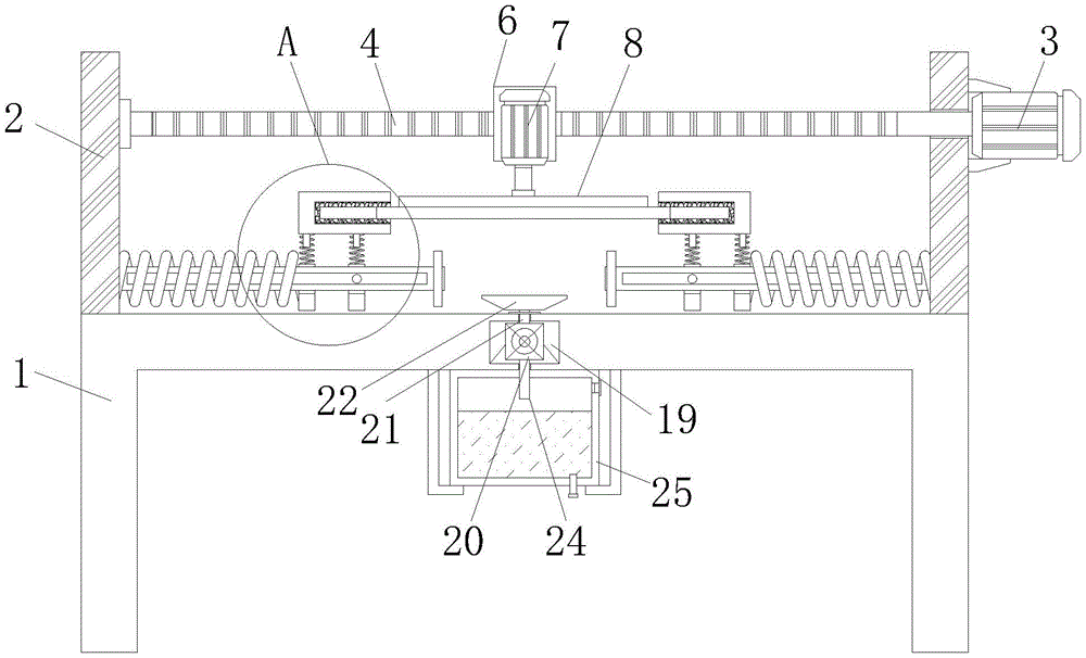
Please refer to fig. 1-5, the polishing device for the production of building aluminum alloy in this embodiment includes a workbench 1, a vertical plate 2 is fixedly connected to the top of the workbench 1, a first motor 3 is fixedly connected to one side of the vertical plate 2, an output shaft of the first motor 3 is fixedly connected to a screw rod 4 through a coupler, an outer wall of the screw rod 4 is movably connected to a thread slider 5, a movable plate 6 is fixedly connected to the back of the thread slider 5, a second motor 7 is fixedly connected to the front of the movable plate 6, an output shaft of the second motor 7 is fixedly connected to a polishing head 8 through a coupler, and a cross rod 9 is fixedly connected to one side of the vertical plate 2.
The outer wall of the cross rod 9 is movably connected with a first spring 10, the outer wall of the cross rod 9 is movably connected with a first sliding sleeve 11, the top of the first sliding sleeve 11 is fixedly connected with a second spring 12, the inner wall of the second spring 12 is movably connected with a supporting rod 13, one end of the supporting rod 13 is fixedly connected with a positioning frame 14, the inner wall of the positioning frame 14 is movably connected with an aluminum alloy 15, the outer wall of the cross rod 9 is movably connected with a second sliding sleeve 16, and the inner wall of the second sliding sleeve 16 is fixedly connected with a limiting rod 17, a user can conveniently position and clamp the aluminum alloy 15 through the first motor 3, the screw rod 4, the threaded sliding block 5, the moving plate 6, the cross rod 9, the first spring 10, the first sliding sleeve 11, the second spring 12, the supporting rod 13, the positioning frame 14, the aluminum alloy 15, the second sliding sleeve 16, the limiting rod 17 and the limiting groove 18, and can adapt to aluminum alloys 15 with different lengths, and the joint and stability can be improved during positioning and clamping, meanwhile, the polishing position of the polishing head 8 can be conveniently adjusted by a user during cutting, the flexibility during use is greatly improved, the polishing work of the user is facilitated, the use requirement is met, the use effect of the polishing device is improved, the top of the workbench 1 is provided with the mounting groove 19, the inner wall of the mounting groove 19 is fixedly connected with the dust suction fan 20, the air inlet of the dust suction fan 20 is fixedly connected with the guide pipe 21, the air outlet of the dust suction fan 20 is fixedly connected with the dust outlet pipe 24, the dust generated during polishing work can be collected and uniformly processed through the dust suction fan 20, the guide pipe 21, the dust suction hopper 22, the protective net 23, the dust outlet pipe 24 and the dust collection box 25, the situation that sundries fall into the dust suction hopper 22 to cause faults can be reduced through the protective net 23 arranged in the dust suction hopper 22, and unnecessary use troubles are reduced, improve the practicality simultaneously, further person's of facilitating the use's work of polishing reduces the sweeps that flies upward in the air and influences workman's health.
Referring to fig. 1, in the present embodiment, a bearing is disposed on one side of the vertical plate 2, an inner ring of the bearing is fixedly connected to one end of the screw rod 4, and the vertical plate 2 is movably connected to the screw rod 4 through the bearing.
The screw 4 can be supported.
Referring to fig. 3, in the present embodiment, the bottom of the positioning frame 14 is fixedly connected to one end of the second spring 12 and one end of the supporting rod 13, the positioning frame 14 is an inverted concave positioning frame, and the inner wall of the positioning frame 14 is provided with a non-slip mat.
It should be noted that a good buffering effect can be achieved during polishing, and the adhesion degree between the aluminum alloy 15 and the polishing head 8 is improved during polishing.
Referring to fig. 3, in the present embodiment, the outer wall of the cross bar 9 is provided with a limiting groove 18, and the inner wall of the limiting groove 18 is movably connected with the outer wall of the limiting rod 17.
It is noted that stability can be improved when the first and second sliding sleeves 11, 16 are moved.
Referring to fig. 5, in the present embodiment, one end of the duct 21 is fixedly connected to a dust collecting bucket 22, and the inner wall of the dust collecting bucket 22 is fixedly connected to a protective net 23.
It should be noted that, the falling of the impurities into the dust suction hopper 22 can be reduced, and the occurrence of faults is avoided.
Referring to fig. 1, in the present embodiment, one end of the dust outlet pipe 24 is fixedly connected to a dust box 25, the top of the dust box 25 is fixedly connected to the bottom of the worktable 1, a water outlet is formed at one side of the dust outlet pipe 24, and a drain pipe is arranged at the bottom of the dust box 25.
It should be noted that collected scraps can be cleaned to avoid the situation that the scraps are raised secondarily.
Referring to fig. 3, in the embodiment, a buffer spring is fixedly connected to the top of the second sliding sleeve 16, a vertical rod is disposed on an inner wall of the buffer spring, and the second sliding sleeve 16 is movably connected to the positioning frame 14 through the buffer spring and the vertical rod.
It should be noted that the buffer effect is good when polishing, and the fitting degree between the aluminum alloy 15 and the polishing head 8 is improved when polishing.
It can be understood that, this building grinding device for aluminum alloy production, the person of facilitating the use fixes a position the centre gripping to aluminum alloy 15, and can be adapted to the aluminum alloy 15 of different length, also can improve laminating and stability when fixing a position the centre gripping, also the person of facilitating the use adjusts the position of polishing of head 8 when the cutting simultaneously, not only improve the flexibility when using greatly, also bring the facility for user's the work of polishing simultaneously, the demand of using has been satisfied, grinding device's result of use has been improved.
The working principle of the embodiment is as follows:
during operation, an aluminum alloy 15 to be polished is placed in the positioning frame 14, the positioning frame 14 is pulled to one side, the first sliding sleeve 11 and the second sliding sleeve 16 at the bottom of the positioning frame 14 slide on the cross rod 9, and the first spring 10 on the outer wall of the cross rod 9 is extruded to deform, so that the inner walls of the two positioning frames 14 and the two ends of the aluminum alloy 15 are clamped and positioned, then the first motor 3 is started, the first motor 3 operates to drive the screw rod 4 to rotate, the screw slider 5 is driven to move while the screw rod 4 rotates to drive the movable plate 6 and the second motor 7 to move, so that the polishing position of the polishing head 8 can be adjusted, after the first motor 3 is adjusted to a proper position, the second motor 7 operates to drive the polishing head 8 to rotate and polish the surface of the aluminum alloy 15, the second spring 12 at the bottom of the positioning frame 14 can start an effect of reducing pressure during polishing, and the polishing effect is improved, and the practicability of the polishing device is improved.
It is noted that, herein, relational terms such as first and second, and the like may be used solely to distinguish one entity or action from another entity or action without necessarily requiring or implying any actual such relationship or order between such entities or actions. Also, the terms "comprises," "comprising," or any other variation thereof, are intended to cover a non-exclusive inclusion, such that a process, method, article, or apparatus that comprises a list of elements does not include only those elements but may include other elements not expressly listed or inherent to such process, method, article, or apparatus. Without further limitation, an element defined by the phrases "comprising a," "8230," "8230," or "comprising" does not exclude the presence of additional like elements in a process, method, article, or apparatus that comprises the element.
Although embodiments of the present invention have been shown and described, it will be appreciated by those skilled in the art that various changes, modifications, substitutions and alterations can be made in these embodiments without departing from the principles and spirit of the invention, the scope of which is defined in the appended claims and their equivalents.