CN217662332U - Novel wet purifier - Google Patents
Novel wet purifier Download PDFInfo
- Publication number
- CN217662332U CN217662332U CN202220729865.1U CN202220729865U CN217662332U CN 217662332 U CN217662332 U CN 217662332U CN 202220729865 U CN202220729865 U CN 202220729865U CN 217662332 U CN217662332 U CN 217662332U
- Authority
- CN
- China
- Prior art keywords
- plate
- cyclone
- rotational flow
- spray
- ring
- Prior art date
- Legal status (The legal status is an assumption and is not a legal conclusion. Google has not performed a legal analysis and makes no representation as to the accuracy of the status listed.)
- Active
Links
Images


Classifications
-
- Y—GENERAL TAGGING OF NEW TECHNOLOGICAL DEVELOPMENTS; GENERAL TAGGING OF CROSS-SECTIONAL TECHNOLOGIES SPANNING OVER SEVERAL SECTIONS OF THE IPC; TECHNICAL SUBJECTS COVERED BY FORMER USPC CROSS-REFERENCE ART COLLECTIONS [XRACs] AND DIGESTS
- Y02—TECHNOLOGIES OR APPLICATIONS FOR MITIGATION OR ADAPTATION AGAINST CLIMATE CHANGE
- Y02A—TECHNOLOGIES FOR ADAPTATION TO CLIMATE CHANGE
- Y02A50/00—TECHNOLOGIES FOR ADAPTATION TO CLIMATE CHANGE in human health protection, e.g. against extreme weather
- Y02A50/20—Air quality improvement or preservation, e.g. vehicle emission control or emission reduction by using catalytic converters
- Y02A50/2351—Atmospheric particulate matter [PM], e.g. carbon smoke microparticles, smog, aerosol particles, dust
Abstract
The utility model provides a novel wet purifier, which comprises a shell, wherein the shell is provided with an air inlet and an air outlet, a sewer pipe, a rotational flow component, a sprayer component, a spray header and a spray water pump, and the outlet of the spray water pump is connected with the water inlet of the spray header; the downcomer sets up the casing bottom, the air outlet sets up the casing top, the air intake sets up in the casing lower part, whirl subassembly with the spray thrower subassembly sets up in the casing between air intake and air outlet, the delivery port of shower pipe sets up in the casing, the baffle support bar with the shower pipe is connected, the delivery port of shower pipe with it is relative to spray the baffle. The utility model discloses can effectively carry out wet dedusting, dust removal effect good, compact structure, take up an area of for a short time to dirty gas, and spray that the flow is low, the pressure loss is little, non-clogging, highly little to the energy consumption is low, and the range of application is extensive, has higher commercialization and spreading value.
Description
Technical Field
The utility model relates to an industrial dust removal and waste gas treatment field, more specifically say, relate to a novel wet purifier.
Background
The wet dust collector is commonly called as a demister, and is a device which makes dust-containing gas and liquid (generally water) closely contact, utilizes the inertia collision of water drops and particles or utilizes the full mixing action and other actions of water and dust to capture the particles or enlarge or retain the particles in a fixed container to achieve the effect of separating the water from the dust. The wet dust collector is produced by combining two forms of water bath and spraying, the dust-containing gas is pressed into a water tank filled with water with a certain height by utilizing the suction force of a high-pressure centrifugal fan, part of dust is adsorbed in the water by the water bath, the gas flows from bottom to top after being uniformly distributed and shunted, a high-pressure spray head in the wet dust collector sprays water mist from top to bottom to collect the rest dust particles, and the filtering efficiency of the wet dust collector can reach more than 85 percent. In industrial dust removal, wet dust collectors are widely used because of their advantages of low investment, no secondary dust emission, being resistant to adhesion, fire and explosion, and can effectively remove liquid or solid particles with a diameter of 0.1-20 μm from an air stream, and also remove a part of gaseous pollutants. The wet dust collector has the advantages of simple structure, convenient operation, convenient maintenance and high purification efficiency, can treat high-temperature and high-humidity airflow, and minimizes the possibility of ignition and explosion.
However, when a wet dust collector is adopted, special attention needs to be paid to the problems of equipment and pipeline corrosion, sewage and sludge treatment and the like, and the wet dust collection process is not beneficial to the recovery of byproducts. If the equipment is installed indoors, the problem that the equipment may freeze in winter must also be considered. Further, if the efficiency of removing fine particles is high, the liquid phase needs to be dispersed more favorably, but the energy consumption increases. In addition, in various wet dust removal purifiers, the cyclone mixed-motion spray tower has the defects of easy blockage and large occupied area, the filler spray tower has the defects of easy blockage and high height, the cyclone plate spray tower is also easy to bring water to the outside due to high height, and the venturi wet dust remover has high pressure loss, so that the more extensive application of the venturi wet dust remover is limited to a certain extent due to the defects of the wet dust remover.
SUMMERY OF THE UTILITY MODEL
The to-be-solved technical problem of the utility model is to provide a novel wet purifier to solve the problem that conventional wet dust collector occupies an area of big, easy jam, loss are big on the market at present.
In order to solve the problems, the utility model comprises a shell, wherein the shell is provided with an air inlet, an air outlet, a sewer pipe, a rotational flow component, a sprayer component, a spray header and a spray water pump, and the outlet of the spray water pump is connected with the water inlet of the spray header;
the lower water pipe is arranged at the bottom of the shell, the air outlet is arranged at the top of the shell, the air inlet is arranged at the lower part of the shell, the rotational flow component and the sprayer component are arranged on the shell between the air inlet and the air outlet, the sprayer component comprises a dust accumulation prevention block, a spraying baffle plate and a baffle plate supporting strip which are sequentially connected from top to bottom, and the upper part of the dust accumulation prevention block is an inclined plane;
the delivery port setting of spray header is in the casing, the baffle support bar with spray header connects, just spray header's delivery port with it is relative to spray the baffle for can spout extremely through spray header spun water on the baffle.
The utility model discloses an above design, the design of supreme admitting air has been solved to the dust remover from following to the adoption, through with whirl subassembly and sprayer subassembly setting in the casing and between air intake, the air outlet, can carry out wet-type dust removal to the gas that gets into in the casing effectively and filter, just the utility model discloses the spray header that sets up is relative with the spray baffle two, can erupt the water curtain to enlarge the area that removes dust, through the design of preventing the laying dust piece, can avoid the problem of laying dust of sprayer subassembly itself, solved the problem of easy jam, and the utility model discloses after gas gets into to casing inside, only need open spray header can begin to remove dust to gaseous wet-type, solved the big problem of loss.
According to the preferable scheme, the spray water pipe comprises a water pipe body and a water pipe elbow, one end of the water pipe body is connected with the spray water pump, the other end of the water pipe body is connected with the water pipe elbow, and an outlet of the water pipe elbow is upwards arranged and is right opposite to the lower bottom surface of the spray baffle.
Through the design of the water pipe elbow, the water outlet of the spray water pipe can be just opposite to the spray baffle, so that the dust removal effect of the spray water curtain is improved.
Preferably, the water spraying pipe is provided with a water quantity regulating valve.
The size of the water sprayed by the spray water pipe can be controlled through the water quantity regulating valve, so that the size of the spray water curtain is regulated, the regulation is convenient when different gases enter, and the loss of the equipment is reduced.
Preferably, the cyclone assembly comprises a cyclone air inlet pipe, a first cyclone plate group, a second cyclone plate group and a third cyclone plate group, and the cyclone air inlet pipe is arranged on the air inlet.
Through the arrangement of the cyclone air inlet pipe, gas to be treated enters from the cyclone air inlet pipe in a tangential direction, small cyclones are formed along the wall, dust particles or waste gas contained in the gas are mixed with the water film and the vortex of the air inlet cavity in a flushing mode to form a first stage of spraying purification, and then the gas enters the first cyclone plate group, the second cyclone plate group and the third cyclone plate group to be treated continuously.
Preferably, the housing comprises a first cylinder, a variable diameter body connecting pipe and a second cylinder which are sequentially connected from top to bottom, and the diameter of the first cylinder is larger than that of the second cylinder.
As a preferable scheme, the first cyclone plate group is arranged in the second cylinder, the second cyclone plate group and the third cyclone plate group are arranged in the first cylinder, the bottom of the second cyclone plate group is connected with the variable diameter body connecting pipe, and the top of the third cyclone plate group is communicated with the air outlet; the spray water pipe extends into the reducing body connecting pipe.
The shell is divided into three parts by the first cylinder, the second cylinder and the variable diameter body connecting pipe between the first cylinder and the second cylinder, the first rotational flow plate group is arranged in the second cylinder, namely, the gas treated by the rotational flow air inlet pipe is combined with a spraying water film flowing from the upper part in the process of further ascending along with the second cylinder to form secondary spraying purification; then the gas is introduced into the first cyclone plate group, the rotation motion is further enhanced, and the gas is directly contacted with a water curtain sprayed by the sprayer assembly after leaving the first cyclone plate group to form third-stage spraying purification; then the gas enters a second rotational flow plate group and a third rotational flow plate group in the first cylinder in sequence, and due to the action of the rotational force, dust and water mist are thrown to the side wall of the shell and flow out from a lower sewer pipe.
Preferably, the dust-accumulation-preventing block is a cone, and the bottom surface of the cone is connected with the spraying baffle.
The dust accumulation prevention block is in a cone shape, so that dust and water mist falling from the upper part can be effectively prevented from accumulating on the sprayer assembly, and frequent cleaning and maintenance are not needed.
As a preferable scheme, the first rotational flow plate group comprises a first rotational flow plate outer ring, a plurality of first rotational flow plate blades, a first rotational flow plate inner ring and a first rotational flow plate central disc which are sequentially connected from outside to inside, and the plurality of first rotational flow plates are uniformly distributed between the first rotational flow plate outer ring and the first rotational flow plate inner ring in a surrounding manner and are fixedly connected with the first rotational flow plate outer ring and the first rotational flow plate inner ring; the size and the shape of the first rotational flow plate center plate are the same as those of the inner side wall of the first rotational flow plate inner ring, and the outer wall of the first rotational flow plate center plate is connected with the inner side wall of the first rotational flow plate inner ring
As a preferred scheme, the second rotational flow plate group comprises a second rotational flow plate outer ring, a plurality of second rotational flow plate blades, a second rotational flow plate inner ring and a second rotational flow plate center plate, the second rotational flow plates are uniformly distributed around the second rotational flow plate outer ring and the second rotational flow plate inner ring and are fixedly connected with the second rotational flow plate outer ring and the second rotational flow plate inner ring, the size and the shape of the second rotational flow plate center plate are the same as those of the inner side wall of the second rotational flow plate inner ring, and the outer wall of the first rotational flow plate center plate is connected with the inner side wall of the first rotational flow plate inner ring.
As a preferred scheme, the third cyclone plate set includes a cyclone bottom plate, a bottom plate ring and cyclone rotor plates, the cyclone bottom plate is provided with a hole having the same size and shape as the bottom plate ring, the bottom plate ring is disposed on the upper portion of the hole and the bottom of the bottom plate ring is connected to the cyclone bottom plate, the plurality of cyclone rotor plates are disposed in the bottom plate ring and fixedly connected to the inner wall of the bottom plate ring, and the outer side wall of the bottom plate ring is connected to the housing on one side of the air inlet.
Through the setting of whirl board leaf and swirler pterygoid lamina, can be rotatory with gas to play the effect of beating the casing lateral wall with large granule material, improve the holistic dust removal performance of equipment.
The utility model provides a novel wet purifier can carry out wet-type dust removal to dirty gas effectively, and dust removal effect is good, and compact structure, area are little and spray that the flow is low, the pressure loss is little, there is not jam, advantage highly little, and the utility model relates to a novel wet purifier's energy consumption is low, and the range of application is extensive, has higher commercialization and spreading value.
Drawings
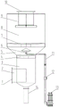
Fig. 1 is a schematic front structural view of a novel wet-type purifier of the present invention;
fig. 2 is a schematic top view of the novel wet-type purifier of the present invention;
fig. 3 is a schematic front structural view of a first cyclone plate group of the novel wet-type purifier of the present invention;
fig. 4 is a schematic top view of the first cyclone plate set of the novel wet purifier of the present invention;
fig. 5 is a schematic side view of a second cyclone plate group of the novel wet-type purifier according to the present invention;
fig. 6 is a schematic top view of a second cyclone plate set of the novel wet purifier of the present invention;
fig. 7 is a schematic side view of a third group of cyclone plates of a novel wet-type purifier according to the present invention;
fig. 8 is a schematic top view of a third group of cyclone plates of a novel wet-type purifier according to the present invention;
fig. 9 is a schematic structural view of a novel wet purifier sprayer assembly of the present invention (excluding spray and water pump water regulation valves);
description of reference numerals:
1. an air inlet; 2. a cyclone air inlet pipe; 3. a second cylinder; 4. a first set of swirl plates; 41. a first swirl plate outer ring; 42. a first swirl plate vane; 43. a first swirl plate inner ring; 44. a first swirl plate central disk; 5. the reducing body connecting pipe; 6. a sprayer assembly; 61. dust accumulation prevention blocks; 62. a spray baffle; 63. the baffle plate support bars; 64. a water pipe elbow; 7. a second set of swirl plates; 71. a second swirl plate outer ring; 72. a second swirl plate vane; 73. a second swirl plate inner ring; 74. a second whirl plate center plate; 8. a first cylinder; 9. a third cyclone plate group; 91. a swirler floor; 92. a floor ring; 93. A swirler rotor plate; 10. an air outlet; 11. a spray header; 12. a water quantity regulating valve; 13. a spray water pump; 14. a sewer pipe.
Detailed Description
The technical solution of the present invention will be described clearly and completely below, and it should be understood that the described embodiments are some, but not all embodiments of the present invention. Based on the embodiments in the present invention, all other embodiments obtained by a person skilled in the art without creative work belong to the protection scope of the present invention.
As shown in fig. 1-9, fig. 1 is a schematic view of the overall structure of a novel wet-type purifier of the present invention, fig. 2 is a schematic view of the top view structure of a novel wet-type purifier of the present invention, the present invention includes a housing, and a vortex assembly and a shower assembly 6 are arranged inside the housing; the shell consists of a first barrel 8 and a second barrel 3 which are sequentially arranged from top to bottom, the inner diameter of the first barrel 8 is larger than that of the second barrel 3, the first barrel 8 is connected with the second barrel 3 through a reducing body connecting pipe 5, a sewer pipe 14 is arranged at the bottom of the second barrel 3, and the sewer pipe 14 can also be connected with the second barrel 3 and the sewer pipe 14 through reducing bodies with the matched calibers; the lower opening of the first cylinder 8 is reduced and then connected to the downcomer 14, and the lower opening of the downcomer 14 is inserted into a circulating water body. As different embodiments, the lower opening of the first cylinder 8 can be directly inserted into the circulating water body without reducing;
the length of the first cylinder 8 can be increased as appropriate, so that the time of water film spraying (secondary spraying) on the inner wall of the first cylinder 8 is prolonged, and the effect of secondary spraying is further enhanced; an air outlet 10 is formed in the top of the first cylinder 8, an air inlet 1 is formed in the side wall of the second cylinder 3, and generally, the air inlet 1 is formed in the side wall of the second cylinder 3, which is close to the lower part;
as shown in fig. 3 to 8, the swirl assembly includes a swirl air inlet pipe 2, a first swirl plate group 4, a second swirl plate group 7 and a third swirl plate group 9, and includes that the first swirl plate group 4 includes a first swirl plate outer ring 41, first swirl plate blades 42, a first swirl plate inner ring 43 and a first swirl plate central disk 44, which are sequentially connected from outside to inside, and a plurality of first swirl plate blades 42 are uniformly distributed around between the first swirl plate outer ring 41 and the first swirl plate inner ring 43 and are fixedly connected to the first swirl plate outer ring 41 and the first swirl plate inner ring 43; the second cyclone plate group 7 and the first cyclone plate group 4 have the same shape, the second cyclone plate group 7 includes a second cyclone plate outer ring 71, second cyclone plate blades 72, a second cyclone plate inner ring 73 and a second cyclone plate central disk 74, and the second cyclone plate blades 72 are uniformly distributed around the second cyclone plate outer ring 71 and the second cyclone plate inner ring 73 and are fixedly connected with the second cyclone plate outer ring 71 and the second cyclone plate inner ring 73; the third cyclone plate group 9 includes a cyclone bottom plate 91, a bottom plate ring 92 and cyclone plates 93, the cyclone plates 93 are fixedly connected to the inner ring of the bottom plate ring 92, and the bottom of the bottom plate ring 92 is connected to the cyclone bottom plate 91, specifically, a hole having the same size and shape as the bottom plate ring 92 is formed in the cyclone bottom plate 91, the bottom plate ring 92 is disposed on the upper portion of the hole, the bottom of the bottom plate ring 92 is connected to the cyclone bottom plate 91, the cyclone plates 93 are disposed in the bottom plate ring 92 and are fixedly connected to the inner wall of the bottom plate ring 92, and the outer side wall of the bottom plate ring 92 is connected to the casing on the side of the air inlet 1;
first whirl board leaf 42 is the rotatory water conservancy diversion flat plate blade of air current, and quantity is a plurality of, is the narrow trapezoidal of slant length according to required whirl direction, just first whirl board leaf 42 one end weld in on the first whirl board outer loop 41, the other end weld in on the first whirl board inner loop 43. The first rotational flow plate central disk 44 is a small circular flat plate, is small in size, is welded with the first rotational flow plate inner ring 43, and is used for connecting and fixing a plurality of first rotational flow plate blades 42 on the periphery of the first rotational flow plate central disk. The first cyclone plate group 4 is fixed on the inner wall of the first cylinder 8 by peripheral welding (generally intermittent welding).
The second cyclone plate blades 72 are flat plate blades with rotary airflow guide, the number of the second cyclone plate blades is multiple, the second cyclone plate blades are obliquely long and narrow trapezoids according to the required cyclone direction, one end of each second cyclone plate blade 72 is welded on the second cyclone plate outer ring 71, and the other end of each second cyclone plate blade is welded on the second cyclone plate inner ring 73. The second rotational flow plate central disk 74 is a small circular flat plate, is small in size, is welded with the second large rotational flow plate inner ring, and is used for connecting and fixing a plurality of second rotational flow plate blades 72 on the periphery of the second rotational flow plate central disk. The periphery of the second cyclone plate group 7 is welded (generally, intermittently welded) and fixed on the inner wall of the second cylinder 3.
The cyclone air inlet pipe 2 is arranged on one side of the air inlet 1, the first cyclone plate group 4 is arranged on the upper portion of the second cylinder 3, the second cyclone plate group 7 is arranged on the lower portion, generally the bottom, of the first cylinder 8, the third cyclone plate group 9 is arranged on the upper portion, generally the top, of the first cylinder 8, and the upper portion of the third cyclone plate group 9 is communicated with the top of the first cylinder 8, generally, an opening on the upper portion of the third cyclone plate group 9 is equivalent to an aperture of an air outlet 10 on the upper portion of the first cylinder 8, that is, gas treated by the third cyclone plate group 9 directly can leave the equipment through the air outlet 10;
the third swirl plate group 9 includes a swirler bottom plate 91, a bottom plate ring 92 and swirler swirling plates 93, the swirler swirling plates 93 are fixedly connected with an inner ring of the bottom plate ring 92, and the bottom of the bottom plate ring 92 is connected with the swirler bottom plate 91; the bottom plate ring 92 is formed by rolling a narrow plate strip, and the upper opening of the bottom plate ring is welded to the periphery of the bottom plate 91 (a large disc flat plate) of the cyclone, and the bottom plate ring is combined in the purifier to play a role in blocking flow by a baffle plate. The cyclone rotor plate 93 is generally more than 3 and is in the shape of a rotor, the direction of the cyclone rotor plate is consistent with the rotation direction of the air flow of the purifier, and the cyclone rotor plate plays a role in receiving the tail part of the air flow rotation. The central cyclone is welded and fixed on the central air outlet opening of the top plate of the first barrel 8;
a sprayer assembly 6 is arranged in the reducing body connecting pipe 5, as shown in fig. 9, the sprayer assembly 6 comprises a dust accumulation prevention block 61, a spraying baffle 62 and a baffle support bar 63 which are sequentially connected from top to bottom, the baffle support bar 63 fixes a water outlet of a spraying water pipe 11, the water outlet of the spraying water pipe 11 is opposite to the spraying baffle 62, under general conditions, the spraying water pump 13 is arranged outside the shell, one end of the spraying water pipe 11 is connected with the spraying water pump 13, the other end of the spraying water pipe is arranged inside the reducing body connecting pipe 5 and is connected with a water pipe elbow 64, the water outlet of the water pipe elbow 64 is just opposite to the spraying baffle 62, so that water sprayed out of the spraying water pipe 11 can vertically hit the spraying baffle 62 to generate a spraying water curtain along the circumferential direction, the dust accumulation prevention block 61 is generally a cone, and the plane is connected with the upper part of the spraying baffle 62; the spray water pipe 11 is provided with a water quantity regulating valve 12, the air inlet 1 and the air outlet 10 are both provided with flanges, the size of the flanges can be regulated according to the equipment accessed by the air inlet 1 and the air outlet 10, the flanges are arranged on the air inlet and the air outlet, the flanges can be directly connected with the equipment for discharging gas to be treated and can be used for introducing the filtered gas into other equipment for treatment in the next step, and the arrangement of the flanges improves the compatibility of the utility model and can be directly communicated with other equipment;
the utility model discloses a theory of operation: the utility model relates to a novel wet purifier adopts upper and lower level whirl device, from up being equipped with whirl air-supply line 2, first whirl board group 4, second whirl board group 7 and third whirl board group 9 respectively down. The dust-containing gas tangentially enters the shell from the air inlet 1, small cyclones are formed along the wall, and dust particles or waste gas contained in the gas are mixed with the water film vortex of the air inlet cavity in a flushing manner to form first-stage spraying purification; then, the airflow continuously rotates and rises along the first cyclone plate group 4, and the spraying water films flowing downwards are mixed (the longer the first cyclone plate group 4 is, the longer the spraying mixing time is), so that the second stage of spraying purification is formed. Then the air current is rotatory through first whirl board group 4, and rotary motion is further strengthened to spray the water curtain through the spray that spray ware subassembly 6 arranged above first whirl board group 4 sprays, spray the water curtain and rise air current whirl and strongly and evenly mutually arouse, and dust particulate matter or waste gas that contain in the gas are adsorbed by the shower water once more and are absorbed, form the third level and spray the purification (mainly spray), and most moist dust and water smoke are separated by direct and are down backward flow along first whirl board leaf 42 and reducing body connecting pipe 5 inner wall. The airflow carrying the residual wet dust and water mist subsequently bypasses the spraying baffle plate 62 to rotate and enter the second cyclone plate group 7, then rotates and goes up to the third cyclone plate group 9 arranged at the top, the airflow rotation is reinforced twice, the centrifugal action is increased, the residual wet dust and water mist in the airflow are thrown to the inner wall of the first cylinder 8 under the strong centrifugal action and flow back downwards along the inner wall, the airflow after separation and purification is discharged from the central air outlet 10 at the top, and the water with dust after treatment is discharged from the sewer pipe 14 at the bottom, so that the treatment is completed; the size of the spray water curtain can also be adjusted by adjusting the water quantity adjusting valve 12.
Although the present disclosure has been described above, the scope of the present disclosure is not limited thereto. Those skilled in the art can make various changes and modifications without departing from the spirit and scope of the present disclosure, and such changes and modifications will fall within the scope of the present disclosure.
Claims (10)
1. A novel wet purifier is characterized in that: the device comprises a shell, wherein an air inlet (1), an air outlet (10), a sewer pipe (14), a rotational flow component, a sprayer component (6), a spray header (11) and a spray water pump (13) are arranged on the shell, and an outlet of the spray water pump (13) is connected with a water inlet of the spray header (11);
the sewer pipe (14) is arranged at the bottom of the shell, the air outlet (10) is arranged at the top of the shell, the air inlet (1) is arranged at the lower part of the shell, the rotational flow component and the sprayer component (6) are arranged in the shell between the air inlet (1) and the air outlet (10), and the sprayer component (6) comprises a dust accumulation prevention block (61), a spraying baffle plate (62) and a baffle plate support bar (63) which are sequentially connected from top to bottom;
the delivery port setting of shower pipe (11) is in the casing, baffle support bar (63) with shower pipe (11) are connected, just the delivery port of shower pipe (11) with it is relative to spray baffle (62), make through shower pipe (11) spun hydroenergy can spout extremely on spraying baffle (62).
2. A new wet scrubber according to claim 1, characterized in that; spray header (11) include water pipe body and water pipe elbow (64), the one end of water pipe body with spray pump (13) are connected, the other end of water pipe body with water pipe elbow (64) link to each other, the export of water pipe elbow (64) sets up and just right the lower bottom surface of baffle (62) sprays.
3. A new wet scrubber according to claim 1, characterized in that: and a water quantity regulating valve (12) is arranged on the spray water pipe (11).
4. A new wet scrubber according to claim 1, characterized in that: the dust accumulation prevention block (61) is a cone, and the bottom surface of the cone is connected with the spraying baffle (62).
5. A new wet scrubber according to claim 1, characterized in that: the cyclone assembly comprises a cyclone air inlet pipe (2), a first cyclone plate group (4), a second cyclone plate group (7) and a third cyclone plate group (9), the cyclone air inlet pipe (2) is communicated with the air inlet (1), and the first cyclone plate group (4), the second cyclone plate group (7) and the third cyclone plate group (9) are sequentially arranged in the shell from bottom to top and are connected with the inner wall of the shell.
6. The new wet scrubber according to claim 5, wherein: the shell comprises a first cylinder body (8), a variable diameter body connecting pipe (5) and a second cylinder body (3), wherein the first cylinder body (8), the variable diameter body connecting pipe (5) and the second cylinder body (3) are sequentially connected from top to bottom, and the diameter of the first cylinder body (8) is larger than that of the second cylinder body (3).
7. The new wet scrubber according to claim 6, wherein: the first cyclone plate group (4) is arranged in the second cylinder (3), the top of the first cyclone plate group (4) is connected with the bottom of the variable diameter body connecting pipe (5), the second cyclone plate group (7) and the third cyclone plate group (9) are arranged in the first cylinder (8), the bottom of the second cyclone plate group (7) is connected with the variable diameter body connecting pipe (5), and the top of the third cyclone plate group (9) is communicated with the air outlet (10); the part of the spray water pipe (11) extends into the reducing body connecting pipe (5).
8. The new wet scrubber according to claim 7, wherein: the third cyclone plate group (9) comprises a cyclone bottom plate (91), a bottom plate ring (92) and a cyclone rotor plate (93),
be equipped with one on swirler bottom plate (91) with bottom plate ring (92) size, the same hole of shape, bottom plate ring (92) set up hole upper portion just the bottom of bottom plate ring (92) with swirler bottom plate (91) is connected, and is a plurality of swirler whirl board (93) set up in bottom plate ring (92) and with the inner wall fixed connection of bottom plate ring (92), the lateral wall of bottom plate ring (92) with the casing of air intake (1) one side is connected.
9. The new wet scrubber according to claim 7, wherein: first whirl board group (4) include from outer to interior first whirl board outer loop (41), a plurality of first whirl board leaf (42), first whirl board inner ring (43) and first whirl board center disk (44) that connect gradually, and is a plurality of first whirl board leaf evenly encircles the distribution and is in first whirl board outer loop (41) with between first whirl board inner ring (43), and it is a plurality of first whirl board leaf (42) sets up according to whirl direction slant, size, shape of first whirl board center disk (44) with the inside wall of first whirl board inner ring (43) is the same, just the outer wall of first whirl board center disk (44) with the inside wall of first whirl board inner ring (43) is connected.
10. A novel wet scrubber according to claim 9, wherein: the second rotational flow plate group (7) comprises a second rotational flow plate outer ring (71), a plurality of second rotational flow plate blades (72), a second rotational flow plate inner ring (73) and a second rotational flow plate central disc (74), the second rotational flow plate outer ring (71) and the second rotational flow plate inner ring (73) are connected in sequence from outside to inside, the second rotational flow plates are uniformly distributed between the second rotational flow plate outer ring (71) and the second rotational flow plate inner ring (73) in a surrounding manner, and the second rotational flow plate blades are obliquely arranged according to the rotational flow direction; the size and the shape of the second spiral-flow plate central disc (74) are the same as those of the inner side wall of the second spiral-flow plate inner ring (73), and the outer wall of the second spiral-flow plate central disc (74) is connected with the inner side wall of the second spiral-flow plate inner ring (73).
Priority Applications (1)
| Application Number | Priority Date | Filing Date | Title |
|---|---|---|---|
| CN202220729865.1U CN217662332U (en) | 2022-03-30 | 2022-03-30 | Novel wet purifier |
Applications Claiming Priority (1)
| Application Number | Priority Date | Filing Date | Title |
|---|---|---|---|
| CN202220729865.1U CN217662332U (en) | 2022-03-30 | 2022-03-30 | Novel wet purifier |
Publications (1)
| Publication Number | Publication Date |
|---|---|
| CN217662332U true CN217662332U (en) | 2022-10-28 |
Family
ID=83733201
Family Applications (1)
| Application Number | Title | Priority Date | Filing Date |
|---|---|---|---|
| CN202220729865.1U Active CN217662332U (en) | 2022-03-30 | 2022-03-30 | Novel wet purifier |
Country Status (1)
| Country | Link |
|---|---|
| CN (1) | CN217662332U (en) |
-
2022
- 2022-03-30 CN CN202220729865.1U patent/CN217662332U/en active Active
Similar Documents
| Publication | Publication Date | Title |
|---|---|---|
| CN106390652B (en) | A kind of Wet-type high-efficient eddy flow removing fine particle device | |
| CN203123767U (en) | Composite type dust collector | |
| CN205461778U (en) | Semidry method circulating fluidized bed flue gas is SOx/NOx control device simultaneously | |
| WO2009079828A1 (en) | A high-efficiency low energy consumption desulfurizing dust-removing device | |
| CN206168155U (en) | High -efficient whirl desorption fine particle device of wet -type | |
| CN105964084B (en) | High-efficient rotary atomization dust removal purification device | |
| CN105251300A (en) | Waste gas dedusting device and method for tunnel kiln | |
| CN208786086U (en) | A kind of flue gas high-efficiency dust remover | |
| CN111097249B (en) | Rotational flow-based high-efficiency turbulent flow atomization mixing desulfurization dust removal process | |
| CN217662332U (en) | Novel wet purifier | |
| CN209968001U (en) | Waste gas purification tower | |
| CN109248528B (en) | Water net centrifugal purifier | |
| CN216023914U (en) | Self-cleaning wet type eddy dust removal device | |
| CN114618253A (en) | Novel wet purifier | |
| CN210495720U (en) | Double-rotation dust and mist purifying device | |
| CN108057304A (en) | A kind of ultracentrifugation deduster using spray equipment | |
| CN209865748U (en) | High-efficient desulfurization cyclone plate tower that removes dust | |
| CN201231121Y (en) | Negative-pressure solid-article dehumidification and recovery device | |
| CN208694471U (en) | A kind of tube bank rotation remittance gas-liquid-solid multiphase separator | |
| CN2505710Y (en) | Double-tube cyclone wet flue gas cleaner | |
| CN102658018B (en) | Rotary-net desulfurization dust remover | |
| CN205683789U (en) | Following current high-effective dust-removing demister | |
| CN218306743U (en) | Tube bundle for demister and tube bundle type demister | |
| CN2403483Y (en) | Smoke dust purifier | |
| CN204582828U (en) | A kind of intelligent deduster |
Legal Events
| Date | Code | Title | Description |
|---|---|---|---|
| GR01 | Patent grant | ||
| GR01 | Patent grant |