CN217657608U - Belt cleaning device of liquid feed line - Google Patents
Belt cleaning device of liquid feed line Download PDFInfo
- Publication number
- CN217657608U CN217657608U CN202123298880.XU CN202123298880U CN217657608U CN 217657608 U CN217657608 U CN 217657608U CN 202123298880 U CN202123298880 U CN 202123298880U CN 217657608 U CN217657608 U CN 217657608U
- Authority
- CN
- China
- Prior art keywords
- wall
- fixedly connected
- feeding
- mixing tank
- installation shaft
- Prior art date
- Legal status (The legal status is an assumption and is not a legal conclusion. Google has not performed a legal analysis and makes no representation as to the accuracy of the status listed.)
- Expired - Fee Related
Links
- 239000007788 liquid Substances 0.000 title claims abstract description 33
- 238000004140 cleaning Methods 0.000 title claims abstract description 17
- 238000009434 installation Methods 0.000 claims abstract description 64
- 238000003756 stirring Methods 0.000 claims abstract description 32
- 230000000712 assembly Effects 0.000 claims abstract description 4
- 238000000429 assembly Methods 0.000 claims abstract description 4
- 230000005540 biological transmission Effects 0.000 claims description 6
- XLYOFNOQVPJJNP-UHFFFAOYSA-N water Substances O XLYOFNOQVPJJNP-UHFFFAOYSA-N 0.000 claims description 6
- 230000003370 grooming effect Effects 0.000 claims 1
- 238000007790 scraping Methods 0.000 abstract description 3
- 239000000243 solution Substances 0.000 description 5
- 238000010586 diagram Methods 0.000 description 4
- 238000000034 method Methods 0.000 description 4
- 239000000463 material Substances 0.000 description 3
- 238000012986 modification Methods 0.000 description 2
- 230000004048 modification Effects 0.000 description 2
- 230000009286 beneficial effect Effects 0.000 description 1
- 238000009395 breeding Methods 0.000 description 1
- 230000001488 breeding effect Effects 0.000 description 1
- 238000005516 engineering process Methods 0.000 description 1
- 239000008187 granular material Substances 0.000 description 1
- 238000002347 injection Methods 0.000 description 1
- 239000007924 injection Substances 0.000 description 1
- 238000007689 inspection Methods 0.000 description 1
- 244000144972 livestock Species 0.000 description 1
- 239000012257 stirred material Substances 0.000 description 1
Images



Landscapes
- Feeding And Watering For Cattle Raising And Animal Husbandry (AREA)
Abstract
本实用新型公开了一种液态饲料喂料线的清洗装置,包括混料罐和下料管道,其中,所述下料管道连通在混料罐的底部,所述混料罐的顶部贯穿有可转动和上下滑动的安装轴,位于混料罐内部所述安装轴的外壁从上至下固定连接有多组搅拌组件,所述搅拌组件包括呈圆周阵列固定连接安装轴外壁上的多个搅拌棒,所述安装轴的底部固定连接有刮刷,所述刮刷能够伸入下料管道的内部并对下料管道的内壁进行清刷,所述混料罐的顶部设置有驱动安装轴转动且上下往复移动的控制机构。本实用新型能够对充分的对液态饲料进行搅拌,同时对下料管道的内壁进行一定程度的清理,防止液态饲料造成下料管道的堵塞,同时减缓饲料的进料速度,防止影响搅拌的效率。

The utility model discloses a cleaning device for a liquid feed feeding line. The installation shaft that rotates and slides up and down is located inside the mixing tank. The outer wall of the installation shaft is fixedly connected with a plurality of groups of stirring assemblies from top to bottom. , the bottom of the installation shaft is fixedly connected with a scraping brush, the scraping brush can extend into the inside of the unloading pipeline and clean the inner wall of the unloading pipeline, and the top of the mixing tank is provided with a drive installation shaft to rotate and A control mechanism that reciprocates up and down. The utility model can fully stir the liquid feed, and at the same time clean the inner wall of the feeding pipe to a certain extent, prevent the liquid feed from causing blockage of the feeding pipe, slow down the feeding speed of the feed, and prevent affecting the stirring efficiency.
Description
技术领域technical field
本实用新型涉及液态饲料喂料线技术领域,具体为一种液态饲料喂料线的清洗装置。The utility model relates to the technical field of a liquid feed feeding line, in particular to a cleaning device for a liquid feed feeding line.
背景技术Background technique
液态饲料喂料线在家畜养殖中占有重要的地位,帮助饲养者节省人力和物力,快捷方便的对各个饲养口输送流食或者液态料,极大的提高了饲养喂食的效率。The liquid feed feeding line occupies an important position in livestock breeding, helping breeders save manpower and material resources, and quickly and conveniently transport liquid feed or liquid feed to each feeding port, which greatly improves the efficiency of feeding.
但是在液态饲料喂料线的使用中,经常会出现出料缓慢的现象,经检查一般是由于搅拌混水后的饲料造成了管道的流通量减少,且此种现象一般由于搅拌不均匀,产生了颗粒状物料,导致粘附在管道的内壁。However, in the use of the liquid feed feeding line, the phenomenon of slow discharge often occurs. After inspection, it is generally due to the reduction of the flow rate of the pipeline caused by the feed mixed with water, and this phenomenon is generally caused by uneven stirring. The granular material is trapped, causing it to stick to the inner wall of the pipe.
因此需要对搅拌后的物料进行疏导和清洗。Therefore, it is necessary to dredge and clean the stirred material.
发明内容Contents of the invention
本实用新型的目的在于提供一种液态饲料喂料线的清洗装置,具备能够对充分的对液态饲料进行搅拌,同时对下料管道的内壁进行一定程度的清理,防止液态饲料造成下料管道的堵塞,同时减缓饲料的进料速度,防止影响搅拌的效率的优点,解决了背景技术中的问题。The purpose of this utility model is to provide a cleaning device for a liquid feed feeding line, capable of fully stirring the liquid feed, and at the same time cleaning the inner wall of the feeding pipeline to a certain extent, so as to prevent the liquid feed from causing damage to the feeding pipeline. Blockage, while slowing down the feeding speed of the feed, prevents the advantages of affecting the efficiency of stirring, and solves the problems in the background technology.
为实现上述目的,本实用新型提供如下技术方案:一种液态饲料喂料线的清洗装置,包括混料罐和下料管道,其中,所述下料管道连通在混料罐的底部,所述混料罐的顶部贯穿有可转动和上下滑动的安装轴,位于混料罐内部所述安装轴的外壁从上至下固定连接有多组搅拌组件,所述搅拌组件包括呈圆周阵列固定连接安装轴外壁上的多个搅拌棒,所述安装轴的底部固定连接有刮刷,所述刮刷能够伸入下料管道的内部并对下料管道的内壁进行清刷,所述混料罐的顶部设置有驱动安装轴转动且上下往复移动的控制机构。In order to achieve the above purpose, the utility model provides the following technical solutions: a cleaning device for a liquid feed feeding line, including a mixing tank and a feeding pipeline, wherein the feeding pipeline is connected to the bottom of the mixing tank, and the The top of the mixing tank runs through a rotatable and up-down-sliding installation shaft. The outer wall of the installation shaft located inside the mixing tank is fixedly connected with multiple sets of stirring components from top to bottom. The stirring components include a circular array fixedly connected and installed A plurality of stirring rods on the outer wall of the shaft, the bottom of the installation shaft is fixedly connected with a scraper, the scraper can extend into the inside of the feeding pipe and clean the inner wall of the feeding pipe, the mixing tank The top is provided with a control mechanism that drives the installation shaft to rotate and reciprocate up and down.
所述控制机构包括电机架,所述电机架的顶部固定连接有电机,所述电机的输出端固定连接有伸缩杆,所述伸缩杆的输出端固定连接有安装圆柱,所述电机架的外壁转动连接有限位柱,所述安装圆柱的外壁开设有首尾相连的传动槽,所述限位柱的一端伸入传动槽中且与槽内壁滑动连接,所述安装圆柱的底部与安装轴固定连接。The control mechanism includes a motor frame, the top of the motor frame is fixedly connected with a motor, the output end of the motor is fixedly connected with a telescopic rod, the output end of the telescopic rod is fixedly connected with a mounting cylinder, the outer wall of the motor frame Rotate and connect the limiting column, the outer wall of the installation cylinder is provided with a transmission groove connected end to end, one end of the limiting column extends into the transmission groove and is slidably connected with the inner wall of the groove, and the bottom of the installation cylinder is fixedly connected with the installation shaft .
优选的,位于安装圆柱下方所述安装轴的外壁固定来接有蜗杆,所述混料罐的顶部固定连接入料箱,所述入料箱的底部与混料罐的内部连通,所述入料箱的内壁转动连接有不完全齿轮,所述不完全齿轮包括两个齿牙段,其中一个所述齿牙段暴露在入料箱的外部,且暴露在外的齿牙端与蜗杆啮合连接,另一个所述齿牙段与入料箱的内壁贴合,当所述不完全齿轮往复小角度转动时能够将位于入料箱内部的饲料向下疏导。Preferably, the outer wall of the installation shaft located under the installation cylinder is fixedly connected with a worm, the top of the mixing tank is fixedly connected to the feeding box, and the bottom of the feeding box communicates with the inside of the mixing tank. The inner wall of the material box is rotatably connected with an incomplete gear, and the incomplete gear includes two tooth sections, one of which is exposed outside the material box, and the exposed tooth end is engaged with the worm, The other said tooth section is attached to the inner wall of the feeding box, and when the incomplete gear reciprocates and rotates at a small angle, it can guide the feed located inside the feeding box downward.
优选的,所述混料罐的内壁固定连接有过滤网,所述过滤网位于最下方的搅拌组件的下方,所述安装轴的外壁固定连接有多个安装板,多个所述安装板的底部均固定连接有硬毛刷,当所述安装板位于最高点时,所述硬毛刷的底端与过滤网的顶部相接触。Preferably, the inner wall of the mixing tank is fixedly connected with a filter screen, the filter screen is located below the bottom stirring assembly, the outer wall of the installation shaft is fixedly connected with a plurality of installation plates, and the plurality of installation plates The bottoms are all fixedly connected with bristle brushes, and when the mounting plate is at the highest point, the bottom ends of the bristle brushes are in contact with the top of the filter screen.
优选的,所述下料管道的底部连通有存放箱,所述存放箱的外壁设置有多个与其内部连通的输送管道。Preferably, the bottom of the feeding pipeline is connected with a storage box, and the outer wall of the storage box is provided with a plurality of delivery pipelines communicating with the inside.
优选的,所述混料罐的顶部开设有进水孔。Preferably, a water inlet hole is opened on the top of the mixing tank.
优选的,所述混料罐的外壁固定连接卡环,所述卡环的底部固定连接有多个支撑腿。Preferably, the outer wall of the mixing tank is fixedly connected with a snap ring, and the bottom of the snap ring is fixedly connected with a plurality of supporting legs.
与现有技术相比,本实用新型的有益效果如下:Compared with the prior art, the beneficial effects of the utility model are as follows:
一、本实用新型通过搅拌组件、刮刷、安装轴和控制机构的配合,使得多个搅拌棒能够在对混料罐内部的溶液进行充分的搅拌,防止搅拌不充分导致液态饲料会堵塞下料管道,且搅拌组件在搅拌的同时会上下往复移动,从而能够更好对安装轴内部的液态饲料进行搅拌。1. Through the cooperation of the stirring assembly, the scraper, the installation shaft and the control mechanism, the utility model enables multiple stirring rods to fully stir the solution inside the mixing tank, preventing the liquid feed from clogging the feeding due to insufficient stirring Pipeline, and the stirring assembly will reciprocate up and down while stirring, so that the liquid feed inside the installation shaft can be better stirred.
于此同时,刮刷的运动形式跟随安装轴,使得刮刷能够对下料管道的内壁进行上下摩擦式的清刷,且由于刮刷还会持续的转动,从而能够形成一种螺旋向下和螺旋向上的清刷方式,继而能够将内壁的液态饲料的堵塞物进行疏通。At the same time, the movement form of the scraper follows the installation shaft, so that the scraper can rub up and down the inner wall of the discharge pipe, and because the scraper will continue to rotate, it can form a spiral downward and The spiral upward cleaning method can then clear the blockage of the liquid feed on the inner wall.
二、本实用新型通过安装轴和两个齿牙段的配合,会使不完全齿轮进行往复的转动,同时可以对入料箱内部的饲料进行一定程度的波动,同时还会对入料箱内部的饲料进行向下的疏通和导向。2. Through the cooperation of the installation shaft and the two tooth segments, the utility model will make the incomplete gear rotate reciprocatingly, and at the same time, it can fluctuate the feed inside the feed box to a certain extent, and at the same time, it will also adjust the feed inside the feed box. The feed is dredged and directed downward.
三、本实用新型通过安装轴、安装板和硬毛刷的配合,会带动安装板同步运动,因此,硬毛刷会对过滤网的顶部进行一定程度的清洁,当安装轴带动安装板向下移动的同时,硬毛刷会对过滤网的顶部造成一定程度的压力,从而更好的对过滤网的顶部和网孔进行清洁。3. The utility model will drive the installation plate to move synchronously through the cooperation of the installation shaft, the installation plate and the hard brush. Therefore, the hard brush will clean the top of the filter to a certain extent. When the installation shaft drives the installation plate downward While moving, the bristle brush will exert a certain degree of pressure on the top of the filter screen, so as to better clean the top of the filter screen and the mesh holes.
附图说明Description of drawings
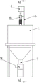
图1为本实用新型的三维立体结构示意图;Fig. 1 is the three-dimensional structure schematic diagram of the present utility model;
图2为本实用新型图1的右视图结构示意图;Fig. 2 is the right view structural representation of Fig. 1 of the utility model;
图3为本实用新型图2中沿A-A处剖视结构示意图;Fig. 3 is the schematic diagram of the cross-sectional structure along A-A in Fig. 2 of the utility model;
图4为本实用新型图3的等轴测立体视角结构示意图;Fig. 4 is a structural schematic diagram of the isometric perspective of Fig. 3 of the utility model;
图5为本实用新型控制机构的部分零件结构示意图。Fig. 5 is a structural schematic diagram of some parts of the control mechanism of the present invention.
图中:1、混料罐;2、安装轴;3、入料箱;4、电机;5、电机架;7、下料管道;8、安装圆柱;9、存放箱;10、伸缩杆;12、不完全齿轮;13、搅拌棒;14、安装板;15、硬毛刷;16、过滤网;17、刮刷;18、蜗杆;19、限位柱。In the figure: 1. Mixing tank; 2. Installation shaft; 3. Feeding box; 4. Motor; 12. Incomplete gear; 13. Stirring rod; 14. Mounting plate; 15. Hard brush; 16. Filter screen; 17. Scraping brush; 18. Worm; 19. Limiting column.
具体实施方式Detailed ways
下面将结合本实用新型实施例中的附图,对本实用新型实施例中的技术方案进行清楚、完整地描述,显然,所描述的实施例仅仅是本实用新型一部分实施例,而不是全部的实施例。基于本实用新型中的实施例,本领域普通技术人员在没有做出创造性劳动前提下所获得的所有其他实施例,都属于本实用新型保护的范围。The technical solutions in the embodiments of the present invention will be clearly and completely described below in conjunction with the accompanying drawings in the embodiments of the present invention. Obviously, the described embodiments are only part of the embodiments of the present invention, not all of them. example. Based on the embodiments of the present utility model, all other embodiments obtained by persons of ordinary skill in the art without making creative efforts belong to the scope of protection of the present utility model.
请参阅图1至图5,本实用新型提供一种技术方案:一种液态饲料喂料线的清洗装置,包括混料罐1和下料管道7,其中,下料管道7连通在混料罐1 的底部,混料罐1的顶部贯穿有可转动和上下滑动的安装轴2,位于混料罐1 内部安装轴2的外壁从上至下固定连接有多组搅拌组件,搅拌组件包括呈圆周阵列固定连接安装轴2外壁上的多个搅拌棒13,安装轴2的底部固定连接有刮刷17,刮刷17能够伸入下料管道7的内部并对下料管道7的内壁进行清刷,混料罐1的顶部设置有驱动安装轴2转动且上下往复移动的控制机构。Please refer to Figures 1 to 5, the utility model provides a technical solution: a cleaning device for a liquid feed feeding line, including a
其中,当水料和饲料在安装轴2的内部进行搅拌混匀呈液态饲料后,会通过下料管道7向外部排出,从而能够使将液态饲料输送至各个喂食口,但是此处是最易发生堵塞的部分,下料管道7的内壁会出现一些颗粒状的软性阻拦饲料,因此需要对下料管道7的内壁进行清理。Among them, when the water and feed are stirred and mixed inside the
当控制机构驱动安装轴2转动的同时上下往复移动时,通过设置多个从上至下安装的搅拌组件,使得多个搅拌棒13能够在对混料罐1内部的溶液进行充分的搅拌,防止搅拌不充分导致液态饲料会堵塞下料管道7,且搅拌组件在搅拌的同时会上下往复移动,从而能够更好对安装轴2内部的液态饲料进行搅拌。When the control mechanism drives the
于此同时,刮刷17的运动形式跟随安装轴2,使得刮刷17能够对下料管道7的内壁进行上下摩擦式的清刷,且由于刮刷17还会持续的转动,从而能够形成一种螺旋向下和螺旋向上的清刷方式,继而能够将内壁的液态饲料的堵塞物进行疏通。At the same time, the movement form of the
进一步地,控制机构包括电机架5,电机架5的顶部固定连接有电机4,电机4的输出端固定连接有伸缩杆10,伸缩杆10的输出端固定连接有安装圆柱8,电机架5的外壁转动连接有限位柱19,安装圆柱8的外壁开设有首尾相连的传动槽,限位柱19的一端伸入传动槽中且与槽内壁滑动连接,安装圆柱8的底部与安装轴2固定连接。Further, the control mechanism includes a motor frame 5, the top of the motor frame 5 is fixedly connected with a
如图3和图5所示,当电机4转动时,能够驱动伸缩杆10和安装圆柱8 转动,当安装圆柱8转动时,由于限位柱19的限位作用,使得安装圆柱8会拉动伸缩杆10在旋转的同时能够上下往复滑动,因此,安装轴2可以在转动的同时上下滑动,在此过程中,伸缩杆10处于连接件的作用,当安装圆柱8 向下运动的过程会使伸缩杆10向下伸长,当安装圆柱8向上运动的过程会使伸缩杆10向上收缩。As shown in Figure 3 and Figure 5, when the
进一步地,位于安装圆柱8下方安装轴2的外壁固定来接有蜗杆18,混料罐1的顶部固定连接入料箱3,入料箱3的底部与混料罐1的内部连通,入料箱3的内壁转动连接有不完全齿轮12,不完全齿轮12包括两个齿牙段,其中一个齿牙段暴露在入料箱3的外部,且暴露在外的齿牙端与蜗杆18啮合连接,另一个齿牙段与入料箱3的内壁贴合,当不完全齿轮12往复小角度转动时能够将位于入料箱3内部的饲料向下疏导。Further, the outer wall of the
当安装轴2在运动的同时,通过两个齿牙段的配合,会使不完全齿轮12 进行往复的转动,同时可以对入料箱3内部的饲料进行一定程度的波动,同时还会对入料箱3内部的饲料进行向下的疏通和导向。When the
进一步地,混料罐1的内壁固定连接有过滤网16,过滤网16位于最下方的搅拌组件的下方,安装轴2的外壁固定连接有多个安装板14,多个安装板 14的底部均固定连接有硬毛刷15,当安装板14位于最高点时,硬毛刷15的底端与过滤网16的顶部相接触。Further, the inner wall of the
当安装轴2在运动的同时,会带动安装板14同步运动,因此,硬毛刷15 会对过滤网16的顶部进行一定程度的清洁,当安装轴2带动安装板14向下移动的同时,硬毛刷15会对过滤网16的顶部造成一定程度的压力,从而更好的对过滤网16的顶部和网孔进行清洁。When the
进一步地,下料管道7的底部连通有存放箱9,存放箱9的外壁设置有多个与其内部连通的输送管道,通过下料管道7和存放箱9的配合,能够将混料罐1中的液体饲料输送至各个喂食口。Further, the bottom of the
进一步地,混料罐1的顶部开设有进水孔,便于向内部进行注水。Further, a water inlet hole is opened on the top of the
进一步地,混料罐1的外壁固定连接卡环,卡环的底部固定连接有多个支撑腿。Further, the outer wall of the
综上,本实用新型能够对充分的对液态饲料进行搅拌,同时对下料管道7 的内壁进行一定程度的清理,防止液态饲料造成下料管道7的堵塞,同时减缓饲料的进料速度,防止影响搅拌的效率。In summary, the utility model can fully stir the liquid feed, and at the same time, clean the inner wall of the
本实施例中使用的标准零件可以从市场上直接购买,而根据说明书和附图的记载的非标准结构部件,也可以直根据现有的技术常识毫无疑义的加工得到,同时各个零部件的连接方式采用现有技术中成熟的常规手段,而机械、零件及设备均采用现有技术中常规的型号,故在此不再作出具体叙述。The standard parts used in this embodiment can be directly purchased from the market, and the non-standard structural parts according to the instructions and drawings can also be processed without any doubt based on existing technical common sense. The connection method adopts mature conventional means in the prior art, and the machinery, parts and equipment all adopt the conventional models in the prior art, so no specific description is made here.
尽管已经示出和描述了本实用新型的实施例,对于本领域的普通技术人员而言,可以理解在不脱离本实用新型的原理和精神的情况下可以对这些实施例进行多种变化、修改、替换和变型,本实用新型的范围由所附权利要求及其等同物限定。Although the embodiments of the present invention have been shown and described, it will be understood by those skilled in the art that various changes and modifications can be made to these embodiments without departing from the principles and spirit of the present invention , alternatives and modifications, the scope of the present invention is defined by the appended claims and their equivalents.
Claims (7)
Priority Applications (1)
| Application Number | Priority Date | Filing Date | Title |
|---|---|---|---|
| CN202123298880.XU CN217657608U (en) | 2021-12-25 | 2021-12-25 | Belt cleaning device of liquid feed line |
Applications Claiming Priority (1)
| Application Number | Priority Date | Filing Date | Title |
|---|---|---|---|
| CN202123298880.XU CN217657608U (en) | 2021-12-25 | 2021-12-25 | Belt cleaning device of liquid feed line |
Publications (1)
| Publication Number | Publication Date |
|---|---|
| CN217657608U true CN217657608U (en) | 2022-10-28 |
Family
ID=83728147
Family Applications (1)
| Application Number | Title | Priority Date | Filing Date |
|---|---|---|---|
| CN202123298880.XU Expired - Fee Related CN217657608U (en) | 2021-12-25 | 2021-12-25 | Belt cleaning device of liquid feed line |
Country Status (1)
| Country | Link |
|---|---|
| CN (1) | CN217657608U (en) |
Cited By (1)
| Publication number | Priority date | Publication date | Assignee | Title |
|---|---|---|---|---|
| CN117380517A (en) * | 2023-11-29 | 2024-01-12 | 安徽省蒙城县恒瑞面粉有限公司 | An anti-clogging feed screening equipment for flour processing |
-
2021
- 2021-12-25 CN CN202123298880.XU patent/CN217657608U/en not_active Expired - Fee Related
Cited By (1)
| Publication number | Priority date | Publication date | Assignee | Title |
|---|---|---|---|---|
| CN117380517A (en) * | 2023-11-29 | 2024-01-12 | 安徽省蒙城县恒瑞面粉有限公司 | An anti-clogging feed screening equipment for flour processing |
Similar Documents
| Publication | Publication Date | Title |
|---|---|---|
| CN210999381U (en) | A concrete mixer with its own cleaning function | |
| CN218111379U (en) | Little plastic preprocessing device convenient to clearance soil | |
| CN208497312U (en) | A kind of self-cleaning concrete mixer | |
| CN108902278A (en) | The wash bowl of razor clam is cleaned in a kind of aquaculture in batches | |
| CN216935628U (en) | A kind of compound water retention agent stirring and mixing device | |
| CN211133944U (en) | A kind of reaction device for preparing Grignard alcohol | |
| CN218797754U (en) | Rice cleaning mechanism for rice flour processing | |
| CN111589785A (en) | An environmentally friendly seed cleaning device | |
| CN220297556U (en) | A mixing device for plastic particles | |
| CN118083205B (en) | Paste material constant temperature filling equipment | |
| CN221156479U (en) | High-speed mixed bed resin mixing device | |
| CN220514897U (en) | Hu sheep forage earth washing tank | |
| CN219399715U (en) | Anti-blocking device for DMC filter residues | |
| CN216537953U (en) | Mixing apparatus is used in water paint processing | |
| CN218959750U (en) | Poultry trough | |
| CN114349552B (en) | Based on ecological breed of cattle farm is with environmental protection fermentation system | |
| CN115815211A (en) | A raw material cleaning machine for processing health-care trotter powder | |
| CN210732838U (en) | Concrete mixer truck concrete waste material scraping device | |
| CN223393385U (en) | Broiler feed batching mixing device | |
| CN222567397U (en) | Feeding equipment | |
| CN114391483B (en) | Pig farm manger convenient to clearance | |
| CN118454622B (en) | Stirring reaction kettle for rubber production and method for producing rubber from tar | |
| CN218303041U (en) | A convenient mixing pesticide sprayer | |
| CN208372899U (en) | A kind of penkeeping agitating device | |
| CN222396597U (en) | Feeding machine is bred to live pig |
Legal Events
| Date | Code | Title | Description |
|---|---|---|---|
| GR01 | Patent grant | ||
| GR01 | Patent grant | ||
| CF01 | Termination of patent right due to non-payment of annual fee |
Granted publication date: 20221028 |
|
| CF01 | Termination of patent right due to non-payment of annual fee |