CN217648686U - Wall body slotting device with dust removal and drying functions for decoration construction - Google Patents
Wall body slotting device with dust removal and drying functions for decoration construction Download PDFInfo
- Publication number
- CN217648686U CN217648686U CN202220578149.8U CN202220578149U CN217648686U CN 217648686 U CN217648686 U CN 217648686U CN 202220578149 U CN202220578149 U CN 202220578149U CN 217648686 U CN217648686 U CN 217648686U
- Authority
- CN
- China
- Prior art keywords
- dust
- screws
- fixed
- shaft sleeve
- slotting device
- Prior art date
- Legal status (The legal status is an assumption and is not a legal conclusion. Google has not performed a legal analysis and makes no representation as to the accuracy of the status listed.)
- Expired - Fee Related
Links
Images
Landscapes
- Processing Of Stones Or Stones Resemblance Materials (AREA)
Abstract
本实用新型公开了一种装饰施工用具有除尘降燥功能墙体开槽装置,包括集尘箱,所述集尘箱上设置有底座与立柱,所述底座通过螺丝安装固定于集尘箱底部,底座底部两侧通过螺丝安装固定有滑轮,所述立柱通过螺丝安装固定于集尘箱顶部中间,立柱上套装有轴套,所述轴套上设置有把手、紧定螺丝与防护罩,所述把手通过螺丝安装固定于轴套后端,所述紧定螺丝通过螺纹连接于轴套左端,所述防护罩通过螺丝安装固定于轴套前端。本实用新型可在墙体开槽时对粉尘进行吸取收集,有效避免了粉尘污染。
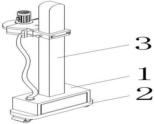
The utility model discloses a wall slotting device with functions of dust removal and drying for decoration construction, comprising a dust collecting box, a base and a column are arranged on the dust collecting box, and the base is installed and fixed on the bottom of the dust collecting box by screws , pulleys are installed and fixed on both sides of the bottom of the base by screws, the column is fixed in the middle of the top of the dust box by screws, and a shaft sleeve is sleeved on the column. The handle is installed and fixed to the rear end of the shaft sleeve by screws, the set screw is connected to the left end of the shaft sleeve by threads, and the protective cover is installed and fixed to the front end of the shaft sleeve by screws. The utility model can absorb and collect the dust when the wall is slotted, thereby effectively avoiding dust pollution.
Description
技术领域technical field
本实用新型涉及一种装饰施工用具有除尘降燥功能墙体开槽装置,属于装饰施工工具技术领域。The utility model relates to a wall slotting device with functions of dust removal and drying for decoration construction, which belongs to the technical field of decoration construction tools.
背景技术Background technique
装修布线时需要对墙体进行开槽操作,而开槽施工时,会产生大量粉尘,不仅污染环境,且严重危害施工人员的健康。为解决上述问题,特提供一种新的技术方案。When decorating and wiring, the wall needs to be slotted, and during slotting construction, a large amount of dust will be generated, which not only pollutes the environment, but also seriously endangers the health of construction workers. In order to solve the above problems, a new technical solution is provided.
发明内容SUMMARY OF THE INVENTION
本实用新型的目的在于提供一种装饰施工用具有除尘降燥功能墙体开槽装置,以解决上述背景技术中提出的问题。The purpose of the present utility model is to provide a wall slotting device with dust removal and drying function for decoration construction, so as to solve the problems raised in the above background technology.
为实现上述目的本实用新型采用以下技术方案:一种装饰施工用具有除尘降燥功能墙体开槽装置,包括集尘箱,所述集尘箱上设置有底座与立柱,所述底座通过螺丝安装固定于集尘箱底部,底座底部两侧通过螺丝安装固定有滑轮,所述立柱通过螺丝安装固定于集尘箱顶部中间,立柱上套装有轴套,所述轴套上设置有把手、紧定螺丝与防护罩,所述把手通过螺丝安装固定于轴套后端,所述紧定螺丝通过螺纹连接于轴套左端,所述防护罩通过螺丝安装固定于轴套前端。In order to achieve the above purpose, the utility model adopts the following technical solutions: a wall slotting device with dust removal and drying function for decoration construction, including a dust collecting box, a base and a column are arranged on the dust collecting box, and the base is screwed through screws. It is installed and fixed at the bottom of the dust collecting box, and the two sides of the bottom of the base are fixed with pulleys by screws. A set screw and a protective cover, the handle is installed and fixed to the rear end of the shaft sleeve by screws, the set screw is connected to the left end of the shaft sleeve by threads, and the protective cover is installed and fixed to the front end of the shaft sleeve by screws.
优选的,所述防护罩顶部与底部通过螺丝对称安装固定有吸尘罩,所述吸尘罩上设置有吸尘口与电机,所述吸尘口开设于吸尘罩右侧前端,所述电机通过螺丝安装固定于上方的吸尘罩顶部。Preferably, the top and bottom of the protective cover are symmetrically installed and fixed with a dust hood, the dust hood is provided with a dust suction port and a motor, the dust suction port is opened at the front end of the right side of the dust hood, and the The motor is fixed to the top of the dust cover above by means of screws.
优选的,所述电机主轴贯穿并延伸至吸尘罩内部通过螺丝安装固定有主齿轮,所述主齿轮后端啮合连接有从动齿轮,所述从动齿轮通过轴承与吸尘罩内壁过盈连接,且从动齿轮内端面通过螺丝安装固定有吸尘扇叶。Preferably, the main shaft of the motor penetrates and extends to the inside of the dust hood, and a main gear is installed and fixed with screws, and the rear end of the main gear is meshed and connected with a driven gear, and the driven gear interferes with the inner wall of the dust hood through a bearing. connected, and the inner end face of the driven gear is fixed with a vacuum fan blade by means of screws.
优选的,所述主齿轮内端面之间通过螺丝安装固定有切割锯片,所述切割锯片放置于防护罩内部前端。Preferably, a cutting saw blade is installed and fixed between the inner end faces of the main gear by screws, and the cutting saw blade is placed at the inner front end of the protective cover.
优选的,所述吸尘罩通过管道与集尘箱管连接。Preferably, the dust hood is connected to the dust collecting box pipe through a pipe.
与现有技术相比,本实用新型的有益效果是:本实用新型底座底部两侧通过螺丝安装固定有滑轮,可使集尘箱轻松进行移动;立柱上套装有轴套,可通过轴套轻松带动防护罩顺着立柱上下直线滑动;主齿轮内端面之间通过螺丝安装固定有切割锯片,可通过电机轻松带动主齿轮与切割锯片同时进行旋转;主齿轮后端啮合连接有从动齿轮,可通过主齿轮轻松带动吸尘扇叶进行旋转;综合上述本实用新型可在墙体开槽时对粉尘进行吸取收集,有效避免了粉尘污染。Compared with the prior art, the beneficial effects of the present utility model are: pulleys are installed and fixed on both sides of the bottom of the base of the utility model by screws, so that the dust collecting box can be easily moved; Drive the protective cover to slide straight up and down along the vertical column; the inner end face of the main gear is fixed with a cutting saw blade by screws, and the main gear and the cutting saw blade can be easily driven to rotate at the same time by the motor; the rear end of the main gear is meshed and connected with a driven gear , the dust suction fan blade can be easily driven to rotate through the main gear; the above-mentioned utility model can absorb and collect dust when the wall is slotted, thereby effectively avoiding dust pollution.
附图说明Description of drawings
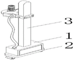
图1为本实用新型结构示意图;Fig. 1 is the structural representation of the utility model;
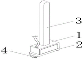
图2为本实用新型集尘箱结构示意图;Fig. 2 is the structural schematic diagram of the dust collecting box of the present utility model;
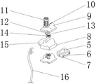
图3为本实用新型防护罩结构示意图;3 is a schematic structural diagram of a protective cover of the present invention;
图中:1-集尘箱;2-底座;3-立柱;4-滑轮;5-轴套;6-把手;7-紧定螺丝;8-防护罩;9-吸尘罩;10-吸尘口;11-电机;12-主齿轮;13-从动齿轮;14-吸尘扇叶;15-切割锯片;16-管道。In the picture: 1-dust box; 2-base; 3-post; 4-pulley; 5-sleeve; 6-handle; 7-set screw; 8-protective cover; 9-dust cover; 10-suction Dust port; 11-motor; 12-main gear; 13-driven gear; 14-dust suction fan blade; 15-cutting saw blade; 16-pipe.
具体实施方式Detailed ways
下面将结合本实用新型实施例中的附图,对本实用新型实施例中的技术方案进行清楚、完整的阐述。The technical solutions in the embodiments of the present utility model will be clearly and completely described below with reference to the accompanying drawings in the embodiments of the present utility model.
如图1-3所示,一种装饰施工用具有除尘降燥功能墙体开槽装置,包括集尘箱1,所述集尘箱1上设置有底座2与立柱3,底座2通过螺丝安装固定于集尘箱1底部,底座2底部两侧通过螺丝安装固定有滑轮4,立柱3通过螺丝安装固定于集尘箱1顶部中间,立柱3上套装有轴套5,轴套5上设置有把手6、紧定螺丝7与防护罩8,把手6通过螺丝安装固定于轴套5后端,紧定螺丝7通过螺纹连接于轴套5左端,防护罩8通过螺丝安装固定于轴套5前端,防护罩8顶部与底部通过螺丝对称安装固定有吸尘罩9,吸尘罩9上设置有吸尘口10与电机11,吸尘口10开设于吸尘罩9右侧前端,电机11通过螺丝安装固定于上方的吸尘罩9顶部,电机11主轴贯穿并延伸至吸尘罩9内部通过螺丝安装固定有主齿轮12,主齿轮12后端啮合连接有从动齿轮13,从动齿轮13通过轴承与吸尘罩9内壁过盈连接,且从动齿轮13内端面通过螺丝安装固定有吸尘扇叶14,主齿轮12内端面之间通过螺丝安装固定有切割锯片15,切割锯片15放置于防护罩8内部前端,吸尘罩9通过管道16与集尘箱1管连接。As shown in Figures 1-3, a wall slotting device with dust removal and drying function for decorative construction includes a
具体使用方式:需要对墙体进行开槽操作时,根据施工高度通过紧定螺丝7对轴套5的高度进行锁定,随后开启电机11带动主齿轮12与切割锯片15同时进行旋转,切割锯片15旋转对墙体进行切割开槽操作,主齿轮12旋转带动从动齿轮13进行旋转,从动齿轮13旋转带动吸尘扇叶14旋转,吸尘扇叶14旋转通过吸尘口10对开槽时所产生的粉尘进行吸取;同时滑轮4可使切割锯片15顺着地面或墙体直线移动,有效保证了槽口的水平度。Specific use method: when the wall needs to be slotted, the height of the
以上所述为本实用新型较佳实施例,对于本领域的普通技术人员而言,根据本实用新型的教导,在不脱离本实用新型的原理与精神的情况下,对实施方式所进行的改变、修改、替换和变型仍落入本实用新型的保护范围之内。The above are the preferred embodiments of the present invention. For those of ordinary skill in the art, according to the teachings of the present invention, without departing from the principles and spirit of the present invention, the changes to the embodiments can be made. , modification, replacement and modification still fall within the protection scope of the present invention.
Claims (5)
Priority Applications (1)
| Application Number | Priority Date | Filing Date | Title |
|---|---|---|---|
| CN202220578149.8U CN217648686U (en) | 2022-03-17 | 2022-03-17 | Wall body slotting device with dust removal and drying functions for decoration construction |
Applications Claiming Priority (1)
| Application Number | Priority Date | Filing Date | Title |
|---|---|---|---|
| CN202220578149.8U CN217648686U (en) | 2022-03-17 | 2022-03-17 | Wall body slotting device with dust removal and drying functions for decoration construction |
Publications (1)
| Publication Number | Publication Date |
|---|---|
| CN217648686U true CN217648686U (en) | 2022-10-25 |
Family
ID=83661756
Family Applications (1)
| Application Number | Title | Priority Date | Filing Date |
|---|---|---|---|
| CN202220578149.8U Expired - Fee Related CN217648686U (en) | 2022-03-17 | 2022-03-17 | Wall body slotting device with dust removal and drying functions for decoration construction |
Country Status (1)
| Country | Link |
|---|---|
| CN (1) | CN217648686U (en) |
Cited By (2)
| Publication number | Priority date | Publication date | Assignee | Title |
|---|---|---|---|---|
| CN116377820A (en) * | 2023-03-13 | 2023-07-04 | 中建八局第二建设有限公司 | Self-cleaning slotting machine and construction method |
| CN116423675A (en) * | 2023-03-24 | 2023-07-14 | 徐州振丰新型墙体材料有限公司 | Wall body production cutting device |
-
2022
- 2022-03-17 CN CN202220578149.8U patent/CN217648686U/en not_active Expired - Fee Related
Cited By (2)
| Publication number | Priority date | Publication date | Assignee | Title |
|---|---|---|---|---|
| CN116377820A (en) * | 2023-03-13 | 2023-07-04 | 中建八局第二建设有限公司 | Self-cleaning slotting machine and construction method |
| CN116423675A (en) * | 2023-03-24 | 2023-07-14 | 徐州振丰新型墙体材料有限公司 | Wall body production cutting device |
Similar Documents
| Publication | Publication Date | Title |
|---|---|---|
| CN214867539U (en) | Dust collector is used in milling machine processing | |
| CN208529440U (en) | A kind of ceramic tile cutter with dedusting function | |
| CN211248520U (en) | A kind of plate shearing machine for processing railway pier body formwork | |
| CN210126135U (en) | Wood chip recovery device for wood board processing | |
| CN217833047U (en) | Polishing device for metal ceramic cutter | |
| CN210113015U (en) | Dustless no dead angle plane wall planer | |
| CN108972909B (en) | Hydroelectric grooving machine for indoor decoration | |
| CN220533855U (en) | Wood-plastic wallboard face burnishing device | |
| CN218891666U (en) | Non-ferrous metal inner and outer surface polishing machine | |
| CN208069235U (en) | A kind of engraving machine main shaft dust cover | |
| CN214519249U (en) | A wall grinding device for building decoration and decoration | |
| CN216398215U (en) | A kind of multi-station cutting equipment for hardware precision machining | |
| CN211762157U (en) | A cutting device for wood system toy production | |
| CN210588376U (en) | Automatic cleaning device of workstation for machine tool machining | |
| CN217317237U (en) | Polishing device for copper pipe machining | |
| CN220838195U (en) | Aluminum profile cutting device | |
| CN222154826U (en) | Prevent numerically controlled fraise machine that splashes | |
| CN220296643U (en) | Wall equipment of polishing of decoration fitment | |
| CN222958838U (en) | Main shaft dust raising fan of numerical control engraving machine | |
| CN221290551U (en) | Polishing device for curtain wall plate machining | |
| CN221232193U (en) | Brushless self-dust-suction grinding machine | |
| CN216578312U (en) | High-precision plate cutting saw with saw dust collecting function | |
| CN224209594U (en) | High-efficient grinding device is used in gong groove frame processing | |
| CN222176101U (en) | Mechanical cutting device for mechanical processing | |
| CN220718876U (en) | Sheet metal angle grinder |
Legal Events
| Date | Code | Title | Description |
|---|---|---|---|
| GR01 | Patent grant | ||
| GR01 | Patent grant | ||
| CF01 | Termination of patent right due to non-payment of annual fee | ||
| CF01 | Termination of patent right due to non-payment of annual fee |
Granted publication date: 20221025 |