CN217648080U - Environment-friendly polisher - Google Patents
Environment-friendly polisher Download PDFInfo
- Publication number
- CN217648080U CN217648080U CN202222056142.2U CN202222056142U CN217648080U CN 217648080 U CN217648080 U CN 217648080U CN 202222056142 U CN202222056142 U CN 202222056142U CN 217648080 U CN217648080 U CN 217648080U
- Authority
- CN
- China
- Prior art keywords
- polishing
- dust
- disc
- shell
- environment
- Prior art date
- Legal status (The legal status is an assumption and is not a legal conclusion. Google has not performed a legal analysis and makes no representation as to the accuracy of the status listed.)
- Active
Links
Images


Abstract
The utility model discloses an environment-friendly grinding machine, which comprises a shell and handrails, wherein support legs of the handrails are rotatably arranged at two sides of the shell, a mounting plate is horizontally arranged in the shell, and a grinding basal disc is rotatably arranged below the mounting plate; a fixed disc is arranged above the polishing base disc, a plurality of fixing bolts are connected between the fixed disc and the polishing base disc, the fixed disc is fixedly arranged on the output end of a driving motor, and the driving motor is vertically and fixedly arranged on the inner top wall of the shell; a plurality of polishing sheet fixing grooves are integrally formed on the polishing base disc, and polishing sheets are arranged in the polishing sheet fixing grooves; a plurality of dust exhaust holes are formed in the polishing sheet in an annular distribution mode. The utility model discloses compact structure, reasonable in design, the improvement of very big degree the effect of polishing of polisher has reduced the consumptive material cost that the polisher used, has improved the feature of environmental protection that the polisher used, has also reduced controlling the degree of difficulty of polisher, has guaranteed the adaptability of polisher to different operation surfaces.
Description
Technical Field
The utility model relates to a ground surface equipment technical field that polishes especially relates to an environment-friendly polisher.
Background
The epoxy floor has the advantages of wear resistance, corrosion resistance, low price and the like, is widely used in the construction of functional buildings such as various plants, dust-free workshops, antistatic workshops and underground garages, and needs to polish a base surface during the construction of the epoxy floor so as to ensure the construction quality of the epoxy floor.
Through retrieval, the patent of application number CN201921155678.1 discloses a rod pressing type floor polisher which is suitable for rapidly polishing a floor to a construction standard before the construction of an epoxy floor anticorrosion process. This pole pressure formula terrace polisher includes the frame and sets up the polisher body in its inside, the front end of polisher body with the frame location is connected, the rear end of polisher body sets up the mill, the mill is by depression bar mechanism drive luffing motion, wherein, depression bar mechanism is including setting up support portal on the frame base and with the crossbeam swing joint's of support portal pressure thick stick, the pole body of pressure thick stick is in with the setting the lift jib swing joint of polisher body rear end. This pole pressure formula terrace polisher has the position of polishing of being convenient for observe, real-time adjustment dynamics of polishing and easy operation, efficient characteristics of polishing.
The dust extraction does not have to the above-mentioned device and absorbs the dust that produces when polishing, and the feature of environmental protection is relatively poor to use large-scale mill to polish, the cost of consumptive material is higher, also is inconvenient to be changed the mill, and inconvenient adjusts the truckle, and is relatively poor to the adaptability of operation surface.
SUMMERY OF THE UTILITY MODEL
The utility model aims at solving and exist among the prior art and do not have dust extraction to absorb the dust that produces when polishing, the feature of environmental protection is relatively poor to use large-scale mill to polish, the cost of consumptive material is higher, also is inconvenient to change the mill, and inconvenient adjust the truckle, to the relatively poor shortcoming of operation surface adaptability, and the environment-friendly polisher that provides.
In order to achieve the above purpose, the utility model adopts the following technical scheme:
the utility model provides an environment-friendly polisher, includes shell and handrail, the stabilizer blade of handrail rotates and installs in the shell both sides, the level is equipped with the mounting panel in the shell, and the mounting panel below rotates and is equipped with the base plate of polishing.
The polishing base plate is characterized in that a fixed disc is arranged above the polishing base plate, a plurality of fixing bolts are connected between the fixed disc and the polishing base plate, the fixed disc is fixedly installed at the output end of a driving motor, and the driving motor is vertically and fixedly installed on the inner top wall of the shell.
A plurality of polishing piece fixing grooves are integrally formed in the polishing base plate, and polishing pieces are arranged in the polishing piece fixing grooves.
The base plate of polishing is that the annular distributes and has seted up a plurality of dust exhaust holes, and the dust exhaust hole top is equipped with the negative pressure dust absorption cover, the mounting panel upper end is equipped with stores up the dirt room, and it has the dust absorption pipe to store up to link up between dirt room and the negative pressure dust absorption cover, store up the indoor vertical dust screen that is equipped with of dirt, one side that the dust absorption pipe was kept away from to the dust screen has the mechanism that induced drafts.
Preferably, the mechanism of induced drafting includes the aspiration channel with dust absorption pipe through connection, and the aspiration channel other end is connected with the induction port of suction fan, be equipped with turbine fan blade in the suction fan, turbine fan blade center pin upwards extends and the cover is equipped with driven pulleys, and driven pulleys is connected with driving pulley through the belt, and the fixed cover of driving pulley is established on driving motor's output.
Preferably, the center of the bottom wall of the fixed disc is provided with a triangular positioning pin, the polishing base disc is provided with a triangular positioning hole matched with the triangular positioning pin, the lower end of the triangular positioning pin is provided with a stud with a thread direction opposite to the rotation direction of the polishing base disc, and the stud is in threaded connection with a flange nut used for locking the polishing base disc.
Preferably, the fixed disk outside cover is equipped with the bearing, and the outer lane fixed mounting of bearing is on the mounting panel diapire.
Preferably, the bottom wall of the polishing base disc corresponding to the position of the dust exhaust hole is provided with a plurality of cleaning brush wires in a cluster manner.
Preferably, a closed cover is arranged at the lower part of the side wall of the shell.
Preferably, the inner chamber both sides of shell are equipped with the auxiliary wheel unanimous with the handrail direction, and equal vertical rotation is connected with the traveller on the auxiliary wheel, and traveller outside sliding connection has the sliding sleeve, and the sliding sleeve all link up and install on the shell, all be equipped with locking bolt on the sliding sleeve, be equipped with the spring gasket on the locking bolt, all seted up a plurality of regulation holes corresponding with locking bolt on the traveller.
Compared with the prior art, the beneficial effects of the utility model are that:
1. the polishing machine uses a plurality of polishing sheet fixing grooves to mount and fix the polishing sheets, so that the polishing machine can use smaller polishing sheets to polish in a large area, the polishing efficiency is ensured, and the use cost of the polishing sheets is reduced;
2. the sander absorbs the generated dust during sanding through the suction fan and inhibits the dust in the sander by matching with the sealing cover, so that the dust during sanding is reduced, the environmental protection of construction environment is improved, and the health of constructors is protected;
3. the grinding machine is moved by the auxiliary wheel to assist grinding, so that the grinding machine is guaranteed to move on an expected route, the operation difficulty of the grinding machine is reduced, the grinding quality is improved, and the adaptability of the grinding machine to different operation surfaces is improved by adjusting the auxiliary wheel.
The utility model discloses compact structure, reasonable in design, the improvement of very big degree the effect of polishing of polisher has reduced the consumptive material cost that the polisher used, has improved the feature of environmental protection that the polisher used, has also reduced controlling the degree of difficulty of polisher, has guaranteed the adaptability of polisher to different operation surfaces.
Drawings
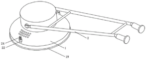
Fig. 1 is a schematic view of an appearance structure of an environment-friendly grinding machine provided by the present invention;
fig. 2 is a schematic front structural view of an environment-friendly grinding machine provided by the present invention;
FIG. 3 is a schematic view of a partial structure of a polishing base plate of the environment-friendly polishing machine of the present invention;
fig. 4 is a schematic view of an appearance structure of a polishing base plate of the environment-friendly polishing machine provided by the utility model;
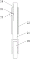
fig. 5 is a schematic view of the auxiliary wheel structure of the environment-friendly grinding machine provided by the present invention.
In the figure: the device comprises a shell 1, a handrail 2, a mounting plate 3, a polishing base plate 4, a triangular positioning hole 41, a polishing piece fixing groove 42, a cleaning brush wire 43, a dust exhaust hole 44, a triangular positioning pin 5, a fixing plate 6, a bearing 7, a driving motor 8, a polishing piece 9, a negative pressure dust collection sleeve 10, a dust collection pipe 11, a dust storage chamber 12, a dust filter screen 13, an air suction pipe 14, an air suction fan 15, a turbine fan blade 16, a driven pulley 17, a driving pulley 18, a sealing cover 19, an auxiliary wheel 20, a sliding column 21, a sliding sleeve 22, a locking bolt 23, an adjusting hole 24 and a spring gasket 25.
Detailed Description
The technical solutions in the embodiments of the present invention will be described clearly and completely with reference to the accompanying drawings in the embodiments of the present invention, and it is obvious that the described embodiments are only some embodiments of the present invention, not all embodiments.
In the description of the present invention, it is to be understood that the terms "upper", "lower", "front", "rear", "left", "right", "top", "bottom", "inner", "outer", and the like indicate orientations or positional relationships based on the orientations or positional relationships shown in the drawings, and are only for convenience of description and simplicity of description, and do not indicate or imply that the device or element being referred to must have a particular orientation, be constructed and operated in a particular orientation, and therefore, should not be construed as limiting the present invention.
Example one
Referring to fig. 1-5, an environment-friendly polisher, includes shell 1 and handrail 2, the stabilizer blade of handrail 2 rotates and installs in shell 1 both sides, makes things convenient for the operating personnel of different sizes to use, also makes things convenient for the transportation of polisher, the level is equipped with mounting panel 3 in the shell 1, and 3 below rotations of mounting panel are equipped with base plate 4 of polishing for polish basic unit or epoxy terrace.
Polishing basal disc 4 top is equipped with fixed disk 6, and fixed disk 6 and polishing are connected with a plurality of fixed screws between the basal disc 4, improve the fixed effect of polishing basal disc 4, guarantee the stability of polishing, fixed disk 6 fixed mounting is on driving motor 8's output, and the vertical fixed mounting of driving motor 8 is on the roof in shell 1.
A plurality of polishing sheet fixing grooves 42 are integrally formed in the polishing base plate 4, and the polishing sheets 9 are arranged in the polishing sheet fixing grooves 42, so that polishing cost is reduced, and large-area polishing can be performed by using the smaller polishing sheets 9. On the other hand makes things convenient for the change of polishing piece 9, avoids the frequent dismouting to polishing basal disc 4, makes things convenient for the polishing piece 9 of installing different functions as required.
It has seted up a plurality of dust exhaust holes 44 to be the annular distribution on the base disc 4 to polish, absorbs the dust that grinds the production, guarantees the environmental protection requirement of construction, reduces the raise dust of polishing, and dust exhaust hole 44 top is equipped with negative pressure dust absorption cover 10, 3 upper ends of mounting panel are equipped with storage dirt room 12, and through connection has dust absorption pipe 11 between storage dirt room 12 and the negative pressure dust absorption cover 10, the vertical dust screen 13 that is equipped with in the storage dirt room 12, one side through connection that dust absorption pipe 11 was kept away from to dust screen 13 has the mechanism of induced drafting, and the raise dust that will polish the production inhales in the storage dirt room 12, makes things convenient for the collection and the processing of raise dust.
When the polisher is used, the polishing base disc 4 is firstly fixedly installed on the fixing disc 6 through fixing screws, the used polishing sheet 9 is installed in the polishing sheet fixing groove 42 according to polishing requirements, and then the polishing sheet 9 can be replaced according to operation requirements.
When using the polisher to polish, driving motor 8 drives 4 rotations of basal disc of polishing, cooperation polishing piece 9 polishes the operation surface, cooperation handrail 2 promotes shell 1 and polishes, when polishing, driving motor 8 drives turbine fan blade 16 and makes and store up the interior negative pressure effect that produces of dirt room 12, cooperation dust exhaust hole 44 absorbs the dust that produces of polishing, the raise dust of avoiding polishing the production influences the construction effect, also improve the feature of environmental protection that the polisher used, protection operating personnel's health.
In this embodiment, as shown in fig. 2-3, the air suction mechanism includes an air suction pipe 14 connected to the dust suction pipe 11, an air suction port of an air suction fan 15 is connected to the other end of the air suction pipe 14, a turbine blade 16 is disposed in the air suction fan 15, a central axis of the turbine blade 16 extends upward and is sleeved with a driven pulley 17, the driven pulley 17 is connected to a driving pulley 18 through a belt, the driving pulley 18 is fixedly sleeved on an output end of the driving motor 8, and the dust is sucked by the negative pressure effect generated by the turbine blade 16 in cooperation with the air suction pipe 14, so as to ensure the dust suction effect.
In this embodiment, as shown in fig. 2-4, 6 diapire center departments of fixed disk are equipped with triangle locating pin 5, polish and offer on the base plate 4 with triangle locating pin 5 assorted triangle locating hole 41, 5 lower extremes of triangle locating pin are equipped with the screw thread direction and polish base plate 4 and rotate the double-screw bolt that the opposite direction, and threaded connection has the flange nut who is used for locking base plate 4 of polishing on the double-screw bolt, and through the cooperation of triangle locating pin 5 and triangle locating hole 41, improve driven stability on the one hand, guarantee to polish stable the rotation of base plate 4, on the other hand conveniently polishes the location installation of base plate 4, makes things convenient for the installation of fixed screw, cooperates reverse screw also to avoid polishing the not hard up of base plate 4 rotation in-process flange nut simultaneously.
In this embodiment, as shown in fig. 2 and 3, the bearing 7 is sleeved on the outer side of the fixed disk 6, and the outer ring of the bearing 7 is fixedly mounted on the bottom wall of the mounting plate 3, so that the rotating stability of the fixed disk 6 and the grinding base disk 4 is improved.
In this embodiment, as shown in fig. 2 and 3, a plurality of cleaning brush wires 43 are clustered on the bottom wall of the polishing base plate 4 corresponding to the dust discharge hole 44, so as to clean the polished debris and improve the dust absorption effect.
In this embodiment, as shown in fig. 1 to 3, a sealing cover 19 is disposed on a lower portion of a side wall of the housing 1, so that splashing of chips generated by polishing is avoided, safety of polishing operation is improved, dust is prevented from dispersing, environmental friendliness of the polishing machine is improved, a negative pressure state generated in the polishing machine is facilitated, and a dust collection effect is improved.
Example two
Referring to fig. 1-5, in this embodiment, basically the same as the first embodiment, it is more optimized that auxiliary wheels 20 in the same direction as the handrails 2 are disposed on two sides of the inner cavity of the housing 1, the auxiliary wheels 20 are vertically and rotatably connected to sliding columns 21, sliding sleeves 22 are slidably connected to the outer sides of the sliding columns 21, the sliding sleeves 22 are all installed on the housing 1 in a penetrating manner, locking bolts 23 are disposed on the sliding sleeves 22, spring washers 25 are disposed on the locking bolts 23, and a plurality of adjusting holes 24 corresponding to the locking bolts 23 are disposed on the sliding columns 21.
At the operation in-process of polishing, because the circumstances such as earth's surface inequality when polishing the basal disc 4 and rotate can lead to the polisher not to control well, and the route of marcing is unstable, and the influence is to the effect of polishing on basic unit ground, and cooperation auxiliary wheel 20 can provide certain side direction holding power, reduces the operation degree of difficulty of polisher, improves the result of use of polisher.
The height of adjusting traveller 21 and auxiliary wheel 20 is adjusted to cooperation regulation hole 24, and the supplementary effect of auxiliary wheel 20 is adjusted according to the in service behavior of reality to the improvement is to the adaptability on different operation surfaces, and cooperation spring shim 25 also can effectually avoid under vibrations locking bolt 23 not hard up, guarantees the stability that auxiliary wheel 20 used.
The above, only be the concrete implementation of the preferred embodiment of the present invention, but the protection scope of the present invention is not limited thereto, and any person skilled in the art is in the technical scope of the present invention, according to the technical solution of the present invention and the utility model, the concept of which is equivalent to replace or change, should be covered within the protection scope of the present invention.
Claims (7)
1. An environment-friendly grinding machine comprises a shell (1) and armrests (2), and is characterized in that supporting legs of the armrests (2) are rotatably installed on two sides of the shell (1), an installation plate (3) is horizontally arranged in the shell (1), and a grinding base disc (4) is rotatably arranged below the installation plate (3);
a fixed disc (6) is arranged above the polishing base disc (4), a plurality of fixing bolts are connected between the fixed disc (6) and the polishing base disc (4), the fixed disc (6) is fixedly arranged on the output end of a driving motor (8), and the driving motor (8) is vertically and fixedly arranged on the inner top wall of the shell (1);
a plurality of polishing sheet fixing grooves (42) are integrally formed on the polishing base disc (4), and polishing sheets (9) are arranged in the polishing sheet fixing grooves (42);
it has seted up a plurality of dust exhaust holes (44) to be annular distribution on base plate (4) of polishing, is equipped with negative pressure dust absorption cover (10) above dust exhaust hole (44), mounting panel (3) upper end is equipped with stores up dirt room (12), and through connection has dust absorption pipe (11) between dust storage room (12) and negative pressure dust absorption cover (10), vertical dust screen (13) that are equipped with in dust storage room (12), one side through connection that dust absorption pipe (11) were kept away from in dust screen (13) has the mechanism of induced drafting.
2. The environment-friendly grinding machine according to claim 1, wherein the air suction mechanism comprises an air suction pipe (14) communicated with the dust suction pipe (11), the other end of the air suction pipe (14) is connected with an air suction port of an air suction fan (15), a turbine blade (16) is arranged in the air suction fan (15), a central shaft of the turbine blade (16) extends upwards and is sleeved with a driven pulley (17), the driven pulley (17) is connected with a driving pulley (18) through a belt, and the driving pulley (18) is fixedly sleeved on an output end of the driving motor (8).
3. The environment-friendly grinding machine according to claim 1, characterized in that a triangular positioning pin (5) is arranged at the center of the bottom wall of the fixed disc (6), a triangular positioning hole (41) matched with the triangular positioning pin (5) is formed in the grinding base disc (4), a stud with a thread direction opposite to the rotation direction of the grinding base disc (4) is arranged at the lower end of the triangular positioning pin (5), and a flange nut used for locking the grinding base disc (4) is connected to the stud in a threaded manner.
4. An environment-friendly sander according to claim 1, characterized in that a bearing (7) is sleeved outside the fixed disc (6), and the outer ring of the bearing (7) is fixedly mounted on the bottom wall of the mounting plate (3).
5. An environment-friendly grinding machine as claimed in claim 1, characterized in that a plurality of cleaning brush filaments (43) are arranged in clusters on the bottom wall of the grinding base disc (4) corresponding to the positions of the dust exhaust holes (44).
6. An environment-friendly sanding machine according to claim 1, characterized in that the lower part of the side wall of the housing (1) is provided with a closing hood (19).
7. The environment-friendly grinding machine according to claim 1, characterized in that auxiliary wheels (20) with the same direction as the armrest (2) are arranged on two sides of an inner cavity of the housing (1), the auxiliary wheels (20) are vertically and rotatably connected with sliding columns (21), sliding sleeves (22) are slidably connected to the outer sides of the sliding columns (21), the sliding sleeves (22) are all installed on the housing (1) in a penetrating manner, locking bolts (23) are arranged on the sliding sleeves (22), spring washers (25) are arranged on the locking bolts (23), and a plurality of adjusting holes (24) corresponding to the locking bolts (23) are formed in the sliding columns (21).
Priority Applications (1)
| Application Number | Priority Date | Filing Date | Title |
|---|---|---|---|
| CN202222056142.2U CN217648080U (en) | 2022-08-05 | 2022-08-05 | Environment-friendly polisher |
Applications Claiming Priority (1)
| Application Number | Priority Date | Filing Date | Title |
|---|---|---|---|
| CN202222056142.2U CN217648080U (en) | 2022-08-05 | 2022-08-05 | Environment-friendly polisher |
Publications (1)
| Publication Number | Publication Date |
|---|---|
| CN217648080U true CN217648080U (en) | 2022-10-25 |
Family
ID=83688271
Family Applications (1)
| Application Number | Title | Priority Date | Filing Date |
|---|---|---|---|
| CN202222056142.2U Active CN217648080U (en) | 2022-08-05 | 2022-08-05 | Environment-friendly polisher |
Country Status (1)
| Country | Link |
|---|---|
| CN (1) | CN217648080U (en) |
-
2022
- 2022-08-05 CN CN202222056142.2U patent/CN217648080U/en active Active
Similar Documents
| Publication | Publication Date | Title |
|---|---|---|
| CN209304228U (en) | A kind of floor polishers | |
| CN217648080U (en) | Environment-friendly polisher | |
| CN210255421U (en) | Adjustable cylindrical grinding machine | |
| CN211867336U (en) | A sweep ray apparatus for cell-phone tempering membrane | |
| CN213592442U (en) | Concrete floor terrazzo machine for building construction | |
| CN214054706U (en) | Full-automatic edging processingequipment of toughened glass | |
| CN214519593U (en) | Dustproof device of polishing table | |
| CN211661693U (en) | Efficient is grinder for terrace coating | |
| CN210081363U (en) | Efficient and easy-to-operate glass edge grinding device | |
| CN114012565A (en) | Sealing member processing agency | |
| CN210024797U (en) | Stone material grinding device for building site | |
| CN112571209A (en) | Combinable and detachable polishing machine | |
| CN213195915U (en) | Numerical control cutting machine is used in processing of car baking finish room | |
| CN2675337Y (en) | Sander | |
| CN213165586U (en) | Production line for damping plate | |
| CN216265228U (en) | Special grinding device of steel for house building | |
| CN211388070U (en) | Helmet deckle edge polisher | |
| CN219747304U (en) | Surface grinding machine with dustproof function | |
| CN217991992U (en) | Carbide tool bar grinding device with adsorb and collect structure | |
| CN219189848U (en) | Stone polishing machine | |
| CN219337099U (en) | Novel grinding machine for wall construction | |
| CN219358933U (en) | Wall grinding device | |
| CN219212645U (en) | Polishing equipment | |
| CN212351570U (en) | Dustproof circular arc burnishing machine | |
| CN218927282U (en) | Construction equipment of hydraulic engineering |
Legal Events
| Date | Code | Title | Description |
|---|---|---|---|
| GR01 | Patent grant | ||
| GR01 | Patent grant |