CN217647465U - Stainless steel flange forging mould - Google Patents
Stainless steel flange forging mould Download PDFInfo
- Publication number
- CN217647465U CN217647465U CN202221537159.3U CN202221537159U CN217647465U CN 217647465 U CN217647465 U CN 217647465U CN 202221537159 U CN202221537159 U CN 202221537159U CN 217647465 U CN217647465 U CN 217647465U
- Authority
- CN
- China
- Prior art keywords
- membrane shell
- arc
- stainless steel
- die
- shell
- Prior art date
- Legal status (The legal status is an assumption and is not a legal conclusion. Google has not performed a legal analysis and makes no representation as to the accuracy of the status listed.)
- Active
Links
Images


Landscapes
- Forging (AREA)
Abstract
The utility model relates to the technical field of mold, especially, relate to a stainless steel flange forging mould, including lower membrane shell and last membrane shell, lower membrane shell and last membrane shell activity card are in the same place, be provided with actuating mechanism down between membrane shell and the last membrane shell, be provided with isolated mechanism down in membrane shell and the last membrane shell, isolated mechanism includes the hydro-cylinder, fixed mounting has the rectangle connecting plate on the telescopic link of hydro-cylinder, the lower fixed surface of rectangle connecting plate installs the round bar, fixed mounting has the arc below the round bar, the arc has been seted up on membrane shell and the last membrane shell down, arc activity card is in the arc, be provided with the cutting ring of bolt installation on the arc, the utility model discloses a controlling reciprocating of arc, letting reciprocating of arc drive reciprocating of cutting ring, cutting solution to let form complete circular flange, thereby improve the shaping effect of flange.
Description
Technical Field
The utility model relates to the technical field of mold, especially, relate to a stainless steel flange forging mould.
Background
Moulds (Mule) are used for obtaining various moulds and tools of required products by injection moulding, blow moulding, extrusion, die casting or forging forming, smelting, stamping and other methods in industrial production. In short, a mold is a tool used to make a shaped article, the tool being made up of various parts, different molds being made up of different parts. The processing of the appearance of an article is realized mainly through the change of the physical state of a formed material. The element has the name of "industrial mother".
The blank is formed into a tool with a specific shape and size under the action of external force. The method is widely applied to blanking, die forging, cold heading, extrusion, powder metallurgy part pressing, pressure casting and the forming processing of compression molding or injection molding of products such as engineering plastics, rubber, ceramics and the like. The die has a specific contour or cavity shape, and the blank can be separated (blanked) according to the contour shape by applying the contour shape with the cutting edge. The blank can obtain a corresponding three-dimensional shape by using the shape of the inner cavity. The mold generally comprises a movable mold and a fixed mold (or a male mold and a female mold), which can be separated or combined. When the blank is closed, the blank is injected into the die cavity for forming. The die is a precise tool, has a complex shape, bears the expansion force of a blank, has higher requirements on structural strength, rigidity, surface hardness, surface roughness and processing precision, and the development level of die production is one of important marks of the mechanical manufacturing level.
As disclosed in the chinese patent: a mold, publication No.: CN208359407U uses the technical scheme of the utility model, the inhomogeneous problem of shaping surface temperature of mould among the prior art can be solved, but when equipment cast, the wiring position of the mouth of moulding plastics and mould produces the burr easily, influences the shaping effect of flange.
SUMMERY OF THE UTILITY MODEL
In order to overcome the defects of the prior art, the utility model provides a stainless steel flange forging mould.
In order to solve the technical problem, the utility model provides a following technical scheme: a stainless steel flange forging die comprises a lower membrane shell and an upper membrane shell, wherein the lower membrane shell and the upper membrane shell are movably clamped together, a driving mechanism is arranged between the lower membrane shell and the upper membrane shell, and isolation mechanisms are arranged in the lower membrane shell and the upper membrane shell;
the isolation mechanism comprises an oil cylinder, a rectangular connecting plate is fixedly mounted on a telescopic rod of the oil cylinder, a round rod is fixedly mounted on the lower surface of the rectangular connecting plate, an arc-shaped plate is fixedly mounted below the round rod, arc-shaped grooves are formed in a lower membrane shell and an upper membrane shell, the arc-shaped plate is movably clamped in the arc-shaped grooves, and a cutting ring for mounting bolts is arranged on the arc-shaped plate.
As a preferred technical scheme of the utility model, the last fixed surface of lower membrane shell installs and annotates the material pipe, set up the groove that the material pipe was annotated to the block on the last membrane shell, the shaping groove has all been seted up in lower membrane shell and the last membrane shell, the arc forms complete circular structure with the shaping groove combination.
As a preferred technical scheme of the utility model, actuating mechanism includes the side support, side support fixed mounting is on the lateral wall of lower membrane shell, be provided with the pneumatic cylinder in, fixed mounting has the slider on the telescopic link of this pneumatic cylinder, be provided with the lifting rod between the slider and connect, the lower fixed surface of lifting rod installs the girdle, the last fixed surface of girdle and last membrane shell is in the same place, be provided with circular center post down in the membrane shell, go up membrane shell activity block on circular center post.
Compared with the prior art, the utility model discloses the beneficial effect that can reach is:
1. this device lets reciprocating of arc drive reciprocating of cutting ring through reciprocating of controlling the arc, cuts solution to let and form complete circular flange, thereby improves the shaping effect of flange.
2. Through starting the pneumatic cylinder in the side support, let the telescopic link of pneumatic cylinder drive the rebound of slider to drive the rebound of lift bar, the rebound of the rebound annularity of lift bar, thereby the rebound of drive epitheca shell, let the flange in lower membrane shell and the epitheca shell expose out, convenient follow-up processing the flange.
Drawings
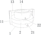
FIG. 1 is a front view of the present invention;
fig. 2 is a schematic structural view of the driving mechanism of the present invention;
FIG. 3 is an exploded view of the present invention;
fig. 4 is a schematic structural diagram of the isolation mechanism of the present invention.
Wherein: 1. a lower membrane shell; 2. coating a membrane shell; 3. forming a groove; 11. a side bracket; 12. a slider; 13. a lifting lever; 14. an endless belt; 15. a circular central column; 21. a material injection pipe; 22. an oil cylinder; 23. an arc-shaped slot; 24. an arc-shaped plate; 25. a rectangular connecting plate; 26. a circular rod; 27. and (6) cutting the ring.
Detailed Description
In order to make the technical means, creation features, achievement objects and functions of the present invention easy to understand, the present invention will be further explained with reference to the following embodiments, however, the following embodiments are only preferred embodiments of the present invention, and not all embodiments are included. Based on the embodiments in the implementation, other embodiments obtained by those skilled in the art without any creative work belong to the protection scope of the present invention. The experimental procedures in the following examples were carried out in a conventional manner unless otherwise specified, and materials, reagents and the like used in the following examples were commercially available unless otherwise specified.
Example (b):
as shown in fig. 1, fig. 2, fig. 3 and fig. 4, a die for a stainless steel flange forging comprises a lower membrane shell 1 and an upper membrane shell 2, wherein the lower membrane shell 1 and the upper membrane shell 2 are movably clamped together, a driving mechanism is arranged between the lower membrane shell 1 and the upper membrane shell 2, and an isolation mechanism is arranged in the lower membrane shell 1 and the upper membrane shell 2;
isolated mechanism includes hydro-cylinder 22, and fixed mounting has rectangle connecting plate 25 on hydro-cylinder 22's the telescopic link, and the lower fixed surface of rectangle connecting plate 25 installs circular rod 26, and fixed mounting has arc 24 below circular rod 26, has seted up arc 23 on lower membrane shell 1 and the last membrane shell 2, and arc 24 activity block is provided with the cutting ring 27 of bolt installation in arc 23 on the arc 24 in the arc 23.
The last fixed surface of lower membrane shell 1 installs annotates material pipe 21, goes up to set up the groove that material pipe 21 was annotated to the block on the membrane shell 2, has all seted up shaping groove 3 in lower membrane shell 1 and the last membrane shell 2, and arc 24 and shaping groove 3 combination form complete circular structure.
Actuating mechanism includes side support 11, and side support 11 fixed mounting is provided with the pneumatic cylinder in on the lateral wall of membrane shell 1 down, and fixed mounting has slider 12 on the telescopic link of this pneumatic cylinder, is provided with lifting rod 13 between the slider 12 and connects, and the lower fixed surface of lifting rod 13 installs girdle 14, and girdle 14 and the last fixed surface of last membrane shell 2 are in the same place, are provided with circular center post 15 down in the membrane shell 1, go up 2 movable clamping of membrane shell on circular center post 15.
The working principle is as follows:
the first step is as follows: add stainless steel solution in membrane shell 1 and last membrane shell 2 downwards through annotating material pipe 21, stainless steel solution is flowing and gets into the shaping groove 3, after solution gets into in the shaping groove 3, fill up in shaping groove 3, through starting cylinder 22, let the telescopic link rebound of cylinder 22, let telescopic link promote the square connecting plate 25 rebound, square connecting plate 25 rebound drives the rebound of round bar 26, thereby drive the rebound of arc 24, in the time of arc 24 rebound, the hole on the notes material pipe 21 can be sheltered from by the lateral wall of arc 24, cutting ring 27 can rebound simultaneously, the hole the same with cutting ring 27 size can not be left on the forming part that forms like this, and after cutting ring 27 laminates on the lateral wall of shaping groove 3, shaping groove 3 just forms complete circular structure, thereby form complete flange, this device is through controlling reciprocating of arc 24, make reciprocating of arc 24 drive reciprocating of cutting ring 27, cut solution, thereby let the circular flange of complete formation 391, thereby improve the shaping effect of flange.
The second step is that: through starting the pneumatic cylinder in the side support 11, let the telescopic link of pneumatic cylinder drive the rebound of slider 12 to drive the rebound of lift bar 13, the rebound of the rebound endless belt 14 of lift bar 13, thereby drive the rebound of last membrane shell 2, let the flange in membrane shell 1 and the last membrane shell 2 expose out, make things convenient for follow-up processing the flange.
The embodiments of the present invention have been described in detail with reference to the accompanying drawings, but the present invention is not limited thereto, and various changes can be made without departing from the gist of the present invention within the scope of knowledge possessed by those skilled in the art.
Claims (6)
1. A stainless steel flange forging die comprises a lower membrane shell (1) and an upper membrane shell (2), wherein the lower membrane shell (1) and the upper membrane shell (2) are movably clamped together, and is characterized in that a driving mechanism is arranged between the lower membrane shell (1) and the upper membrane shell (2), and isolation mechanisms are arranged in the lower membrane shell (1) and the upper membrane shell (2);
isolated mechanism includes hydro-cylinder (22), fixed mounting has rectangle connecting plate (25) on the telescopic link of hydro-cylinder (22), the lower fixed surface of rectangle connecting plate (25) installs round bar (26), fixed mounting has arc (24) below round bar (26), arc (23) have been seted up on lower membrane shell (1) and last membrane shell (2), arc (24) activity block is in arc (23), be provided with cutting ring (27) of bolt installation on arc (24).
2. The die for the stainless steel flange forging piece according to claim 1, wherein a material injection pipe (21) is fixedly installed on the upper surface of the lower membrane shell (1), and a groove for clamping the material injection pipe (21) is formed in the upper membrane shell (2).
3. The die for the stainless steel flange forging piece according to claim 2, wherein forming grooves (3) are formed in the lower membrane shell (1) and the upper membrane shell (2), and the arc-shaped plate (24) and the forming grooves (3) are combined to form a complete circular structure.
4. The die for forging the stainless steel flange as claimed in claim 1, wherein the driving mechanism comprises a side bracket (11), the side bracket (11) is fixedly mounted on the side wall of the lower die shell (1), a hydraulic cylinder is arranged in the side bracket, and a sliding block (12) is fixedly mounted on a telescopic rod of the hydraulic cylinder.
5. A die for forging stainless steel flanges as claimed in claim 4, wherein the sliding blocks (12) are connected by lifting rods (13), the lower surface of each lifting rod (13) is fixedly provided with an annular belt (14), and the annular belt (14) is fixedly arranged with the upper surface of the upper membrane shell (2).
6. The die for the stainless steel flange forging according to claim 5, wherein a circular central column (15) is arranged in the lower membrane shell (1), and the upper membrane shell (2) is movably clamped on the circular central column (15).
Priority Applications (1)
| Application Number | Priority Date | Filing Date | Title |
|---|---|---|---|
| CN202221537159.3U CN217647465U (en) | 2022-06-17 | 2022-06-17 | Stainless steel flange forging mould |
Applications Claiming Priority (1)
| Application Number | Priority Date | Filing Date | Title |
|---|---|---|---|
| CN202221537159.3U CN217647465U (en) | 2022-06-17 | 2022-06-17 | Stainless steel flange forging mould |
Publications (1)
| Publication Number | Publication Date |
|---|---|
| CN217647465U true CN217647465U (en) | 2022-10-25 |
Family
ID=83684409
Family Applications (1)
| Application Number | Title | Priority Date | Filing Date |
|---|---|---|---|
| CN202221537159.3U Active CN217647465U (en) | 2022-06-17 | 2022-06-17 | Stainless steel flange forging mould |
Country Status (1)
| Country | Link |
|---|---|
| CN (1) | CN217647465U (en) |
-
2022
- 2022-06-17 CN CN202221537159.3U patent/CN217647465U/en active Active
Similar Documents
| Publication | Publication Date | Title |
|---|---|---|
| CN210059561U (en) | Forming die for thin-wall metal product | |
| CN214108527U (en) | An environmentally friendly lunch box forming mold | |
| CN214562577U (en) | Injection molding die for automobile valve body component | |
| CN214773669U (en) | Mould that precision is strong | |
| CN209775394U (en) | Mold clamping device | |
| CN211662451U (en) | Mold ejection system | |
| CN211683680U (en) | Quick refrigerated integrated into one piece mould | |
| CN210553225U (en) | Portable demoulding structure of hardware mould | |
| CN216658654U (en) | Mould for preparing straw biomass seedling raising tray | |
| CN216068475U (en) | Automatic cut mouth of a river plastic goods injection mold | |
| CN215703444U (en) | Vertical taper mode locking structure device | |
| CN219464597U (en) | Mould convenient for demoulding | |
| CN113977840A (en) | Mosaic type die structure of silica gel product extruder | |
| CN220445777U (en) | A cutting die for cold-drawn I-channel steel | |
| CN213728873U (en) | Car B post inner panel mold processing | |
| CN206344394U (en) | A kind of mould push piece plate core-pulling device | |
| CN220499779U (en) | Guide plate injection mold | |
| CN216544882U (en) | Lower punching die for producing products with steps | |
| CN217891668U (en) | Robot shell mould of sweeping floor convenient to drawing of patterns | |
| CN219947015U (en) | Laminated high-pressure foaming die | |
| CN223097803U (en) | Stamping die assembly for battery box of new energy automobile | |
| CN212733765U (en) | Die punching device | |
| CN217964372U (en) | Mould with no spring drive structure | |
| CN210059714U (en) | Die for producing cutting box | |
| CN213533677U (en) | Rubber mold |
Legal Events
| Date | Code | Title | Description |
|---|---|---|---|
| GR01 | Patent grant | ||
| GR01 | Patent grant |