CN217594118U - Dust falling device for pneumatic ash removal - Google Patents
Dust falling device for pneumatic ash removal Download PDFInfo
- Publication number
- CN217594118U CN217594118U CN202123094201.7U CN202123094201U CN217594118U CN 217594118 U CN217594118 U CN 217594118U CN 202123094201 U CN202123094201 U CN 202123094201U CN 217594118 U CN217594118 U CN 217594118U
- Authority
- CN
- China
- Prior art keywords
- ash removal
- inner cavity
- collection
- tank body
- pipe
- Prior art date
- Legal status (The legal status is an assumption and is not a legal conclusion. Google has not performed a legal analysis and makes no representation as to the accuracy of the status listed.)
- Expired - Fee Related
Links
- 239000000428 dust Substances 0.000 title claims abstract description 35
- 230000001629 suppression Effects 0.000 claims abstract description 30
- 230000007246 mechanism Effects 0.000 claims abstract description 28
- 239000000463 material Substances 0.000 claims abstract description 14
- 238000000605 extraction Methods 0.000 claims description 5
- 238000007789 sealing Methods 0.000 claims description 4
- 239000000843 powder Substances 0.000 abstract description 35
- 230000009286 beneficial effect Effects 0.000 abstract description 2
- 238000000034 method Methods 0.000 description 3
- 230000009467 reduction Effects 0.000 description 3
- 238000001914 filtration Methods 0.000 description 2
- 239000002245 particle Substances 0.000 description 2
- 239000000126 substance Substances 0.000 description 2
- 238000005299 abrasion Methods 0.000 description 1
- 230000009471 action Effects 0.000 description 1
- 238000001816 cooling Methods 0.000 description 1
- 238000010586 diagram Methods 0.000 description 1
- 238000001035 drying Methods 0.000 description 1
- 230000005611 electricity Effects 0.000 description 1
- 238000010438 heat treatment Methods 0.000 description 1
- 230000002093 peripheral effect Effects 0.000 description 1
- 230000008569 process Effects 0.000 description 1
- 238000005086 pumping Methods 0.000 description 1
- 230000003068 static effect Effects 0.000 description 1
- XLYOFNOQVPJJNP-UHFFFAOYSA-N water Substances O XLYOFNOQVPJJNP-UHFFFAOYSA-N 0.000 description 1
Images



Landscapes
- Filtering Of Dispersed Particles In Gases (AREA)
Abstract
本实用新型公开了一种气力除灰用降尘装置,包括输料机构,包括除灰罐本体,设置于所述除灰罐本体顶部左侧的输料管。本实用新型有益效果为:通过设置除灰罐本体、输料管、第一阀门,使装置具备基本的存储粉状物的功能,通过设置支撑板,以此对空气泵和收集抽屉进行支撑,通过设置空气泵、抽气管、输气管、收集框架、收集抽屉和连接槽,便于将除灰罐本体内腔飘散的粉状物和空气输出至收集抽屉的内腔,解决了现有的气力除灰罐在完成输送作业后,内腔依旧飘散着粉状物,且在罐体的内腔漂浮较长时间,增加了气力除灰装置的使用间隔,影响了气力除灰装置的二次使用,继而降低了气力除灰装置的使用效率的问题。

The utility model discloses a dust suppression device for pneumatic ash removal, which comprises a material conveying mechanism, a ash removal tank body, and a material conveying pipe arranged on the left side of the top of the ash removal tank body. The beneficial effects of the utility model are as follows: by setting the ash removal tank body, the material conveying pipe and the first valve, the device has the basic function of storing powder, and by setting the support plate, the air pump and the collection drawer are supported, By arranging an air pump, an air suction pipe, an air delivery pipe, a collection frame, a collection drawer and a connecting groove, it is convenient to output the powder and air scattered in the inner cavity of the ash removal tank to the inner cavity of the collection drawer, which solves the problem of the existing pneumatic removal. After the ash tank completes the conveying operation, powder still floats in the inner cavity, and floats in the inner cavity of the tank for a long time, which increases the use interval of the pneumatic ash removal device and affects the secondary use of the pneumatic ash removal device. Then the problem of using efficiency of the pneumatic ash removal device is reduced.
Description
技术领域technical field
本实用新型涉及气力除灰技术领域,特别是一种气力除灰用降尘装置。The utility model relates to the technical field of pneumatic ash removal, in particular to a dust suppression device for pneumatic ash removal.
背景技术Background technique
气力输送装置的结构简单,操作方便,可作水平的、垂直的或倾斜方向的输送,在输送过程中还可同时进行物料的加热、冷却、干燥和气流分级等物理操作或某些化学操作,与机械输送相比,此法能量消耗较大,颗粒易受破损,设备也易受磨蚀,含水量多、有粘附性或在高速运动时易产生静电的物料,不宜于进行气力输送。The pneumatic conveying device has a simple structure and is easy to operate. It can be used for horizontal, vertical or inclined conveying. During the conveying process, it can also perform physical operations such as heating, cooling, drying and air classification of materials or some chemical operations. Compared with mechanical conveying, this method consumes more energy, the particles are easily damaged, the equipment is also susceptible to abrasion, materials with high water content, adhesion or static electricity are easily generated during high-speed movement, and are not suitable for pneumatic conveying.
目前的气力除灰装置可以很好完成对粉状物的输送作业,但是现有的气力除灰罐在完成输送作业后,内腔依旧飘散着粉状物,且在罐体的内腔漂浮较长时间,增加了气力除灰装置的使用间隔,影响了气力除灰装置的二次使用,继而降低了气力除灰装置的使用效率。The current pneumatic ash removal device can well complete the conveying operation of powder, but after the existing pneumatic ash removal tank completes the conveying operation, the inner cavity of the existing pneumatic ash removal tank still has powder particles floating in the inner cavity of the tank. For a long time, the use interval of the pneumatic ash removal device is increased, which affects the secondary use of the pneumatic ash removal device, and then reduces the use efficiency of the pneumatic ash removal device.
实用新型内容Utility model content
本部分的目的在于概述本实用新型的实施例的一些方面以及简要介绍一些较佳实施例。在本部分以及本申请的说明书摘要和实用新型名称中可能会做些简化或省略以避免使本部分、说明书摘要和实用新型名称的目的模糊,而这种简化或省略不能用于限制本实用新型的范围。The purpose of this section is to outline some aspects of embodiments of the invention and to briefly introduce some preferred embodiments. Some simplifications or omissions may be made in this part and the abstract of the specification and the title of the utility model of this application to avoid obscuring the purpose of this part, the abstract of the specification and the title of the utility model, and such simplification or omission cannot be used to limit the utility model range.
鉴于上述和/或现有的气力除灰用降尘装置中存在的问题,提出了本实用新型。In view of the above-mentioned and/or existing problems in the dust suppression device for pneumatic ash removal, the present utility model is proposed.
因此,本实用新型所要解决的问题在于目前的气力除灰装置可以很好完成对粉状物的输送作业,但是现有的气力除灰罐在完成输送作业后,内腔依旧飘散着粉状物,且在罐体的内腔漂浮较长时间,增加了气力除灰装置的使用间隔,影响了气力除灰装置的二次使用,继而降低了气力除灰装置的使用效率。Therefore, the problem to be solved by the present utility model is that the current pneumatic ash removal device can well complete the conveying operation of the powder, but after the existing pneumatic ash removal tank completes the conveying operation, the inner cavity of the existing pneumatic ash removal tank still has powdery substances floating in it. , and floats in the inner cavity of the tank for a long time, which increases the use interval of the pneumatic ash removal device, affects the secondary use of the pneumatic ash removal device, and then reduces the use efficiency of the pneumatic ash removal device.
为解决上述技术问题,本实用新型提供如下技术方案:一种气力除灰用降尘装置,其包括,输料机构,包括除灰罐本体,设置于所述除灰罐本体顶部左侧的输料管,以及设置于所述输料管表面的第一阀门;In order to solve the above technical problems, the present utility model provides the following technical solutions: a dust suppression device for pneumatic ash removal, which includes a material conveying mechanism, including an ash removal tank body, and a material conveying device disposed on the left side of the top of the ash removal tank body. a pipe, and a first valve arranged on the surface of the feeding pipe;
收集机构,包括支撑板,设置于所述支撑板顶部前端右侧的空气泵,设置于所述空气泵进气端的抽气管,设置于所述空气泵出气端的输气管,设置于所述支撑板顶部前端左侧的收集框架,设置于所述收集框架内腔右侧的收集抽屉,设置于所述收集框架右侧与所述收集抽屉右侧的连接槽,以及设置于所述收集抽屉左侧的第一过滤网。The collection mechanism includes a support plate, an air pump arranged on the right side of the front end of the top of the support plate, an air suction pipe arranged at the air inlet end of the air pump, an air delivery pipe arranged at the air outlet end of the air pump, and an air pump arranged at the support plate The collection frame on the left side of the front end of the top, the collection drawer on the right side of the inner cavity of the collection frame, the connecting groove on the right side of the collection frame and the right side of the collection drawer, and the left side of the collection drawer the first filter.
作为本实用新型所述气力除灰用降尘装置的一种优选方案,其中:所述抽气管远离所述空气泵的一端与所述除灰罐本体的内腔连通,所述输气管远离所述空气泵的一端与位于所述收集框架右侧所述连接槽的内腔连通。As a preferred solution of the dust suppression device for pneumatic ash removal of the present invention, wherein: the end of the air extraction pipe away from the air pump is communicated with the inner cavity of the ash removal tank body, and the air delivery pipe is far away from the One end of the air pump communicates with the inner cavity of the connecting groove on the right side of the collecting frame.
作为本实用新型所述气力除灰用降尘装置的一种优选方案,其中:所述输料机构还包括支架,设置于所述除灰罐本体表面的四周,以及设置于所述支架与所述支撑板底部四周的支撑柱。As a preferred solution of the dust suppression device for pneumatic ash removal of the present invention, wherein: the conveying mechanism further includes a bracket, which is arranged around the surface of the ash removal tank body, and is arranged between the bracket and the Support columns around the bottom of the support plate.
作为本实用新型所述气力除灰用降尘装置的一种优选方案,其中:所述输料机构还包括进气管、设置于所述除灰罐本体顶部的右侧,以及设置于所述进气管表面第二阀门。As a preferred solution of the dust suppression device for pneumatic ash removal of the present invention, wherein: the conveying mechanism further comprises an air inlet pipe, which is arranged on the right side of the top of the ash removal tank body, and is arranged on the air inlet pipe. Surface second valve.
作为本实用新型所述气力除灰用降尘装置的一种优选方案,其中:所述输料机构还包括出料管、设置于所述除灰罐本体的底部,以及设置于所述出料管表面的第三阀门。As a preferred solution of the dust suppression device for pneumatic ash removal of the present invention, wherein: the conveying mechanism further comprises a discharge pipe, which is arranged at the bottom of the ash removal tank body, and is arranged on the discharge pipe The third valve on the surface.
作为本实用新型所述气力除灰用降尘装置的一种优选方案,其中:所述收集机构还包括滑槽、设置于所述收集框架内腔底部的中心处与右侧,以及设置于所述收集抽屉底部两侧的滑块。As a preferred solution of the dust suppression device for pneumatic ash removal of the present invention, wherein: the collection mechanism further includes a chute, arranged at the center and the right side of the bottom of the inner cavity of the collection frame, and arranged at the bottom of the collection frame. Gather the sliders on each side of the bottom of the drawer.
作为本实用新型所述气力除灰用降尘装置的一种优选方案,其中:所述支撑板与所述支架的前端固定连接,所述滑块的底部延伸至所述滑槽内腔的底部,且与所述滑槽的内腔活动连接。As a preferred solution of the dust suppression device for pneumatic ash removal of the present invention, wherein: the support plate is fixedly connected with the front end of the bracket, the bottom of the slider extends to the bottom of the inner cavity of the chute, And it is movably connected with the inner cavity of the chute.
作为本实用新型所述气力除灰用降尘装置的一种优选方案,其中:所述收集机构还包括盖板、设置于所述收集抽屉的顶部,以及设置于所述收集框架左侧的第二过滤网。As a preferred solution of the dust suppression device for pneumatic ash removal of the present invention, wherein: the collection mechanism further comprises a cover plate, a top plate arranged on the top of the collection drawer, and a second cover arranged on the left side of the collection frame. Filter.
作为本实用新型所述气力除灰用降尘装置的一种优选方案,其中:所述收集机构还包括过滤海绵、设置于所述收集抽屉内腔底部的左侧。As a preferred solution of the dust suppression device for pneumatic ash removal of the present invention, wherein: the collection mechanism further includes a filter sponge, which is arranged on the left side of the bottom of the inner cavity of the collection drawer.
作为本实用新型所述气力除灰用降尘装置的一种优选方案,其中:所述收集机构还包括密封条、设置于所述收集抽屉右侧的表面,以及设置于所述抽气管表面的第四阀门。As a preferred solution of the dust suppression device for pneumatic ash removal according to the present invention, wherein: the collection mechanism further comprises a sealing strip, a surface arranged on the right side of the collection drawer, and a second surface arranged on the surface of the air extraction pipe. Four valves.
本实用新型有益效果为:通过设置除灰罐本体、输料管、第一阀门,使装置具备基本的存储粉状物的功能,通过设置支撑板,以此对空气泵和收集抽屉进行支撑,通过设置空气泵、抽气管、输气管、收集框架、收集抽屉和连接槽,便于将除灰罐本体内腔飘散的粉状物和空气输出至收集抽屉的内腔,并经过第一过滤网的拦截将粉状物拦截在收集抽屉的内腔,从而将除灰罐本体内腔的粉状物抽送至收集抽屉的内腔,以此完成对除灰罐本体内腔的降尘作业,快速将除灰罐本体内腔飘散的粉状物进行收集,降低气力除灰装置的使用间隔时间,从而增加了装置的使用效率。The beneficial effects of the utility model are as follows: by arranging the ash removal tank body, the material conveying pipe and the first valve, the device has the basic function of storing powders; By arranging an air pump, an air suction pipe, an air delivery pipe, a collection frame, a collection drawer and a connecting groove, it is convenient to output the powder and air scattered in the inner cavity of the ash removal tank to the inner cavity of the collection drawer, and pass through the first filter screen. The interception intercepts the powder in the inner cavity of the collection drawer, so that the powder in the inner cavity of the ash removal tank is pumped to the inner cavity of the collection drawer, so as to complete the dust reduction operation on the inner cavity of the ash removal tank, and quickly remove the dust. The powder scattered in the inner cavity of the ash tank body is collected to reduce the use interval of the pneumatic ash removal device, thereby increasing the use efficiency of the device.
附图说明Description of drawings
为了更清楚地说明本实用新型实施例的技术方案,下面将对实施例描述中所需要使用的附图作简单地介绍,显而易见地,下面描述中的附图仅仅是本实用新型的一些实施例,对于本领域普通技术人员来讲,在不付出创造性劳动性的前提下,还可以根据这些附图获得其它的附图。其中:In order to illustrate the technical solutions of the embodiments of the present invention more clearly, the following briefly introduces the accompanying drawings used in the description of the embodiments. Obviously, the drawings in the following description are only some embodiments of the present invention. , for those of ordinary skill in the art, other drawings can also be obtained from these drawings without creative labor. in:
图1为气力除灰用降尘装置的结构图。Fig. 1 is a structural diagram of a dust suppression device for pneumatic ash removal.
图2为气力除灰用降尘装置的收集框架剖视结构图。Fig. 2 is a cross-sectional structural view of the collection frame of the dust suppression device for pneumatic ash removal.
图3为气力除灰用降尘装置的收集抽屉主视立体结构图。Fig. 3 is a front perspective structural view of the collection drawer of the dust suppression device for pneumatic ash removal.
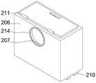
图4为气力除灰用降尘装置的收集抽屉后视立体结构图。FIG. 4 is a rear perspective structural view of the collection drawer of the dust suppression device for pneumatic ash removal.
图5为气力除灰用降尘装置的空气泵立体结构图。FIG. 5 is a three-dimensional structural view of an air pump of a dust suppression device for pneumatic ash removal.
具体实施方式Detailed ways
为使本实用新型的上述目的、特征和优点能够更加明显易懂,下面结合说明书附图对本实用新型的具体实施方式做详细的说明。In order to make the above objects, features and advantages of the present invention more clearly understood, the specific embodiments of the present invention will be described in detail below with reference to the accompanying drawings.
在下面的描述中阐述了很多具体细节以便于充分理解本实用新型,但是本实用新型还可以采用其他不同于在此描述的其它方式来实施,本领域技术人员可以在不违背本实用新型内涵的情况下做类似推广,因此本实用新型不受下面公开的具体实施例的限制。In the following description, many specific details are set forth in order to fully understand the present utility model, but the present utility model can also be implemented in other ways different from those described herein, and those skilled in the art can do so without departing from the connotation of the present utility model. Therefore, the present invention is not limited by the specific embodiments disclosed below.
其次,此处所称的“一个实施例”或“实施例”是指可包含于本实用新型至少一个实现方式中的特定特征、结构或特性。在本说明书中不同地方出现的“在一个实施例中”并非均指同一个实施例,也不是单独的或选择性的与其他实施例互相排斥的实施例。Second, reference herein to "one embodiment" or "an embodiment" refers to a particular feature, structure, or characteristic that may be included in at least one implementation of the present invention. The appearances of "in one embodiment" in various places in this specification are not all referring to the same embodiment, nor are they separate or selectively mutually exclusive from other embodiments.
实施例1Example 1
参照图1~4,为本实用新型第一个实施例,该实施例提供了一种气力除灰用降尘装置,气力除灰用降尘装置包括输料机构100,包括除灰罐本体101,设置于除灰罐本体101顶部左侧的输料管102,以及设置于输料管102表面的第一阀门103。1 to 4, the first embodiment of the present utility model provides a dust suppression device for pneumatic ash removal. The dust suppression device for pneumatic ash removal includes a
收集机构200,包括支撑板201,设置于支撑板201顶部前端右侧的空气泵202,设置于空气泵202进气端的抽气管203,设置于空气泵202出气端的输气管204,设置于支撑板201顶部前端左侧的收集框架205,设置于收集框架205内腔右侧的收集抽屉206,设置于收集框架205右侧与收集抽屉206右侧的连接槽207,以及设置于收集抽屉206左侧的第一过滤网208,通过设置除灰罐本体101、输料管102、第一阀门103,使装置具备基本的存储粉状物的功能,通过设置支撑板201,以此对空气泵202和收集抽屉206进行支撑,通过设置空气泵202、抽气管203、输气管204、收集框架205、收集抽屉206和连接槽207,便于将除灰罐本体101内腔飘散的粉状物和空气输出至收集抽屉206的内腔,并经过第一过滤网208的拦截将粉状物拦截在收集抽屉206的内腔,从而将除灰罐本体101内腔的粉状物抽送至收集抽屉206的内腔,以此完成对除灰罐本体101内腔的降尘作业,快速将除灰罐本体101内腔飘散的粉状物进行收集,降低气力除灰装置的使用间隔时间,从而增加了装置的使用效率。The
具体的,抽气管203远离空气泵202的一端与除灰罐本体101的内腔连通,输气管204远离空气泵202的一端与位于收集框架205右侧连接槽207的内腔连通。Specifically, the end of the
具体的,输料机构100还包括支架104,设置于除灰罐本体101表面的四周,以及设置于支架104与支撑板201底部四周的支撑柱105,通过设置支架104和支撑柱105,以此完成的对除灰罐本体101与支撑板201的支撑。Specifically, the
优选的,输料机构100还包括进气管106、设置于除灰罐本体101顶部的右侧,以及设置于进气管106表面第二阀门107,通过设置进气管106和第二阀门107,配合除灰罐本体101使除灰罐本体101可以在外部输气装置的作用下朝除灰罐本体101的内腔进行输气作业。Preferably, the
较佳的,输料机构100还包括出料管108、设置于除灰罐本体101的底部,以及设置于出料管108表面的第三阀门109,通过设置出料管108和第三阀门109,配合输料管102和进气管106将除灰罐本体101内腔的粉状物传输至外部收集装置的内腔。Preferably, the
在使用时,通过外部输料装置配合输料管102、第一阀门103与除灰罐本体101将待传输的粉状物输出至除灰罐本体101的内腔,接着通过外部输气装置配合进气管106、第二阀门107、出料管108和第三阀门109,将除灰罐本体101内腔的粉状物输出至外部的收集装置中。When in use, the powder to be transported is output to the inner cavity of the ash
实施例2Example 2
参照图2~4,为本实用新型第二个实施例,本实施例基于上一个实施例:Referring to Figures 2 to 4, the second embodiment of the present invention is based on the previous embodiment:
优选的,收集机构200还包括滑槽209、设置于收集框架205内腔底部的中心处与右侧,以及设置于收集抽屉206底部两侧的滑块210。Preferably, the
较佳的,支撑板201与支架104的前端固定连接,滑块210的底部延伸至滑槽209内腔的底部,且与滑槽209的内腔活动连接,通过设置滑槽209和滑块210,便于抽拉收集抽屉206,以此便于对收集抽屉206内腔的粉状物进行收集处理。Preferably, the
在使用时,若需要对收集抽屉206内腔的粉状物进行收集,使用者可以拉动收集抽屉206,收集抽屉206带动滑块210沿着滑槽209的内腔位移,并将收集抽屉206内腔的粉状物收集在收集仓中,以此完成对粉状物的收集。During use, if the powder in the inner cavity of the
实施例3Example 3
参照图1~4,为本实用新型第三个实施例,该实施例基于前两个实施例:1 to 4, it is the third embodiment of the present invention, which is based on the first two embodiments:
具体的,收集机构200还包括盖板211、设置于收集抽屉206的顶部,以及设置于收集框架205左侧的第二过滤网212,通过设置盖板211和第二过滤网212,增加收集框架205对粉状物的过滤能力。Specifically, the
优选的,收集机构200还包括过滤海绵213、设置于收集抽屉206内腔底部的左侧,通过设置过滤海绵213,进一步增加收集框架205对粉状物的过滤拦截。Preferably, the
较佳的,收集机构200还包括密封条214、设置于收集抽屉206右侧的表面,以及设置于抽气管203表面的第四阀门215,通过设置密封条214和第四阀门215,增加两个连接槽207之间的密封性,同时便于对抽气管203的开启与闭合进行控制。Preferably, the
在使用时,首先通过外部输料装置配合输料管102、第一阀门103与除灰罐本体101将待传输的粉状物输出至除灰罐本体101的内腔,接着通过外部输气装置配合进气管106、第二阀门107、出料管108和第三阀门109,将除灰罐本体101内腔的粉状物输出至外部的收集装置中,此时除灰罐本体101的内腔残留的粉状物在除灰罐本体101的内腔飘散,使用者打开第四阀门215,并通过外设控制器启动空气泵202,空气泵202配合抽气管203、输气管204、连接槽207将除灰罐本体101内腔中含有粉状物的空气输出至收集抽屉206的内腔,并经过第一过滤网208的过滤,第一过滤网208将粉状物拦截在收集抽屉206的内腔,接着空气经过过滤海绵213与第二过滤网212的过滤拦截后输出至外部环境中,以此完成对除灰罐本体101内腔飘散粉状物的收集作业,并完成对除灰罐本体101内腔的降尘作业,若需要对收集抽屉206内腔的粉状物进行收集,使用者可以拉动收集抽屉206,收集抽屉206带动滑块210沿着滑槽209的内腔位移,并将收集抽屉206内腔的粉状物收集在收集仓中,以此完成对粉状物的收集。When in use, the powder to be transported is firstly output to the inner cavity of the ash
应说明的是,以上实施例仅用以说明本实用新型的技术方案而非限制,尽管参照较佳实施例对本实用新型进行了详细说明,本领域的普通技术人员应当理解,可以对本实用新型的技术方案进行修改或者等同替换,而不脱离本实用新型技术方案的精神和范围,其均应涵盖在本实用新型的权利要求范围当中。It should be noted that the above embodiments are only used to illustrate the technical solutions of the present invention and not to limit them. Although the present invention has been described in detail with reference to the preferred embodiments, those of ordinary skill in the art should The technical solutions can be modified or equivalently replaced without departing from the spirit and scope of the technical solutions of the present invention, and they should all be included in the scope of the claims of the present invention.
Claims (10)
Priority Applications (1)
| Application Number | Priority Date | Filing Date | Title |
|---|---|---|---|
| CN202123094201.7U CN217594118U (en) | 2021-12-10 | 2021-12-10 | Dust falling device for pneumatic ash removal |
Applications Claiming Priority (1)
| Application Number | Priority Date | Filing Date | Title |
|---|---|---|---|
| CN202123094201.7U CN217594118U (en) | 2021-12-10 | 2021-12-10 | Dust falling device for pneumatic ash removal |
Publications (1)
| Publication Number | Publication Date |
|---|---|
| CN217594118U true CN217594118U (en) | 2022-10-18 |
Family
ID=83562247
Family Applications (1)
| Application Number | Title | Priority Date | Filing Date |
|---|---|---|---|
| CN202123094201.7U Expired - Fee Related CN217594118U (en) | 2021-12-10 | 2021-12-10 | Dust falling device for pneumatic ash removal |
Country Status (1)
| Country | Link |
|---|---|
| CN (1) | CN217594118U (en) |
-
2021
- 2021-12-10 CN CN202123094201.7U patent/CN217594118U/en not_active Expired - Fee Related
Similar Documents
| Publication | Publication Date | Title |
|---|---|---|
| CN102217914B (en) | Robot system | |
| CN103263816A (en) | Air box-bag type dust collector integrated with high efficiency cyclone dust collection | |
| CN210585322U (en) | Dustless crushing work station | |
| CN108176148A (en) | A kind of circulation type powder filter device and filter method based on Bernoulli effect | |
| CN219149540U (en) | Furniture processing dust filter equipment | |
| CN216613214U (en) | An electrical automatic coal conveying channel | |
| CN209143203U (en) | A kind of multi-function metal powder collecting box | |
| CN211755836U (en) | Crusher dust collector and crusher | |
| CN203075774U (en) | Flag-bag dust collector | |
| CN209238159U (en) | With the negative pressure system on waste stone exhaust system on air dry sand Recognition Applied in Coal Preparation System | |
| CN107814223A (en) | A kind of graphite dust processing recovery method based on double dust collection unit | |
| CN209178521U (en) | Natural feather high-efficient deferrization exclusion device | |
| CN208326299U (en) | A kind of Wet-dry recover of automatic drain | |
| CN216335251U (en) | Vacuum feeding machine | |
| CN217312496U (en) | High-voltage pulse dust remover for head and tail of belt conveyor | |
| CN208292903U (en) | One kind being convenient for recombination human basic fibroblast growth factor capsule raw material collection device | |
| CN208097668U (en) | Separate room off-line dust cleaning assembled dust collector | |
| CN210763179U (en) | A new type of material conveying device | |
| CN217526750U (en) | A kind of ash discharge device for electric dust removal and energy saving | |
| CN217043347U (en) | Road surface shot blasting machine filter equipment | |
| CN221752753U (en) | Three-stage dust removal device | |
| CN205073793U (en) | Air filter | |
| CN211303710U (en) | A kind of water-soluble fertilizer granulation conveying mechanism | |
| CN209405956U (en) | It is a kind of for separating the secondary ash collector of soft magnetic powder | |
| CN223478178U (en) | Feeding dust removal mechanism and injection molding machine |
Legal Events
| Date | Code | Title | Description |
|---|---|---|---|
| GR01 | Patent grant | ||
| GR01 | Patent grant | ||
| CF01 | Termination of patent right due to non-payment of annual fee |
Granted publication date: 20221018 |
|
| CF01 | Termination of patent right due to non-payment of annual fee |