CN217559668U - Double-end wall lamp - Google Patents
Double-end wall lamp Download PDFInfo
- Publication number
- CN217559668U CN217559668U CN202221720722.0U CN202221720722U CN217559668U CN 217559668 U CN217559668 U CN 217559668U CN 202221720722 U CN202221720722 U CN 202221720722U CN 217559668 U CN217559668 U CN 217559668U
- Authority
- CN
- China
- Prior art keywords
- lamp
- end cover
- wall
- installation cavity
- double
- Prior art date
- Legal status (The legal status is an assumption and is not a legal conclusion. Google has not performed a legal analysis and makes no representation as to the accuracy of the status listed.)
- Active
Links
Images


Landscapes
- Arrangement Of Elements, Cooling, Sealing, Or The Like Of Lighting Devices (AREA)
Abstract
The utility model discloses a double-end wall lamp, which comprises a lamp shell, a light-emitting component and a sealing component, wherein an installation cavity is arranged in the lamp shell, the light-emitting component and the sealing component are arranged at the two ends of the installation cavity, and the light-emitting component is positioned in the installation cavity; each sealing assembly comprises a sealing ring, a transparent pressing plate and an end cover, the sealing ring is clamped with the outer wall of the installation cavity, one side, away from the installation cavity, of the sealing ring is provided with the end cover, the end cover is fixedly connected with the lamp shell, and the transparent pressing plate is arranged between the end cover and the sealing ring. Compared with the prior art the utility model discloses simple structure, simple to operate use the physical structure to seal, have avoided adopting the encapsulating to seal the cost of bringing too high, the not good condition of sealed effect.
Description
Technical Field
The utility model belongs to the technical field of lighting apparatus, specifically belong to a double-end wall lamp.
Background
The wall lamp is an auxiliary lighting decorative lamp installed on the wall, and is generally provided with a milky glass lampshade. The wall lamps are mostly arranged on balconies, stairs, corridor passageways and bedrooms and are suitable for being used as changming lamps, the wall lamps are various in types, and the color-changing wall lamps are mostly used in festivals and festivals; most bedside wall lamps are arranged at the left upper part of the bedside, the lamp holder can rotate universally, light beams are concentrated, and reading is facilitated; the front wall mirror lamp is often used near a bathroom mirror for decoration.
Because the influence of weather can appear the drop of water on the wall, also contains steam in the air, and the drop of water on the wall can enter into the wall lamp along the wall, leads to the inside of wall lamp to take place the short circuit, and the influence is used, and the mode of adopting the encapsulating usually of current wall lamp is waterproof, and this kind of waterproof means cost is higher, and technology is complicated, and its leakproofness descends gradually as time goes on, consequently is necessary to improve current wall lamp structure.
SUMMERY OF THE UTILITY MODEL
In view of this, the utility model aims at overcoming among the prior art not enough, provide a double-end wall lamp. The application provides the following technical scheme:
a double-end wall lamp comprises a lamp shell, a light-emitting component and a sealing component, wherein an installation cavity is arranged in the lamp shell, the light-emitting component and the sealing component are arranged at two ends of the installation cavity, and the light-emitting component is located in the installation cavity;
each sealing assembly comprises a sealing ring, a transparent pressing plate and an end cover, the sealing ring is clamped with the outer wall of the installation cavity, one side, far away from the installation cavity, of the sealing ring is provided with the end cover, the end cover is fixedly connected with the lamp housing, and the transparent pressing plate is arranged between the end cover and the sealing ring.
In one possible embodiment, a heat sink is disposed in the mounting cavity, and the light emitting assembly is disposed at both ends of the heat sink.
In one possible embodiment, the transparent platen is tempered glass.
In one possible embodiment, the sealing ring is a silicone ring.
In one possible embodiment, each light-emitting assembly comprises a circuit board, an LED lamp and a lens, the circuit board is arranged inside the mounting chamber, the LED lamp is arranged on one side of the circuit board close to the corresponding transparent pressing plate, and the lens is arranged between the LED lamp and the transparent pressing plate.
In one possible embodiment, a lamp fixture is provided at one side of the lamp housing, said lamp fixture being adapted to be connected to a wall.
In a possible embodiment, a limiting notch is formed in the middle of the end cover, a limiting wall is formed around the limiting notch and used for pressing the transparent pressing plate, and a flow guide channel is further formed in the end cover and extends from the edge of the end cover to the limiting notch.
In a possible embodiment, the diversion channel is obliquely arranged, the height of one end, close to the limit notch, of the diversion channel is higher than that of one end, close to the edge of the end cover, of the diversion channel, and the horizontal plane of the end, close to the limit notch, of the diversion channel is flush with the horizontal plane, used for pressing the transparent pressing plate, of the limit wall.
To sum up, owing to adopted above-mentioned technical scheme, the beneficial effects of the utility model are that:
the utility model discloses improve current wall lamp, designed a double-end wall lamp, all set up light-emitting component at the both ends of lamp body installation cavity to the both ends of lamp body all are provided with seal assembly, utilize end cover and transparent clamp plate to compress tightly the sealing washer and play waterproof effect, guarantee sealed effect, compare with prior art the utility model discloses simple structure, simple to operate use the physical structure to seal, have avoided adopting the sealed condition of bringing of encapsulating cost too high, sealed effect is not good.
In order to make the aforementioned objects, features and advantages of the present application more apparent and understandable, preferred embodiments are described below in detail with reference to the accompanying drawings.
Drawings
In order to more clearly illustrate the technical solutions of the embodiments of the present application, the drawings that are required to be used in the embodiments will be briefly described below, it should be understood that the following drawings only illustrate some embodiments of the present invention, and therefore should not be considered as limiting the scope, and for those skilled in the art, other related drawings can be obtained according to the drawings without inventive efforts.
Fig. 1 is a schematic diagram of the explosion structure of the present invention.
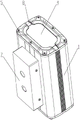
Fig. 2 is a schematic view of the assembly structure of the present invention.
Fig. 3 is a schematic view of the internal section of the present invention.
Reference numerals: 1-a lamp housing; 2-installing a chamber; 3-sealing ring; 4-a transparent platen; 5-end cover; 6-a light emitting component; 7-lamp fixtures; 8-a flow guide channel; 9-radiator.
Detailed Description
Reference will now be made in detail to embodiments of the present application, examples of which are illustrated in the accompanying drawings, wherein like or similar reference numerals refer to the same or similar elements or elements having the same or similar function throughout. The embodiments described below with reference to the accompanying drawings are illustrative and are only for the purpose of explaining the present application and are not to be construed as limiting the present application.
In the description of the present application, it is to be understood that the terms "center," "longitudinal," "lateral," "length," "width," "thickness," "upper," "lower," "front," "rear," "left," "right," "vertical," "horizontal," "top," "bottom," "inner," "outer," "clockwise," "counterclockwise," "axial," "radial," "circumferential," and the like are used in the orientations and positional relationships indicated in the drawings for convenience in describing the present application and for simplicity in description, and are not intended to indicate or imply that the referenced devices or elements must have a particular orientation, be constructed and operated in a particular orientation, and are therefore not to be considered limiting of the present application.
Furthermore, the terms "first", "second" and "first" are used for descriptive purposes only and are not to be construed as indicating or implying relative importance or implicitly indicating the number of technical features indicated. Thus, a feature defined as "first" or "second" may explicitly or implicitly include one or more of that feature. In the description of the present application, "a plurality" means two or more unless specifically limited otherwise.
In this application, unless expressly stated or limited otherwise, the terms "mounted," "connected," "secured," and the like are to be construed broadly and encompass, for example, both fixed and removable connections or integral parts thereof; can be mechanically or electrically connected; either directly or indirectly through intervening media, either internally or in any other relationship. The specific meaning of the above terms in the present application can be understood by those of ordinary skill in the art as appropriate.
In this application, unless expressly stated or limited otherwise, the first feature "on" or "under" the second feature may be directly contacting the first and second features or indirectly contacting the first and second features through intervening media. Also, a first feature "on," "above," and "over" a second feature may be directly on or obliquely above the second feature, or simply mean that the first feature is at a higher level than the second feature. A first feature "under," "beneath," and "under" a second feature may be directly under or obliquely under the second feature, or may simply mean that the first feature is at a lesser elevation than the second feature.
The double-end wall lamp provided by the embodiment comprises a lamp shell 1, a light-emitting component and a sealing component, wherein an installation cavity 2 is arranged in the lamp shell 1, the light-emitting component and the sealing component are arranged at two ends of the installation cavity 2, and the light-emitting component 6 is located in the installation cavity 2; each sealing assembly comprises a sealing ring 3, a transparent pressing plate 4 and an end cover 5, the sealing ring 3 is connected with the outer wall of the installation cavity 2 in a clamped mode, one side, far away from the installation cavity 2, of the sealing ring 3 is provided with the end cover 5, the end cover 5 is fixedly connected with the lamp housing 1, and the transparent pressing plate 4 is arranged between the end cover 5 and the sealing ring 3.
A radiator 9 is arranged in the mounting cavity 2, and the light-emitting component 6 is arranged at both ends of the radiator 9.
It should be noted that improve current wall lamp in above-mentioned embodiment one, design a wall lamp that both ends are luminous and waterproof performance is superior, it is concrete, as shown in fig. 1, fig. 1 is the utility model discloses an explosion schematic diagram, from left to right do in proper order, end cover 5, transparent clamp plate 4, sealing washer 3, light-emitting component 6, lamp body 1 and radiator 9, wherein lamp body 1 is the rectangle box structure, both ends opening, the middle part has installation cavity 2, the assembly the utility model discloses the time, fix light-emitting component 6 through the bolt at the both ends of radiator 9 in advance, then pack into installation cavity 2 with radiator 9 together with light-emitting component 6, after the assembly well install sealing washer 3 at the both ends of installation cavity 2, have the joint groove on sealing washer 3, can with the lateral wall cooperation of installation cavity 2, ensure that sealing washer 3 assembles the back, place transparent clamp plate 4 on sealing washer 3, again place end cover 5 on transparent clamp plate 4, lock end cover 5 and lamp body 1 and extrude sealing washer 3 through end cover 5 with the bolt, both ends play fine waterproof effect through extrusion sealing washer 3.
The LED lamp is further improved on the basis of the first embodiment, namely in a second possible embodiment, the transparent pressing plate 4 is made of toughened glass, the sealing ring 3 is a silica gel ring, each light-emitting assembly 6 comprises a circuit board, an LED lamp and a lens, the circuit board is arranged inside the installation cavity 2, the LED lamp is arranged on one side, close to the corresponding transparent pressing plate 4, of the circuit board, the lens is arranged between the LED lamp and the transparent pressing plate 4, a lamp fixing piece 7 is arranged on one side of the lamp housing 1, and the lamp fixing piece 7 is used for being connected with a wall.
In the second embodiment, the light emitting assembly 6 comprises a circuit board, an LED lamp and a lens, the circuit board is fixed at two ends of the heat sink 9, the LED lamp and the lens are assembled, the transparent pressing plate 4 is preferably made of toughened glass, the transparent pressing plate plays a role of pressing the sealing ring 3 and transmits a light source, and the sealing ring 3 is preferably made of a silica gel ring; as shown in fig. 2, a lamp fixing member 7 is disposed on one side of the lamp housing 1, the lamp fixing member 7 is a box structure, a side surface of the box structure is fixed to a wall, and a conductive wire is disposed inside the box structure.
The structure is further improved on the basis of the first embodiment, namely in a third possible embodiment, a limiting notch is formed in the middle of the end cover 5, a limiting wall is formed around the limiting notch and used for pressing the transparent pressing plate 4, a flow guide channel 8 is further arranged on the end cover 5, the flow guide channel 8 extends to the limiting notch from the edge of the end cover 5, the flow guide channel 8 is obliquely arranged, one end, close to the limiting notch, of the flow guide channel 8 is higher than one end, close to the edge of the end cover 5, of the flow guide channel 8, and the end horizontal plane, close to the limiting notch, of the flow guide channel 8 and the horizontal plane, close to the limiting notch, of the transparent pressing plate 4 and used for pressing the limiting wall are flush.
When the utility model discloses install on the wall, the condition of ponding and laying dust may appear at the top of wall lamp, in order to solve this problem, as shown in fig. 3, this embodiment is three to set up spacing breach and form spacing wall on end cover 5, the area of the spacing breach of the area size of transparent clamp plate 4, when end cover 5 is placed on transparent clamp plate 4, spacing wall can compress tightly transparent clamp plate 4, set up water conservancy diversion passageway 8 around end cover 5, set up four water conservancy diversion passageways 8 in this embodiment, evenly arrange on end cover 5, water conservancy diversion passageway 8 extends to spacing breach always from end cover 5 outward flange department, pile up like this at end cover 5 center department promptly spacing breach department's rainwater and dust, can leave end cover 5 along water conservancy diversion passageway 8, rainwater and dust have been avoided piling up on end cover 5, in this embodiment, in order to guarantee water conservancy diversion passageway 8's water conservancy diversion effect, water conservancy diversion passageway 8 can slope sets up, the one end that is higher than the one end that is close to spacing breach, and the horizontal plane that is close to the one end of spacing breach and the horizontal plane of transparent clamp plate 4 flushes of one end.
In the description herein, reference to the description of the term "one embodiment," "some embodiments," "an example," "a specific example," or "some examples," etc., means that a particular feature, structure, material, or characteristic described in connection with the embodiment or example is included in at least one embodiment or example of the application. In this specification, the schematic representations of the terms used above are not necessarily intended to refer to the same embodiment or example. Furthermore, the particular features, structures, materials, or characteristics described may be combined in any suitable manner in any one or more embodiments or examples. Moreover, various embodiments or examples and features of various embodiments or examples described in this specification can be combined and combined by one skilled in the art without being mutually inconsistent.
Although embodiments of the present application have been shown and described above, it is understood that the above embodiments are exemplary and should not be construed as limiting the present application, and that variations, modifications, substitutions and alterations may be made to the above embodiments by those of ordinary skill in the art within the scope of the present application.
Claims (8)
1. The utility model provides a double-end wall lamp which characterized in that: the LED lamp comprises a lamp shell (1), a light-emitting component and a sealing component, wherein an installation cavity (2) is arranged in the lamp shell (1), the light-emitting component and the sealing component are arranged at two ends of the installation cavity (2), and the light-emitting component (6) is positioned in the installation cavity (2);
each sealing assembly comprises a sealing ring (3), a transparent pressing plate (4) and an end cover (5), the sealing ring (3) is connected with the outer wall of the installation cavity (2) in a clamping mode, one side, far away from the installation cavity (2), of the sealing ring (3) is provided with the end cover (5), the end cover (5) is fixedly connected with the lamp housing (1), and the transparent pressing plate (4) is arranged between the end cover (5) and the sealing ring (3).
2. A double-ended wall lamp as claimed in claim 1, wherein: a radiator (9) is arranged in the mounting cavity (2), and the two ends of the radiator (9) are provided with the light-emitting assemblies (6).
3. A double-ended wall lamp as claimed in claim 1, wherein: the transparent pressing plate (4) is made of toughened glass.
4. A double-ended wall lamp as claimed in claim 1, wherein: the sealing ring (3) is a silica gel ring.
5. A double-ended wall lamp as claimed in claim 1, wherein: each light-emitting component (6) comprises a circuit board, an LED lamp and a lens, the circuit board is arranged inside the installation cavity (2), the LED lamp is arranged on one side, close to the corresponding transparent pressing plate (4), of the circuit board, and the lens is arranged between the LED lamp and the transparent pressing plate (4).
6. A double-ended wall lamp as claimed in claim 1, wherein: and a lamp fixing piece (7) is arranged on one side of the lamp shell (1), and the lamp fixing piece (7) is used for being connected with a wall.
7. A double-ended wall lamp as claimed in claim 1, wherein: the middle part of end cover (5) is provided with spacing breach, form spacing wall around the spacing breach, spacing wall is used for compressing tightly transparent clamp plate (4), still be provided with water conservancy diversion passageway (8) on end cover (5), water conservancy diversion passageway (8) extend to spacing breach by the edge of end cover (5).
8. A double-ended wall lamp as claimed in claim 7, wherein: the water conservancy diversion passageway (8) slope sets up, and the one end that water conservancy diversion passageway (8) are close to spacing breach highly is higher than the one end height that water conservancy diversion passageway (8) are close to end cover (5) edge, just the tip horizontal plane that is close to spacing breach of water conservancy diversion passageway (8) with spacing wall is used for compressing tightly the horizontal plane of transparent clamp plate (4) flushes.
Priority Applications (1)
| Application Number | Priority Date | Filing Date | Title |
|---|---|---|---|
| CN202221720722.0U CN217559668U (en) | 2022-07-05 | 2022-07-05 | Double-end wall lamp |
Applications Claiming Priority (1)
| Application Number | Priority Date | Filing Date | Title |
|---|---|---|---|
| CN202221720722.0U CN217559668U (en) | 2022-07-05 | 2022-07-05 | Double-end wall lamp |
Publications (1)
| Publication Number | Publication Date |
|---|---|
| CN217559668U true CN217559668U (en) | 2022-10-11 |
Family
ID=83504455
Family Applications (1)
| Application Number | Title | Priority Date | Filing Date |
|---|---|---|---|
| CN202221720722.0U Active CN217559668U (en) | 2022-07-05 | 2022-07-05 | Double-end wall lamp |
Country Status (1)
| Country | Link |
|---|---|
| CN (1) | CN217559668U (en) |
-
2022
- 2022-07-05 CN CN202221720722.0U patent/CN217559668U/en active Active
Similar Documents
| Publication | Publication Date | Title |
|---|---|---|
| CN220981305U (en) | LED waterproof module lamp | |
| CN205447328U (en) | Waterproof ball of a LED bubble cluster of lamps, ornamental | |
| CN212057187U (en) | Wire-free connection split type lamp | |
| CN212929605U (en) | A fast heat dissipation strong light LED lamp bead | |
| CN210511193U (en) | LED lawn floodlight | |
| CN210197244U (en) | Multifunctional LED lamp heat dissipation structure | |
| CN203927562U (en) | A kind of lamp | |
| CN211399535U (en) | Ultrathin waterproof luminous panel | |
| CN220152691U (en) | Linear protective lamp | |
| CN212840953U (en) | Outdoor lamp of convenient equipment | |
| CN222068466U (en) | Outdoor lighting | |
| CN223399733U (en) | Warning lighting lamp | |
| CN220038285U (en) | a street lamp | |
| CN218565209U (en) | Waterproof type LED lamp strip | |
| CN223924743U (en) | LED point light source | |
| CN220689032U (en) | Novel exterior wall lamp of wire casing integration | |
| CN217273699U (en) | tunnel light | |
| CN221279432U (en) | LED panel lamp | |
| CN211902516U (en) | LED explosion-proof illuminating lamp with independent wiring cavity | |
| CN220669402U (en) | Sealing lamp cap of conjoined lens LED ceiling lamp | |
| CN215489396U (en) | Ceiling lamp | |
| CN110671653A (en) | Lens combined lamp | |
| CN218954835U (en) | LED inhaul cable hoop lamp | |
| CN214501170U (en) | High leakproofness lamps and lanterns drain pan | |
| CN221258805U (en) | Waterproof light source |
Legal Events
| Date | Code | Title | Description |
|---|---|---|---|
| GR01 | Patent grant | ||
| GR01 | Patent grant |