CN217538927U - Brine continuously-collecting and extracting system device - Google Patents
Brine continuously-collecting and extracting system device Download PDFInfo
- Publication number
- CN217538927U CN217538927U CN202220652003.3U CN202220652003U CN217538927U CN 217538927 U CN217538927 U CN 217538927U CN 202220652003 U CN202220652003 U CN 202220652003U CN 217538927 U CN217538927 U CN 217538927U
- Authority
- CN
- China
- Prior art keywords
- storage tank
- rotating shaft
- special
- filter cartridge
- system device
- Prior art date
- Legal status (The legal status is an assumption and is not a legal conclusion. Google has not performed a legal analysis and makes no representation as to the accuracy of the status listed.)
- Expired - Fee Related
Links
- HPALAKNZSZLMCH-UHFFFAOYSA-M sodium;chloride;hydrate Chemical compound O.[Na+].[Cl-] HPALAKNZSZLMCH-UHFFFAOYSA-M 0.000 title claims abstract description 30
- 239000012267 brine Substances 0.000 title claims abstract description 29
- 230000007246 mechanism Effects 0.000 claims abstract description 27
- 238000000605 extraction Methods 0.000 claims abstract description 17
- 229920001971 elastomer Polymers 0.000 claims description 30
- 239000005060 rubber Substances 0.000 claims description 30
- XLYOFNOQVPJJNP-UHFFFAOYSA-N water Substances O XLYOFNOQVPJJNP-UHFFFAOYSA-N 0.000 claims description 9
- 238000007790 scraping Methods 0.000 claims description 8
- 239000012535 impurity Substances 0.000 abstract description 8
- 238000012545 processing Methods 0.000 abstract description 4
- 238000000926 separation method Methods 0.000 abstract description 3
- 239000004576 sand Substances 0.000 abstract description 2
- 239000010802 sludge Substances 0.000 abstract 1
- 238000009434 installation Methods 0.000 description 4
- 238000010586 diagram Methods 0.000 description 3
- 238000004519 manufacturing process Methods 0.000 description 2
- 238000000034 method Methods 0.000 description 2
- 230000009286 beneficial effect Effects 0.000 description 1
- 238000005260 corrosion Methods 0.000 description 1
- 238000005516 engineering process Methods 0.000 description 1
- 238000001914 filtration Methods 0.000 description 1
- 238000012805 post-processing Methods 0.000 description 1
- 230000000717 retained effect Effects 0.000 description 1
Images


Landscapes
- Extraction Or Liquid Replacement (AREA)
Abstract
本实用新型涉及卤水加工技术领域,具体公开了一种卤水持续采集抽取系统装置,包括安装架,所述安装架内侧上方位置安装有储存罐,所述储存罐一侧设置有抽取机构,所述储存罐内侧设置有转轴,所述转轴的顶部设置有滤筒,所述转轴一端上方与滤筒底部转动连接,所述滤筒一端上方与储存罐内侧顶部固定连接,所述滤筒内侧底部均开设有多组滤孔,所述滤筒的两侧均滑动安装有异形杆,且两根所述异形杆与滤筒外壁相贴合,两根所述异形杆内侧底部均设置有防堵机构,两根所述异形杆底端分别安装在转轴的两侧,本实用新型可便于将抽取的卤水内部的细沙杂质进行分离,同时又能确保储存罐内部不会生成泥垢层,能快速进行处理。
The utility model relates to the technical field of brine processing, and specifically discloses a brine continuous collection and extraction system device. The inner side of the storage tank is provided with a rotating shaft, the top of the rotating shaft is provided with a filter cartridge, the top of one end of the rotating shaft is rotatably connected to the bottom of the filter cartridge, the top of one end of the filter cartridge is fixedly connected to the top of the inner side of the storage tank, and the bottom of the inner side of the filter cartridge is rotatably connected. There are a plurality of groups of filter holes, the two sides of the filter cartridge are slidably installed with special-shaped rods, and the two special-shaped rods are fitted with the outer wall of the filter cartridge, and the inner bottom of the two special-shaped rods are provided with anti-blocking mechanisms The bottom ends of the two special-shaped rods are respectively installed on both sides of the rotating shaft. The utility model can facilitate the separation of the fine sand impurities in the extracted brine, and at the same time, it can ensure that no sludge layer is formed in the storage tank, and can be quickly carried out. deal with.
Description
技术领域technical field
本实用新型涉及卤水加工技术领域,具体公开了一种卤水持续采集抽取系统装置。The utility model relates to the technical field of brine processing, and specifically discloses a brine continuous collection and extraction system device.
背景技术Background technique
卤水一般用专门防腐蚀的泵体进行抽取,抽取后的卤水会存放一个储存罐的内部进行暂时留存,但是卤水中含有一些细沙和杂质,在采集时需要将其进行分离,但是现有的装置无法将这一步进行处理,使用的局限性较大,其次采集存放的储存罐内部容易因为卤水的存放结出一层污垢层,因此,我们需要对其进行改进。Brine is generally extracted with a special anti-corrosion pump body, and the extracted brine will be stored in a storage tank for temporary storage, but the brine contains some fine sand and impurities, which need to be separated during collection, but the existing The device cannot handle this step, and the use is limited. Secondly, the inside of the storage tank collected and stored is prone to a layer of dirt due to the storage of brine. Therefore, we need to improve it.
实用新型内容Utility model content
本实用新型的目的是为了解决背景技术中存在的缺点,而提出的一种卤水持续采集抽取系统装置。The purpose of the utility model is to solve the shortcomings existing in the background technology, and proposes a system device for continuous collection and extraction of brine.
为达到以上目的,本实用新型提供了一种卤水持续采集抽取系统装置,包括安装架,所述安装架内侧上方位置安装有储存罐,所述储存罐一侧设置有抽取机构,所述储存罐内侧设置有转轴,所述转轴的顶部设置有滤筒,所述转轴一端上方与滤筒底部转动连接,所述滤筒一端上方与储存罐内侧顶部固定连接,所述滤筒内侧底部均开设有多组滤孔,所述滤筒的两侧均滑动安装有异形杆,且两根所述异形杆与滤筒外壁相贴合,两根所述异形杆内侧底部均设置有防堵机构,两根所述异形杆底端分别安装在转轴的两侧,两根所述异形杆的两端上方均设置有刮层机构,所述转轴一端下方延伸至储存罐的底部且端部设置有驱动机构,所述储存罐一端下方连通安装有排液管。In order to achieve the above purpose, the present utility model provides a system device for continuous collection and extraction of brine, which includes an installation frame, a storage tank is installed at the upper position of the inner side of the installation frame, and an extraction mechanism is arranged on one side of the storage tank. The inner side is provided with a rotary shaft, the top of the rotary shaft is provided with a filter cartridge, the top of one end of the rotary shaft is rotatably connected with the bottom of the filter cartridge, the top of one end of the filter cartridge is fixedly connected with the top of the inner side of the storage tank, and the bottom of the inner side of the filter cartridge is provided with There are multiple groups of filter holes, special-shaped rods are slidably installed on both sides of the filter cartridge, and the two special-shaped rods are attached to the outer wall of the filter cartridge, and the inner bottom of the two special-shaped rods are provided with an anti-blocking mechanism. The bottom ends of the special-shaped rods are respectively installed on both sides of the rotating shaft, a scraping mechanism is arranged above both ends of the two special-shaped rods, the bottom of one end of the rotating shaft extends to the bottom of the storage tank, and the end is provided with a driving mechanism and a drain pipe is connected and installed under one end of the storage tank.
优选的,所述抽取机构包括设置在安装架一侧的泵体,所述泵体抽吸端连通有连接管,所述泵体排出端连通有送水管,所述送水管远离泵体的一端连通在储存罐的内部。Preferably, the extraction mechanism includes a pump body disposed on one side of the mounting frame, the suction end of the pump body is communicated with a connecting pipe, the discharge end of the pump body is communicated with a water supply pipe, and the end of the water supply pipe away from the pump body communicated inside the storage tank.
优选的,所述防堵机构均包括对称安装在异形杆底部的连接柱,两根所述连接柱的顶部共同安装有防堵橡胶板,所述防堵橡胶板的顶部均安装有多组橡胶柱,且多组所述橡胶柱与滤筒内侧底部滑动贴合。Preferably, each of the anti-blocking mechanisms includes a connecting column symmetrically installed at the bottom of the special-shaped rod, an anti-blocking rubber plate is installed on the top of the two connecting columns, and a plurality of groups of rubbers are installed on the top of the anti-blocking rubber plate. Columns, and multiple groups of the rubber columns are slidingly attached to the bottom of the inner side of the filter cartridge.
优选的,所述刮层机构均包括安装在异形杆一端上方的橡胶刮板,所述橡胶刮板的一端外壁与储存罐的内壁滑动贴合,所述橡胶刮板的底端与转轴外壁下方位置相连接。Preferably, the scraping mechanism includes a rubber scraper installed above one end of the special-shaped rod, the outer wall of one end of the rubber scraper is slidingly attached to the inner wall of the storage tank, and the bottom end of the rubber scraper is below the outer wall of the rotating shaft. location is connected.
优选的,所述驱动机构包括固定安装在储存罐底部的电机,所述电机输出轴与转轴端部固定连接。Preferably, the driving mechanism includes a motor fixedly installed at the bottom of the storage tank, and the output shaft of the motor is fixedly connected to the end of the rotating shaft.
优选的,所述储存罐的外形呈正四方形设置,且所述储存罐内壁拐角处均呈圆滑面设置,所述储存罐顶部中间卡装有活动盖。Preferably, the outer shape of the storage tank is square, and the corners of the inner wall of the storage tank are all arranged with smooth surfaces, and a movable cover is clamped in the middle of the top of the storage tank.
与现有技术相比,本实用新型具有以下有益效果:通过在储存罐内部安装转轴与异形杆以及橡胶刮板,可充分对储存罐内壁以及滤筒外壁多余附着的污垢层进行清理,同时在储存罐内部设置的滤筒可便于将送入的卤水进行杂质分离,从而确保在加工环节中,充分满足使用人员的需要,提高后期卤水制盐的加工进程。Compared with the prior art, the utility model has the following beneficial effects: by installing the rotating shaft, the special-shaped rod and the rubber scraper inside the storage tank, the dirt layer that is superfluous attached to the inner wall of the storage tank and the outer wall of the filter cartridge can be fully cleaned, and at the same time The filter cartridge arranged inside the storage tank can facilitate the separation of impurities from the incoming brine, so as to ensure that the needs of users can be fully met in the processing link, and the processing process of brine salt production in the later stage can be improved.
附图说明Description of drawings
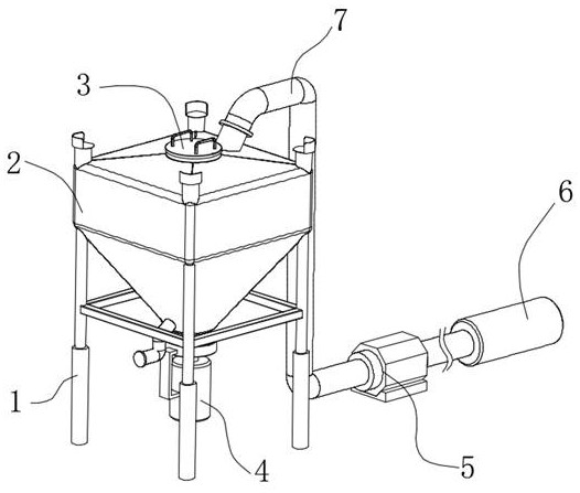
图1为本实用新型的整体结构示意图;Fig. 1 is the overall structure schematic diagram of the present utility model;
图2为本实用新型储存罐内部结构剖视图;2 is a cross-sectional view of the internal structure of the storage tank of the utility model;
图3为本实用新型滤筒与异形杆以及刮层机构之间连接结构示意图;3 is a schematic diagram of the connection structure between the filter cartridge, the special-shaped rod and the scraping layer mechanism of the present invention;
图4为本实用新型滤筒内部结构示意图。Figure 4 is a schematic diagram of the internal structure of the filter cartridge of the present invention.
图中:1、安装架;2、储存罐;3、活动盖;4、电机;5、泵体;6、连接管;7、送水管;8、排液管;9、滤筒;10、转轴;11、橡胶刮板;12、防堵橡胶板;13、异形杆;14、连接柱;15、滤孔。In the figure: 1. Mounting frame; 2. Storage tank; 3. Movable cover; 4. Motor; 5. Pump body; 6. Connecting pipe; 7. Water supply pipe; 8. Drain pipe; 9. Filter cartridge; 10. Rotating shaft; 11. Rubber scraper; 12. Anti-blocking rubber plate; 13. Special-shaped rod; 14. Connecting column; 15. Filter hole.
具体实施方式Detailed ways
为了能够更清楚地理解本实用新型的上述目的、特征和优点,下面结合附图和具体实施方式对本实用新型进行进一步的详细描述。In order to be able to understand the above-mentioned objects, features and advantages of the present invention more clearly, the present invention will be further described in detail below with reference to the accompanying drawings and specific embodiments.
如图1-图4所示的一种卤水持续采集抽取系统装置,包括安装架1,安装架1内侧上方位置安装有储存罐2,储存罐2一侧设置有抽取机构,储存罐2内侧设置有转轴10,转轴10的顶部设置有滤筒9,转轴10一端上方与滤筒9底部转动连接,滤筒9一端上方与储存罐2内侧顶部固定连接,滤筒9内侧底部均开设有多组滤孔15,滤筒9的两侧均滑动安装有异形杆13,且两根异形杆13与滤筒9外壁相贴合,两根异形杆13内侧底部均设置有防堵机构,两根异形杆13底端分别安装在转轴10的两侧,两根异形杆13的两端上方均设置有刮层机构,转轴10一端下方延伸至储存罐2的底部且端部设置有驱动机构,储存罐2一端下方连通安装有排液管8。As shown in FIG. 1-FIG. 4, a brine continuous collection and extraction system device includes an installation frame 1, a
通过设置的安装架1可在储存罐2的外侧进行稳固支撑,滤筒9可便于将卤水的杂质进行分离过滤,致使卤水在后期加工生产过程中能够进行直接使用,同时当转轴10转动时,可驱动异形杆13和刮层机构转动在储存罐2的内部,然后对滤筒9的外侧,以及储存罐2的内壁污垢进行处理。The installed mounting frame 1 can be stably supported on the outside of the
抽取机构包括设置在安装架1一侧的泵体5,泵体5抽吸端连通有连接管6,泵体5排出端连通有送水管7,送水管7远离泵体5的一端连通在储存罐2的内部,泵体5连通电源后通过连接管6的延伸,可将地下卤水抽取,然后通过送水管7输送到储存罐2的内部进行保存。The extraction mechanism includes a
防堵机构均包括对称安装在异形杆13底部的连接柱14,两根连接柱14的顶部共同安装有防堵橡胶板12,防堵橡胶板12的顶部均安装有多组橡胶柱,且多组橡胶柱与滤筒9内侧底部滑动贴合,防堵橡胶板12随着异形杆13的转动,会在滤筒9的底部进行转动,多组橡胶柱可透过滤孔15,将堵塞的滤孔15进行拨动,保持卤水的滤出。The anti-blocking mechanism includes a connecting
刮层机构均包括安装在异形杆13一端上方的橡胶刮板11,橡胶刮板11的一端外壁与储存罐2的内壁滑动贴合,橡胶刮板11的底端与转轴10外壁下方位置相连接,当转轴10转动时,橡胶刮板11可在储存罐2内壁进行刮蹭,将内壁附着的污垢层进行刮蹭。The scraping mechanism includes a
驱动机构包括固定安装在储存罐2底部的电机4,电机4输出轴与转轴10端部固定连接,电机4连接外部电源后可驱动转轴10转动在储存罐2的内部进行使用。The driving mechanism includes a
储存罐2的外形呈正四方形设置,且储存罐2内壁拐角处均呈圆滑面设置,储存罐2顶部中间卡装有活动盖3,活动盖3可从储存罐2的顶部中间打开,后期可以清理滤筒9内部的杂质,正四方形设置的储存罐2可使得相互靠近的两面内壁距离相同,从而橡胶刮板11在使用时能够始终处于贴合接触的状态。The shape of the
工作原理:泵体5连通外部电源后,通过连接管6的设置来抽吸卤水,然后通过一端排出从送水管7处送入到储存罐2的内部,此时电机4从下方带动储存罐2内部的转轴10转动,转轴10一端上方的滤筒9即会将送入的卤水进行分离,杂质通过滤筒9的过滤使其卤水在采集时不会有过多杂质,卤水保留在储存罐2的内侧底部,转轴10在转动的同时会带动两端外侧的异形杆13和橡胶刮板11可分别对滤筒9外壁以及储存罐2内壁相刮,由于储存罐2内部的构造可促使橡胶刮板11能够充分贴合每一面内壁,以此来将附着的污垢层进行刮除,而在异形杆13内侧底部的防堵橡胶板12以及顶部安装的多组橡胶柱可在滤筒9内侧底部进行滑动接触,从而加速滤筒9的流通,避免底部发生堵塞的问题影响卤水排水,后期可通过打开活动盖3用工具将滤筒9内部的杂质进行处理便可。Working principle: After the
以上显示和描述了本实用新型的基本原理、主要特征和本实用新型的优点。本行业的技术人员应该了解,本实用新型不受上述实施例的限制,上述实施例和说明书中描述的只是本实用新型的原理,在不脱离本实用新型精神和范围的前提下本实用新型还会有各种变化和改进,这些变化和改进都落入要求保护的本实用新型的范围内。本实用新型要求的保护范围由所附的权利要求书及其等同物界定。The basic principles, main features and advantages of the present invention have been shown and described above. It should be understood by those skilled in the art that the present invention is not limited by the above-mentioned embodiments, and the above-mentioned embodiments and descriptions describe only the principles of the present invention. There are various changes and improvements that fall within the scope of the claimed invention. The scope of protection claimed by the present invention is defined by the appended claims and their equivalents.
Claims (6)
Priority Applications (1)
| Application Number | Priority Date | Filing Date | Title |
|---|---|---|---|
| CN202220652003.3U CN217538927U (en) | 2022-03-24 | 2022-03-24 | Brine continuously-collecting and extracting system device |
Applications Claiming Priority (1)
| Application Number | Priority Date | Filing Date | Title |
|---|---|---|---|
| CN202220652003.3U CN217538927U (en) | 2022-03-24 | 2022-03-24 | Brine continuously-collecting and extracting system device |
Publications (1)
| Publication Number | Publication Date |
|---|---|
| CN217538927U true CN217538927U (en) | 2022-10-04 |
Family
ID=83429489
Family Applications (1)
| Application Number | Title | Priority Date | Filing Date |
|---|---|---|---|
| CN202220652003.3U Expired - Fee Related CN217538927U (en) | 2022-03-24 | 2022-03-24 | Brine continuously-collecting and extracting system device |
Country Status (1)
| Country | Link |
|---|---|
| CN (1) | CN217538927U (en) |
-
2022
- 2022-03-24 CN CN202220652003.3U patent/CN217538927U/en not_active Expired - Fee Related
Similar Documents
| Publication | Publication Date | Title |
|---|---|---|
| CN211141621U (en) | Sedimentation tank | |
| CN209500965U (en) | A filter device for chemical industry | |
| CN212866128U (en) | Hydraulic engineering desilting device | |
| CN218174729U (en) | Heavy metal separation and recovery device for electroplating wastewater | |
| CN207786122U (en) | A kind of sewage treatment equipment | |
| CN115608052A (en) | A sedimentation system and sedimentation method for environmental protection industrial sewage treatment | |
| CN220110561U (en) | Collecting assembly for sludge treatment | |
| CN221014819U (en) | A wastewater utilization device based on urban life discharge | |
| CN222715884U (en) | A water diversion device | |
| CN218794067U (en) | A sludge cleaning device for a sludge sedimentation tank | |
| CN116356862B (en) | Drainage device for building construction and use method thereof | |
| CN218779065U (en) | Cleaning device based on plating solution in plating bath | |
| CN219558801U (en) | Central transmission mud scraper for sewage treatment | |
| CN115317973B (en) | Medical wastewater disinfection treatment equipment capable of separating waste materials | |
| CN207694419U (en) | A kind of efficient vertical sloping plate deposition machine | |
| CN218608193U (en) | A starch separation mechanism for potato starch production | |
| CN218853535U (en) | High-efficient environmental protection sedimentation tank for sewage treatment | |
| CN214994217U (en) | Intelligent desilting device in river course | |
| CN214436742U (en) | A kind of sedimentation tank for soil and water conservation | |
| CN211752984U (en) | A scum collection equipment for sewage treatment | |
| CN212914685U (en) | Waste water treatment device for papermaking processing | |
| CN116196669A (en) | Energy-saving sewage treatment equipment | |
| CN116022986A (en) | A sludge thickening device | |
| CN222641469U (en) | Quick dewatering equipment is used in environmental protection engineering | |
| CN212924487U (en) | Sewage oil removal device |
Legal Events
| Date | Code | Title | Description |
|---|---|---|---|
| GR01 | Patent grant | ||
| GR01 | Patent grant | ||
| CF01 | Termination of patent right due to non-payment of annual fee |
Granted publication date: 20221004 |
|
| CF01 | Termination of patent right due to non-payment of annual fee |