Energy-conserving housing construction drainage device
Technical Field
The utility model relates to an energy-conserving housing construction drainage technical field specifically is an energy-conserving housing construction drainage device.
Background
By adopting the technologies of aluminum alloy external sunshade roller shutter, hollow glass, reclaimed water recycling, floor type electric heating and the like, and using a novel energy-saving enclosure system and comprehensive energy-saving technical measures, the energy consumption of house heating in a heating area is reduced, the energy-saving target specified by the state is achieved, a house with good living function and environmental quality is called an energy-saving house, and the drainage device is a whole formed by combining facilities of drainage collection, transportation, water quality treatment, discharge and the like in a certain mode.
Most of drainage pipelines of energy-saving house buildings in the market are of an integrated structure in use, so that the pipeline is disassembled and replaced by consuming longer time and more manpower, meanwhile, the drainage pipeline does not have an over-filtering cleaning structure, and the drainage pipeline is easy to block for a long time.
SUMMERY OF THE UTILITY MODEL
The utility model aims at providing an energy-conserving housing construction drainage device to solve energy-conserving housing construction drainage device in the market that proposes in the above-mentioned background art in that drainage pipe is the integral structure for the most part in use, consequently the dismantlement of pipeline is changed and need be consumeed longer time and more manpower, and drainage pipe does not have simultaneously and filters the clearance structure, easily causes the problem of drainage pipe jam for a long time.
In order to achieve the above object, the utility model provides a following technical scheme: the utility model provides an energy-conserving housing construction drainage device, includes row's of sewer pipe, lower drain pipe, spacing collection mechanism, block filtering mechanism and convenient dismouting mechanism, the lower extreme of last drain pipe is provided with lower drain pipe, and lower drain pipe's lower extreme is provided with spacing collection mechanism, the front end surface of going up the drain pipe is provided with block filtering mechanism, and goes up the right side of drain pipe and be provided with convenient dismouting mechanism, convenient dismouting mechanism is including sealed pad, outer panel, fixture block, spring and built-in groove, and the right-hand outer panel that is provided with of sealed pad, the inside block of outer panel has the fixture block, and the left end of fixture block is provided with the spring, the outside of spring is provided with the built-in groove.
Furthermore, the fixture block and the built-in groove form an elastic structure through a spring, and the fixture block is embedded in the outer side plate.
Furthermore, the outer side plate is fixedly connected with the lower drainage pipe, and the outer side plate is attached to the upper drainage pipe.
Further, spacing collection mechanism includes chassis, fluting, header tank, handle, first pedestal, first rotary rod and mounting panel, and the side middle part of chassis is provided with the fluting, the inside of chassis is provided with the header tank, and the right side middle part of header tank is fixed with the handle, the front end of chassis is provided with the primary shaft frame, and the left side of primary shaft frame is provided with first rotary rod, the both sides below of chassis is fixed with the mounting panel.
Furthermore, the chassis forms a rotating structure through a first shaft bracket and a first rotating rod, and the first rotating rod is attached to the water collecting tank.
Furthermore, block filtering mechanism includes the filter cartridge, draws handle, second rotary rod and second shaft frame, and is fixed with above the front end of filter cartridge and draws the handle, the laminating of the front end below of filter cartridge has the second rotary rod, and the lower extreme of second rotary rod is provided with the second shaft frame.
Furthermore, the filter box is embedded in the upper drainage pipe, and the filter box is fixedly connected with the pull handle.
Compared with the prior art, the beneficial effects of the utility model are that: this energy-conserving housing construction drainage device, the filter cartridge is effectual filters debris, when the filter cartridge needs to be cleared up, the user rotates the second rotary rod and separates with the filter cartridge front end, thereby can effectually take out the filter cartridge and clear away its inside debris, clear away the back again with the filter cartridge block in last drain pipe inside, rotate the second rotary rod again and with the laminating of filter cartridge front end can, because the fixture block passes through the spring and constitutes elastic construction with built-in groove, the user inwards presses the fixture block, thereby can effectually separate outer panel and fixture block, be convenient for directly come out outer panel and drain pipe translation, thereby separate with last drain pipe.
Through the setting of spacing collection mechanism, the drain pipe is linked together with the chassis, therefore energy-conserving house building collect rivers through last drain pipe with drain pipe finally can fall into the inside header tank of chassis, be convenient for collect the utilization to natural water, the user rotates first rotary rod and laminates with the header tank front end, can effectually carry on spacingly to the header tank, rotate first rotary rod and with the separation of header tank front end, the header tank of being convenient for take out.
Through block filtering mechanism's setting, because the filter cartridge gomphosis is inside in last drain pipe, and carry on spacingly through second rotary rod and second shaft frame to the filter cartridge, the filter cartridge is effectual to debris filter, when the filter cartridge needs to be cleared up, the user rotates the second rotary rod and separates with the filter cartridge front end, thereby can effectually take out the filter cartridge and clear away its inside debris, clear away the back again with the filter cartridge block in last drain pipe inside, again with the second rotary rod rotate and with the laminating of filter cartridge front end can.
Through the setting of convenient dismouting mechanism, drainage pipe in the device divide into drain pipe and drain pipe down, the user can be dismantled some water pipes alone according to the demand, because the fixture block passes through the spring and constitutes elastic construction with built-in groove, the user inwards presses the fixture block, thereby can effectually separate outer panel and fixture block, be convenient for directly come out outer panel and drain pipe translation down, thereby with the drain pipe separation of going up, the drain pipe of going up can adopt the bolt to be connected it with energy-conserving house building, sealed setting up of filling up has increased the leakproofness between drain pipe and the drain pipe down, reduce the possibility that rivers flow.
Drawings
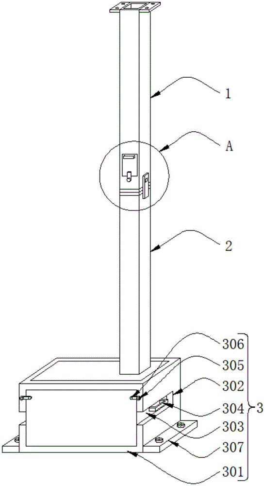
FIG. 1 is a schematic perspective view of the present invention;
FIG. 2 is a schematic view of a partial enlarged structure at A in FIG. 1 according to the present invention;
fig. 3 is a schematic view of the local front view internal structure of the present invention.
In the figure: 1. an upper drainage pipe; 2. a lower drainage pipe; 3. a limiting and collecting mechanism; 301. a chassis; 302. slotting; 303. a water collection tank; 304. a handle; 305. a first pedestal; 306. a first rotating lever; 307. mounting a plate; 4. clamping the filtering mechanism; 401. a filter cartridge; 402. pulling a handle; 403. a second rotating lever; 404. a second shaft frame; 5. a convenient disassembly and assembly mechanism; 501. a gasket; 502. an outer panel; 503. a clamping block; 504. a spring; 505. a built-in groove.
Detailed Description
As shown in fig. 1, an energy-saving house building drainage device comprises: the lower end of the upper drainage pipe 1 is provided with a lower drainage pipe 2, the lower end of the lower drainage pipe 2 is provided with a limiting collection mechanism 3, the limiting collection mechanism 3 comprises a base frame 301, a groove 302, a water collection tank 303, a handle 304, a first shaft frame 305, a first rotating rod 306 and a mounting plate 307, the middle of the side of the base frame 301 is provided with the groove 302, the water collection tank 303 is arranged inside the base frame 301, the handle 304 is fixed in the middle of the right side of the water collection tank 303, the front end of the base frame 301 is provided with the first shaft frame 305, the left side of the first shaft frame 305 is provided with the first rotating rod 306, the mounting plate 307 is fixed below the two sides of the base frame 301, the base frame 301 forms a rotating structure through the first shaft frame 305 and the first rotating rod 306, the first rotating rod 306 is attached to the water collection tank 303, the lower drainage pipe 2 is communicated with the base frame 301, therefore, water collected by the energy-saving building can finally fall into the water collection tank 303 through the upper drainage pipe 1 and the lower drainage pipe 2, natural water can be collected and utilized, the rotating rod 306 can be attached to the front end of the water collection tank 303 effectively, and the first water collection tank 303 can be conveniently extracted.
As shown in fig. 2-3, in the energy-saving house building drainage device, the front end surface of an upper drainage pipe 1 is provided with a clamping filter mechanism 4, the right side of the upper drainage pipe 1 is provided with a convenient assembly and disassembly mechanism 5, the clamping filter mechanism 4 comprises a filter box 401, a pull handle 402, a second rotating rod 403 and a second shaft bracket 404, the pull handle 402 is fixed above the front end of the filter box 401, the second rotating rod 403 is attached below the front end of the filter box 401, the lower end of the second rotating rod 403 is provided with the second shaft bracket 404, the filter box 401 is embedded in the upper drainage pipe 1, the filter box 401 and the pull handle 402 are fixedly connected, because the filter box 401 is embedded in the upper drainage pipe 1 and limits the filter box 401 through the second rotating rod 403 and the second shaft bracket 404, the filter box 401 effectively filters sundries, when the filter box 401 needs to be cleaned, a user rotates the second rotating rod 403 and separates from the front end of the filter box 401, therefore, the filter box 401 can be effectively drawn out to remove sundries in the filter box 401, the filter box 401 is clamped in the upper water drainage pipe 1 after being cleaned, the second rotating rod 403 is rotated again and is attached to the front end of the filter box 401, the convenient and fast dismounting mechanism 5 comprises a sealing gasket 501, an outer plate 502, a clamping block 503, a spring 504 and an inner groove 505, the outer plate 502 is arranged on the right side of the sealing gasket 501, the clamping block 503 is clamped in the outer plate 502, the spring 504 is arranged at the left end of the clamping block 503, the inner groove 505 is arranged on the outer side of the spring 504, the clamping block 503 forms an elastic structure with the inner groove 505 through the spring 504, the clamping block 503 is embedded in the outer plate 502, the outer plate 502 is fixedly connected with the lower water drainage pipe 2, the outer plate 502 is attached to the upper water drainage pipe 1, the drainage pipe in the device is divided into the upper water drainage pipe 1 and the lower water drainage pipe 2, the user can dismantle certain part water pipe alone according to the demand, because fixture block 503 passes through spring 504 and built-in groove 505 constitutes elastic structure, the user inwards presses fixture block 503, thereby can effectually separate outer panel 502 and fixture block 503, be convenient for directly come out outer panel 502 and drain pipe 2 translation down, thereby with the separation of drain pipe 1, drain pipe 1 can adopt the bolt to be connected it with energy-conserving housing construction, the setting up of sealed pad 501 has increased the leakproofness between drain pipe 1 and the drain pipe 2 down, reduce the possibility that rivers flow.
In summary, in the drainage apparatus for energy-saving building construction, the lower drainage pipe 2 is firstly communicated with the bottom frame 301, so that water collected by the energy-saving building construction finally falls into the water collection tank 303 inside the bottom frame 301 through the upper drainage pipe 1 and the lower drainage pipe 2, which is convenient for collecting and utilizing natural water, a user rotates the first rotating rod 306 and attaches to the front end of the water collection tank 303, the water collection tank 303 can be limited, the first rotating rod 306 rotates and separates from the front end of the water collection tank 303, which is convenient for drawing out the water collection tank 303, the drainage pipe in the apparatus is divided into the upper drainage pipe 1 and the lower drainage pipe 2, the user can separately detach a certain part of the drainage pipe according to requirements, because the clamping block 503 forms an elastic structure with the built-in groove 505 through the spring 504, the user presses the clamping block 503 inwards, thereby separating the outer side plate 502 from the clamping block 503, which is convenient for directly translating the outer side plate 502 and the lower drainage pipe 2 out, thereby separating from the upper drainage pipe 1, the upper drainage pipe 1 can be connected with the energy-saving building construction by the bolt, the upper drainage pipe 1 can be detached from the energy-saving building construction, the filtering box 401 can be effectively removed by the filtering box 401 by the second filtering box 401 after the filtering box is rotated and the filtering box 401 is removed by the filtering box 401.