CN217526807U - Dust collecting device for pulse dust collector - Google Patents

Dust collecting device for pulse dust collector Download PDF

Info

Publication number
CN217526807U
CN217526807U CN202221165686.6U CN202221165686U CN217526807U CN 217526807 U CN217526807 U CN 217526807U CN 202221165686 U CN202221165686 U CN 202221165686U CN 217526807 U CN217526807 U CN 217526807U
Authority
CN
China
Prior art keywords
dust collecting
water
fixed
dust
collecting box
Prior art date
Legal status (The legal status is an assumption and is not a legal conclusion. Google has not performed a legal analysis and makes no representation as to the accuracy of the status listed.)
Expired - Fee Related
Application number
CN202221165686.6U
Other languages
Chinese (zh)
Inventor
宋春巧
李红丽
李嘉诚
李鸿伟
吴亚丽
邬华韬
Current Assignee (The listed assignees may be inaccurate. Google has not performed a legal analysis and makes no representation or warranty as to the accuracy of the list.)
Zhumadian City Longshan General Machinery Co ltd
Original Assignee
Zhumadian City Longshan General Machinery Co ltd
Priority date (The priority date is an assumption and is not a legal conclusion. Google has not performed a legal analysis and makes no representation as to the accuracy of the date listed.)
Filing date
Publication date
Application filed by Zhumadian City Longshan General Machinery Co ltd filed Critical Zhumadian City Longshan General Machinery Co ltd
Priority to CN202221165686.6U priority Critical patent/CN217526807U/en
Application granted granted Critical
Publication of CN217526807U publication Critical patent/CN217526807U/en
Expired - Fee Related legal-status Critical Current
Anticipated expiration legal-status Critical

Links

Images

Landscapes

  • Cleaning In General (AREA)

Abstract

本实用新型公开了一种脉冲除尘器用收尘装置,包括脉冲除尘器和收尘箱,脉冲除尘器底部固定设有灰斗,灰斗底部分别连接于收尘箱顶部,收尘箱位于脉冲除尘器正下方,收尘箱内部倾斜设有震动分料板,收尘箱左右两端中部分别固定设有固定块,固定块顶部固定设有弹簧,弹簧顶端分别固定连接于震动分料板左右两端,震动分料板左右两侧底部分别固定设有震动电机,震动分料板中部设有筛网,收尘箱底部固定设有水溶箱,水溶箱右侧固定设有水箱,水箱顶部固定设有水泵,水溶箱内部固定于侧壁设有固定管,水溶箱底部转动设有螺旋送料龙。本实用新型与现有技术相比的优点在于:可以将灰斗内的废料进行震动分筛收集,对粉尘进行水溶送料处理。

Figure 202221165686

The utility model discloses a dust collecting device for a pulse dust collector, which comprises a pulse dust collector and a dust collecting box. An ash hopper is fixedly arranged at the bottom of the pulse dust collector, the bottom of the ash hopper is respectively connected to the top of the dust collecting box, and the dust collecting box is located in the pulse dust collecting box. Right below the dust collector, there is a vibrating distributing plate inside the dust collecting box, fixing blocks are respectively fixed in the middle of the left and right ends of the dust collecting box, a spring is fixed on the top of the fixing block, and the top of the spring is fixedly connected to the left and right sides of the vibration distributing plate respectively. The bottom of the vibration distribution plate is fixed with a vibration motor, the middle of the vibration distribution plate is equipped with a screen, the bottom of the dust collecting box is fixed with a water soluble box, the right side of the water soluble box is fixed with a water tank, and the top of the water tank is fixed with a water tank. There is a water pump, the inside of the water-soluble tank is fixed on the side wall with a fixed pipe, and the bottom of the water-soluble tank is rotated with a screw feeding dragon. Compared with the prior art, the utility model has the advantages that the wastes in the ash hopper can be collected by vibrating screening, and the dust can be treated by water-soluble feeding.

Figure 202221165686

Description

Dust collecting device for pulse dust collector
Technical Field
The utility model relates to a pulse dust collector field specifically indicates a dust arrester installation for pulse dust collector.
Background
When the dust-containing gas enters the dust remover from the air inlet and touches the inclined plate and the baffle plate in the middle of the air inlet and the air outlet, the gas flow turns to flow into the dust hopper, and simultaneously the gas flow speed is slowed down, so that coarse-particle dust in the gas directly flows into the dust hopper due to the inertia effect. Fine, dry and non-fibrous dust moves upwards to be adsorbed by the filter bag, and then the pulse valve is opened through the control valve to blow off the dust on the cloth bag, so that the filtering effect of the filter bag is ensured.
But when carrying out the inside dust processing of ash bucket, particulate matter and dust thing are all from the unified collection of ash bucket bottom, and subsequent processing is comparatively troublesome, and a large amount of dusts fly up when the ash bucket clearance, shelter from the sight and influence the security of work and also bring the dust pollution when also, influence the staff healthy. Therefore, the dust collecting device for the pulse dust collector is provided.
SUMMERY OF THE UTILITY MODEL
The to-be-solved technical problem of the utility model is to solve the above-mentioned not enough, provide one kind can shake the waste material in the ash bucket and divide the sieve to collect, carry out a dust arrester installation for pulse dust collector that water-soluble pay-off was handled to the dust.
In order to solve the technical problem, the utility model provides a technical scheme does: the utility model provides a dust arrester installation for pulse dust collector, includes pulse dust collector and dust collection box, the fixed ash bucket that is equipped with in pulse dust collector bottom, the ash bucket bottom is connected respectively in the roof portion that gathers dust, the dust collection box is located under the pulse dust collector, the inside slope of dust collection box is equipped with vibrations branch flitch, the fixed block that is equipped with respectively in both ends middle part about the dust collection box, the fixed spring that is equipped with in fixed block top, spring top fixed connection is in vibrations branch flitch both ends about respectively, vibrations divide flitch left and right sides bottom to fix respectively and be equipped with shock dynamo, vibrations divide the flitch middle part to be equipped with the screen cloth, the fixed water-soluble case that is equipped with in dust collection box bottom, the fixed water tank that is equipped with in water-soluble case right side, the fixed water tank top is equipped with the water pump, the inside lateral wall that is fixed in water-soluble case is equipped with fixed pipe, water-soluble case bottom rotates and is equipped with spiral pay-off dragon.
Furthermore, the left side and the right side of the vibration material distribution plate are respectively and fixedly provided with a sliding block, and the left side and the right side of the dust collection box are provided with sliding grooves matched with the sliding blocks.
Furthermore, the right end of the vibration material distribution plate is located on the right wall of the dust collection box and is fixedly provided with a particle feed opening, the left side of the particle feed opening is fixedly provided with a connection cloth bag, and the other end of the connection cloth bag is connected to the vibration material distribution plate.
Furthermore, a material guide plate is arranged below the dust collection box, a dust feed opening is fixedly formed in the middle of the material guide plate, and the bottom of the dust feed opening is fixedly connected to the top of the water soluble box.
Furthermore, fixed being equipped with a plurality of water shower nozzles on the fixed pipe, the water pump left and right sides all is equipped with the water pipe, the water piping connection on water pump right side is inside the water tank, the left water piping connection of water pump is in the fixed pipe of water-soluble incasement portion.
Further, the dragon left end of spiral pay-off is located water-soluble case outside, the fixed bin outlet that is equipped with in the dragon left end bottom of spiral pay-off, the dragon left end pivot department of spiral pay-off is equipped with motor and fixed connection in motor output shaft end.
Compared with the prior art, the utility model the advantage lie in: the waste material that need carry out the collection processing to getting into the ash bucket carries out further separation and gathers dust, carries out further screening with inside dust thing and particulate matter, collects dustless particulate matter alone to and carry out further water-soluble processing to the dust, form the jelly and carry out the pay-off and collect, reduce the emergence of the dust situation of dancing in the air and reduce dust pollution, reduce the practitioner risk, improve the work efficiency of the collection processing of pulse dust collector waste material simultaneously, have fine dust collection effect.
Drawings
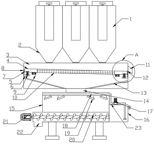
Fig. 1 is a schematic structural view of the present invention.
Fig. 2 is an enlarged schematic view of a structure in fig. 1 according to the present invention.
As shown in the figure: 1. a pulse dust collector; 2. an ash hopper; 3. a dust collection box; 4. vibrating the material distributing plate; 5. a fixed block; 6. a spring; 7. a slider; 8. a chute; 9. vibrating a motor; 10. a screen mesh; 11. a particle feed opening; 12. connecting the cloth bags; 13. a stock guide; 14. a dust feed opening; 15. a water dissolving tank; 16. a water tank; 17. a water pump; 18. a fixed tube; 19. a water spray head; 20. a spiral feeding dragon; 21. a motor; 22. a discharge outlet; 23. a water pipe.
Detailed Description
In order to make the technical problem, technical solution and advantageous effects to be solved by the present invention more clearly understood, the following description is made in conjunction with the accompanying drawings and embodiments for further detailed description, and it should be understood that the specific embodiments described herein are only used for explaining the present invention, and are not used for limiting the present invention.
In the description of the present invention, it is to be understood that the terms "center", "lateral", "upper", "lower", "left", "right", "vertical", "horizontal", "top", "bottom", "inner", "outer", and the like indicate orientations or positional relationships based on the orientations or positional relationships shown in the drawings, and are only for convenience of description and simplicity of description, but do not indicate or imply that the device or element referred to must have a particular orientation, be constructed and operated in a particular orientation, and therefore, are not to be construed as limiting the present invention. Furthermore, the terms "first", "second" and "first" are used for descriptive purposes only and are not to be construed as indicating or implying relative importance or to implicitly indicate the number of technical features indicated. Thus, a feature defined as "first" or "second" may explicitly or implicitly include one or more of that feature. In the description of the present invention, "a plurality" means two or more unless otherwise specified. Furthermore, the term "comprises" and any variations thereof is intended to cover non-exclusive inclusions.
In the description of the present invention, it is to be noted that the term "connected" is to be interpreted broadly, for example, as a fixed connection, a detachable connection, or an integral connection, unless otherwise explicitly stated or limited, and those skilled in the art can understand the specific meaning of the above terms in the present invention in a specific case.
The present invention will be described in further detail with reference to the accompanying drawings.
Combine the attached drawing, a dust arrester installation for pulse dust collector, including pulse dust collector 1 and dust collection box 3, 1 fixed ash bucket 2 that is equipped with in bottom of pulse dust collector, 2 bottoms of ash buckets are connected respectively in dust collection box 3 tops, dust collection box 3 is located under pulse dust collector 1, the inside slope of dust collection box 3 is equipped with vibrations and divides flitch 4, dust collection box 3 is controlled both ends middle part and is fixed block 5 respectively, the fixed spring 6 that is equipped with in fixed block 5 top, 6 top of spring fixed connection respectively divide flitch 4 left and right sides in vibrations, vibrations divide the flitch 4 left and right sides to fix respectively and are equipped with slider 7, the dust collection box 3 left and right sides is equipped with spout 8 with slider 7 matched with. The vibrating material distributing plate is used for driving the vibrating material distributing plate 4 to vibrate and separate dust and particles above the vibrating material distributing plate to distribute materials.
The dust collecting box is characterized in that the bottom of the left side and the bottom of the right side of the vibration material distributing plate 4 are respectively and fixedly provided with a vibration motor 9, the middle of the vibration material distributing plate 4 is provided with a screen 10, the right end of the vibration material distributing plate 4 is positioned on the right wall of the dust collecting box 3 and is fixedly provided with a particle feed opening 11, the left side of the particle feed opening 11 is fixedly provided with a connecting cloth bag 12, and the other end of the connecting cloth bag 12 is connected to the vibration material distributing plate 4. The particles are prevented from falling down when moving to the right, and the separation is ensured to be completed. A material guide plate 13 is arranged below the dust collection box 3, a dust feed opening 14 is fixedly arranged in the middle of the material guide plate 13, and the bottom of the dust feed opening 14 is fixedly connected to the top of the water soluble box 15. The particle feed opening 11 and the dust feed opening 14 are used for separate feeding of particles and separate feeding of dust respectively, and are collected and processed respectively after separation.
The fixed water-soluble case 15 that is equipped with in dust collection case 3 bottom, the fixed water tank 16 that is equipped with in water-soluble case 15 right side, the fixed water pump 17 that is equipped with in water tank 16 top, the inside lateral wall that is fixed in of water-soluble case 15 is equipped with fixed pipe 18, fixed being equipped with a plurality of water spray heads 19 on the fixed pipe 18, the water pump 17 left and right sides all is equipped with water pipe 23, the water pipe 23 on water pump 17 right side is connected inside water tank 16, the left water pipe 23 of water pump 17 is connected in the fixed pipe 18 of water-soluble 15 insides. The device is used for water-soluble treatment of dust, and is convenient for subsequent collection, reduction of dust flying and pollution reduction.
The bottom of the water-soluble box 15 is rotatably provided with a spiral feeding dragon 20. 20 left ends of spiral pay-off dragon are located water-soluble case 15 outsidely, 20 left end bottoms of spiral pay-off dragon are fixed and are equipped with bin outlet 22, 20 left end pivots departments of spiral pay-off dragon are equipped with motor 21 and fixed connection in motor 21 output shaft end. The device is used for discharging and feeding the waste after dust is dissolved in water.
The utility model discloses a theory of operation: the utility model discloses when specifically implementing, the waste gas that the pulse dust remover produced when producing the operation removes dust, at first receive particulate matter under the action of gravity and get into the top of collecting the inside vibrations branch flitch 4 of dirt case 3 through ash bucket 2, vibrating motor 9 drives vibrations branch flitch 4 vibrations after the work, adnexed dust and particulate matter separation on the particulate matter, the dust moves down through screen cloth 10, the particulate matter then moves towards the right side and gets into granule feed opening 11 and carry out the unloading and collect, when pulse dust remover 1 closes and begins to clear up the sack, dust on the sack and few particulate matter then fall inside ash bucket 2, divide the material through vibrations branch flitch 4, the dust thing falls to get into water-soluble box 15 inside through dust feed opening 14 after collecting box 3 after through stock guide 13 guide, pump 17 work back extraction water tank 16 inside, lead to pipe 23 carry inside fixed pipe 18, spout through water head 19 again and combine with the dust, form colloid or oar liquid and get into inside the spiral feeding dragon 20 of bottom, motor 21 drives spiral feeding dragon 20 after the work and rotates, it collects and handles the follow-up with the bin outlet 22 and processes follow-up.
The present invention and the embodiments thereof have been described above, but the description is not limited thereto, and the embodiment shown in the drawings is only one of the embodiments of the present invention, and the actual structure is not limited thereto. In summary, it should be understood that those skilled in the art should also understand the scope of the present invention without inventively designing the similar structure and embodiments of the present invention without departing from the spirit of the present invention.

Claims (6)

1.一种脉冲除尘器用收尘装置,其特征在于:包括脉冲除尘器(1)和收尘箱(3),所述脉冲除尘器(1)底部固定设有灰斗(2),所述灰斗(2)底部分别连接于收尘箱(3)顶部,所述收尘箱(3)位于脉冲除尘器(1)正下方,所述收尘箱(3)内部倾斜设有震动分料板(4),所述收尘箱(3)左右两端中部分别固定设有固定块(5),所述固定块(5)顶部固定设有弹簧(6),所述弹簧(6)顶端分别固定连接于震动分料板(4)左右两端,所述震动分料板(4)左右两侧底部分别固定设有震动电机(9),所述震动分料板(4)中部设有筛网(10),所述收尘箱(3)底部固定设有水溶箱(15),所述水溶箱(15)右侧固定设有水箱(16),所述水箱(16)顶部固定设有水泵(17),所述水溶箱(15)内部固定于侧壁设有固定管(18),所述水溶箱(15)底部转动设有螺旋送料龙(20)。1. A dust collecting device for a pulse dust collector, characterized in that it comprises a pulse dust collector (1) and a dust collecting box (3), an ash hopper (2) is fixedly arranged at the bottom of the pulse dust collector (1), and the The bottom of the ash hopper (2) is respectively connected to the top of the dust collecting box (3), the dust collecting box (3) is located directly below the pulse dust collector (1), and the inside of the dust collecting box (3) is inclined with vibration distribution Plate (4), the middle of the left and right ends of the dust collecting box (3) is respectively fixed with a fixing block (5), the top of the fixing block (5) is fixed with a spring (6), the top of the spring (6) They are respectively fixedly connected to the left and right ends of the vibration distributing plate (4), the bottoms of the left and right sides of the vibration distributing plate (4) are respectively fixed with vibration motors (9), and the middle part of the vibration distributing plate (4) is provided with A screen (10), a water soluble box (15) is fixedly arranged at the bottom of the dust collecting box (3), a water tank (16) is fixedly arranged on the right side of the water soluble box (15), and a water tank (16) is fixedly arranged at the top. There is a water pump (17), the inside of the water dissolving tank (15) is fixed on the side wall with a fixed pipe (18), and the bottom of the water dissolving tank (15) is rotated with a screw feeding dragon (20). 2.根据权利要求1所述的一种脉冲除尘器用收尘装置,其特征在于:所述震动分料板(4)左右两侧分别固定设有滑块(7),所述收尘箱(3)左右两侧设有与滑块(7)相配合的滑槽(8)。2. A dust collecting device for a pulse dust collector according to claim 1, characterized in that: sliders (7) are respectively fixed on the left and right sides of the vibration distributing plate (4), and the dust collecting box ( 3) The left and right sides are provided with chute (8) matched with the slider (7). 3.根据权利要求1所述的一种脉冲除尘器用收尘装置,其特征在于:所述震动分料板(4)右端位于收尘箱(3)右壁上固定设有颗粒下料口(11),所述颗粒下料口(11)左侧固定设有连接布袋(12),所述连接布袋(12)另一端连接于震动分料板(4)。3. A dust collecting device for a pulse dust collector according to claim 1, characterized in that: the right end of the vibrating distributing plate (4) is located on the right wall of the dust collecting box (3) and is fixedly provided with a particle discharging port ( 11), a connecting cloth bag (12) is fixedly arranged on the left side of the particle feeding opening (11), and the other end of the connecting cloth bag (12) is connected to the vibration distributing plate (4). 4.根据权利要求1所述的一种脉冲除尘器用收尘装置,其特征在于:所述收尘箱(3)内部下方设有导料板(13),所述导料板(13)中部固定设有灰尘下料口(14),所述灰尘下料口(14)底部固定连接于水溶箱(15)顶部。4. A dust collecting device for a pulse dust collector according to claim 1, characterized in that: a material guide plate (13) is arranged under the inside of the dust collecting box (3), and a middle part of the material guide plate (13) is provided. A dust discharge port (14) is fixedly arranged, and the bottom of the dust discharge port (14) is fixedly connected to the top of the water soluble box (15). 5.根据权利要求1所述的一种脉冲除尘器用收尘装置,其特征在于:所述固定管(18)上固定设有若干水喷头(19),所述水泵(17)左右两侧均设有水管(23),所述水泵(17)右侧的水管(23)连接于水箱(16)内部,所述水泵(17)左侧的水管(23)连接于水溶箱(15)内部的固定管(18)。5 . The dust collecting device for a pulse dust collector according to claim 1 , wherein a plurality of water nozzles ( 19 ) are fixedly arranged on the fixed pipe ( 18 ), and the left and right sides of the water pump ( 17 ) are arranged on both sides. 6 . A water pipe (23) is provided, the water pipe (23) on the right side of the water pump (17) is connected to the inside of the water tank (16), and the water pipe (23) on the left side of the water pump (17) is connected to the water tank (15) inside. Fixed tube (18). 6.根据权利要求1所述的一种脉冲除尘器用收尘装置,其特征在于:所述螺旋送料龙(20)左端位于水溶箱(15)外部,所述螺旋送料龙(20)左端底部固定设有排料口(22),所述螺旋送料龙(20)左端转轴处设有电机(21)且固定连接于电机(21)输出轴端。6 . The dust collecting device for a pulse dust collector according to claim 1 , wherein the left end of the screw feeding dragon (20) is located outside the water soluble box (15), and the bottom of the left end of the screw feeding dragon (20) is fixed at the bottom. 7 . A discharge port (22) is provided, and a motor (21) is provided at the left end rotating shaft of the screw feeding dragon (20) and is fixedly connected to the output shaft end of the motor (21).
CN202221165686.6U 2022-05-16 2022-05-16 Dust collecting device for pulse dust collector Expired - Fee Related CN217526807U (en)

Priority Applications (1)

Application Number Priority Date Filing Date Title
CN202221165686.6U CN217526807U (en) 2022-05-16 2022-05-16 Dust collecting device for pulse dust collector

Applications Claiming Priority (1)

Application Number Priority Date Filing Date Title
CN202221165686.6U CN217526807U (en) 2022-05-16 2022-05-16 Dust collecting device for pulse dust collector

Publications (1)

Publication Number Publication Date
CN217526807U true CN217526807U (en) 2022-10-04

Family

ID=83436519

Family Applications (1)

Application Number Title Priority Date Filing Date
CN202221165686.6U Expired - Fee Related CN217526807U (en) 2022-05-16 2022-05-16 Dust collecting device for pulse dust collector

Country Status (1)

Country Link
CN (1) CN217526807U (en)

Cited By (1)

* Cited by examiner, † Cited by third party
Publication number Priority date Publication date Assignee Title
CN118106127A (en) * 2024-02-22 2024-05-31 华能国际电力股份有限公司丹东电厂 An electrostatic precipitator dust collecting device

Cited By (1)

* Cited by examiner, † Cited by third party
Publication number Priority date Publication date Assignee Title
CN118106127A (en) * 2024-02-22 2024-05-31 华能国际电力股份有限公司丹东电厂 An electrostatic precipitator dust collecting device

Similar Documents

Publication Publication Date Title
CN209953260U (en) Rice processing is with dust collector who has ground rice recovery function
CN212349394U (en) Concentrator that screening effect is good
CN208555030U (en) A kind of rotation vibration grain cleaning screen
CN213824040U (en) Dust extraction is used in welding
CN212881524U (en) Dust removal pipeline filter equipment
CN218924207U (en) Pulse dust collector for bone grain production
CN210647207U (en) Take pendulous device's maize granule sieve separator
CN221493300U (en) Dust-free sieve powder recovery device
CN218307031U (en) Filter cylinder type rapid dust removal purification device
CN219003760U (en) Horizontal wind material separator
CN217747993U (en) Complex frequency vibrating screen capable of being overturned for multiple times
CN215505995U (en) Dust remover for potassium sulfate processing and dust removal mechanism and cleaning mechanism thereof
CN216572021U (en) Novel fodder removes dust device
CN214642859U (en) Shot cleaning type shot blasting machine
CN210701161U (en) Environment-friendly dust removal winnowing machine
CN105129431B (en) Micro mist wax automatic production line
CN202129220U (en) Air separation sieve device
CN223587972U (en) A material dust collector for feed processing
CN213591252U (en) A kind of iron scrap recovery device for iron and steel processing
CN215918216U (en) Soybean breeding edulcoration device
CN224208767U (en) Powder processing apparatus for powder production
CN207288897U (en) A kind of lead-power machine
CN219519600U (en) Glossy ganoderma spore powder sieving mechanism
CN222491012U (en) Agricultural seed sieving mechanism
CN221847734U (en) A material screening structure for civil construction

Legal Events

Date Code Title Description
GR01 Patent grant
GR01 Patent grant
CF01 Termination of patent right due to non-payment of annual fee

Granted publication date: 20221004