Energy-conserving curing means is used in construction
Technical Field
The utility model relates to a maintenance of equipment technical field especially relates to an energy-conserving curing means is used in construction.
Background
The building construction refers to production activities in the engineering construction implementation stage, and is a construction process of various buildings, and after concrete is poured on the ground and the wall of the building, in order to prevent cracks from being generated due to over-dry concrete surface, the concrete needs to be subjected to watering maintenance, so that special maintenance equipment can be used.
When the existing concrete surface is subjected to watering maintenance, the water pipe is usually manually held to spray water on the concrete surface, the water pipe can be damaged due to the fact that the water impact force of the water pipe is high, the water pipe can spray water, and the water absorption amount of the concrete is small, so that a large amount of water resource waste can be caused.
Based on this, we propose an energy-conserving curing means for construction.
SUMMERY OF THE UTILITY MODEL
The utility model aims at solving the defects existing in the prior art and providing an energy-saving maintenance device for building construction.
In order to achieve the above purpose, the utility model adopts the following technical scheme:
the utility model provides an energy-conserving curing means is used in construction, includes the base, base upper end fixedly connected with storage water tank, base upper end fixedly connected with installation pole, the spout has been seted up to installation pole lateral wall, spout inner wall sliding connection has the slider, slider lateral wall fixed connection mounting bracket, the mounting bracket inner wall rotates and is connected with the pivot, pivot lateral wall fixedly connected with mount pad, a plurality of atomizer of mount pad lower extreme fixedly connected with, install on the storage water tank and carry out the water supply mechanism that supplies water in a plurality of atomizer.
Preferably, the water supply mechanism comprises a water pump fixedly connected to the bottom in the water storage tank, a water inlet tank is arranged in the mounting base and is communicated with the water pump through a water inlet pipe, and the water inlet tank is communicated with the atomizing nozzles through a plurality of water supply pipes.
Preferably, install actuating mechanism in the spout, actuating mechanism is including rotating the lead screw of connection at the spout inner wall, lead screw lateral wall and slider threaded connection, installation pole upper end fixedly connected with motor, the motor output run through installation pole upper end and with lead screw fixed connection.
Preferably, mounting bracket lateral wall fixedly connected with servo motor, the servo motor output run through the mounting bracket lateral wall and with pivot fixed connection.
Preferably, the upper end of the water storage tank is provided with a water inlet.
Preferably, the base lower extreme symmetry fixedly connected with support column, just the universal wheel is all installed to the support column lower extreme.
The utility model discloses following beneficial effect has:
1. through setting up storage water tank, installation pole, spout, slider, mounting bracket, pivot, mount pad, atomizer and water supply mechanism, through starting the water pump, go into the atomizer with the water pump in, then spout through the atomizer atomizing, spray the concrete surface, the impact dynamics and the volume of water are all little, can not lead to the fact destruction to the concrete surface, can reduce the waste of water resource moreover greatly.
2. Through setting up servo motor and actuating mechanism, rotate through drive servo motor, adjust atomizer's angle, drive motor rotates, adjusts atomizer's height for atomizer can spray the maintenance to the wall of ground and not co-altitude angle, and it is more convenient to use, and application scope is wider.
Drawings
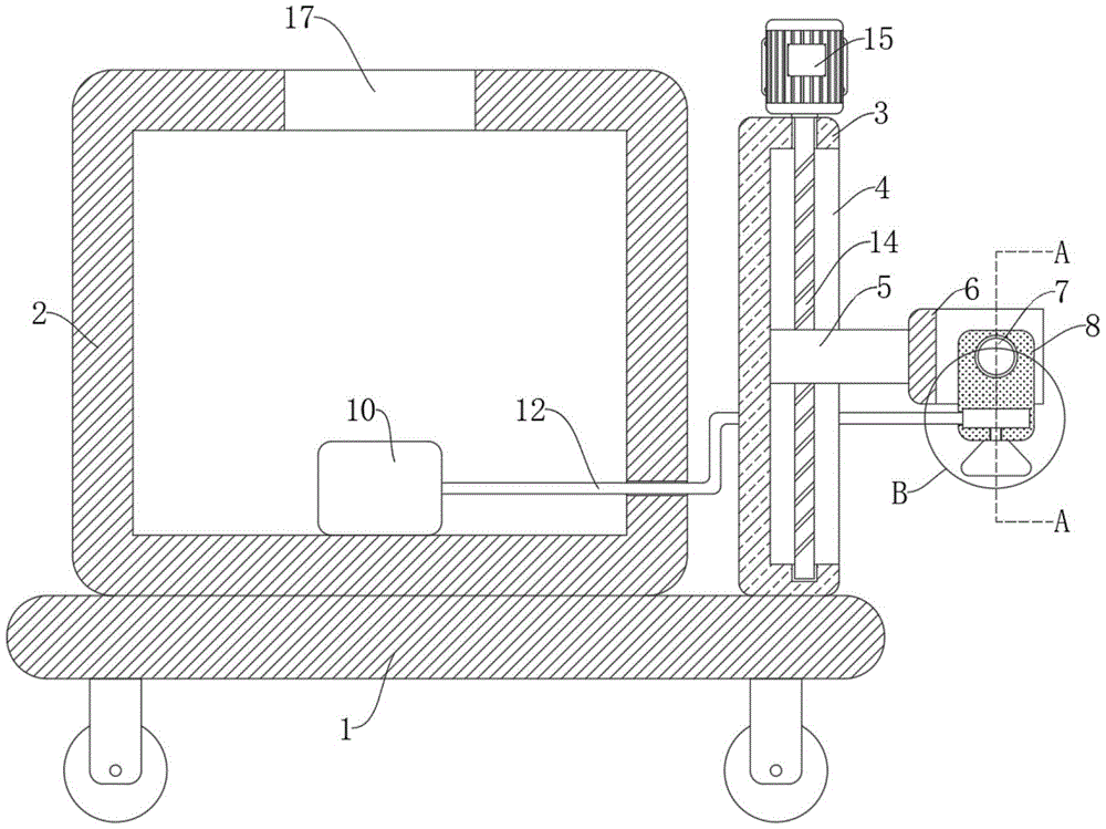
Fig. 1 is a schematic structural view of an energy-saving maintenance device for building construction provided by the utility model;
FIG. 2 is a schematic cross-sectional view of the structure along line A-A of FIG. 1;
fig. 3 is an enlarged schematic view of the structure at B in fig. 1.
In the figure: the device comprises a base 1, a water storage tank 2, an installation rod 3, a sliding groove 4, a sliding block 5, an installation frame 6, a rotating shaft 7, an installation seat 8, an atomizing nozzle 9, a water pump 10, a water inlet groove 11, a water inlet pipe 12, a water supply pipe 13, a screw rod 14, a motor 15, a servo motor 16 and a water inlet 17.
Detailed Description
The technical solutions in the embodiments of the present invention will be described clearly and completely with reference to the accompanying drawings in the embodiments of the present invention, and it is obvious that the described embodiments are only some embodiments of the present invention, not all embodiments.
In the description of the present invention, it is to be understood that the terms "upper", "lower", "front", "rear", "left", "right", "top", "bottom", "inner", "outer", and the like indicate orientations or positional relationships based on the orientations or positional relationships shown in the drawings, and are only for convenience of description and simplicity of description, and do not indicate or imply that the device or element being referred to must have a particular orientation, be constructed and operated in a particular orientation, and therefore, should not be construed as limiting the present invention.
Referring to fig. 1-3, an energy-saving maintenance device for building construction comprises a base 1, support columns symmetrically and fixedly connected with the lower end of the base 1, and the universal wheel is all installed to the support column lower extreme, be convenient for the removal of whole device, 1 upper end fixedly connected with storage water tank 2 of base, 1 upper end fixedly connected with installation pole 3 of base, spout 4 has been seted up to installation pole 3 lateral wall, 4 inner wall sliding connection of spout have slider 5, 5 lateral wall fixed connection mounting brackets 6 of slider, mounting bracket 6 is the U-shaped form, 6 inner wall rotations of mounting bracket are connected with pivot 7, 7 lateral wall fixedly connected with mount pads 8 of pivot, 8 lower extreme fixedly connected with of mount pad 9 a plurality of atomizer 9, it explains that atomizer 9 can spout the liquid atomization, for prior art, install the water supply mechanism who supplies water in a plurality of atomizer 9 on the storage water tank 2, water inlet 17 has been seted up to 2 upper ends of storage water tank.
The water supply mechanism includes water pump 10 of fixed connection bottom in storage water tank 2, has seted up intake chamber 11 in the mount pad 8, and intake chamber 11 communicates with water pump 10 through inlet tube 12, and intake chamber 11 communicates with a plurality of atomizer 9 through a plurality of delivery pipes 13.
Install actuating mechanism in the spout 4, actuating mechanism is including rotating the lead screw 14 of connection at the 4 inner walls of spout, 14 lateral walls of lead screw and 5 threaded connection of slider, and 3 upper end fixedly connected with motors 15 of installation pole, the 15 output of motor run through the installation pole 3 upper ends and with 14 fixed connection of lead screw, it needs to explain that 5 lateral walls of slider offset with 4 inner walls of spout for slider 5 can not produce the rotation.
The side wall of the mounting frame 6 is fixedly connected with a servo motor 16, and the output end of the servo motor 16 penetrates through the side wall of the mounting frame 6 and is fixedly connected with the rotating shaft 7.
In the utility model, water is firstly added into the water storage tank 2 through the water inlet 17, when spraying and maintaining the ground, the servo motor 16 is driven to rotate, the rotating shaft 7 is driven to rotate, the mounting seat 8 is further driven to rotate, the atomizer 9 is just under the rotation, then the water pump 10 is started, under the action of the water pump 10, the water in the water storage tank 2 is pumped into the water inlet tank 11 through the water inlet pipe 12, then the water in the water tank 11 enters the atomizer 9 through the water supply pipes 13, and then the water is atomized by the atomizer 9 and then sprayed out, so that the concrete ground is sprayed and maintained;
when needs spray the maintenance to the wall, rotate through drive servo motor 16, it rotates to drive pivot 7, and then drive mount pad 8 and rotate, it rotates to drive atomizer 9, adjust the angle of atomizer 9, rotate through driving motor 15, it rotates to drive lead screw 14, and then drive slider 5 at 4 inner walls of spout upwards or lapse, it upwards perhaps moves down to drive mounting bracket 6, it upwards perhaps moves down to drive mount pad 8, it upwards perhaps moves down to drive atomizer 9, highly adjust atomizer 9, be convenient for the not wall of co-altitude and angle to spray the maintenance.
The above, only be the concrete implementation of the preferred embodiment of the present invention, but the protection scope of the present invention is not limited thereto, and any person skilled in the art is in the technical scope of the present invention, according to the technical solution of the present invention and the utility model, the concept of which is equivalent to replace or change, should be covered within the protection scope of the present invention.