CN217513515U - Polishing equipment for machining spline shaft product - Google Patents
Polishing equipment for machining spline shaft product Download PDFInfo
- Publication number
- CN217513515U CN217513515U CN202222273025.1U CN202222273025U CN217513515U CN 217513515 U CN217513515 U CN 217513515U CN 202222273025 U CN202222273025 U CN 202222273025U CN 217513515 U CN217513515 U CN 217513515U
- Authority
- CN
- China
- Prior art keywords
- polishing
- fixedly arranged
- upside
- platform
- fixed
- Prior art date
- Legal status (The legal status is an assumption and is not a legal conclusion. Google has not performed a legal analysis and makes no representation as to the accuracy of the status listed.)
- Active
Links
Images




Landscapes
- Constituent Portions Of Griding Lathes, Driving, Sensing And Control (AREA)
Abstract
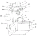
The utility model belongs to the technical field of the integral key shaft technique and specifically relates to a spline shaft product processing is with equipment of polishing, including the platform of polishing, the downside of the platform of polishing is fixed and is equipped with a plurality of supporting legs, the upside central point of the platform of polishing puts the fixed supporting seat that is equipped with, the upside of supporting seat is equipped with the integral key shaft, both ends all are equipped with clamping mechanism about the upside of the platform of polishing, the fixed L type support that is equipped with in upside rear end of the platform of polishing, the upside central point of L type support puts and is equipped with the cylinder, the axle head of cylinder is equipped with portable grinding machanism, this spline shaft product processing is with equipment of polishing, polish evenly, the rotary reciprocating type is polished, the quality of polishing promotes, dustless polishing.
Description
Technical Field
The utility model relates to a integral key shaft technical field especially relates to a spline shaft product processing is with equipment of polishing.
Background
The spline shaft is a mechanical transmission type, has the same functions as a flat key, a semicircular key and a wedge key and is used for transmitting mechanical torque, a longitudinal key groove is formed in the outer surface of the shaft, and a rotating part sleeved on the shaft is also provided with a corresponding key groove which can keep synchronous rotation with the shaft. While rotating, some can also slide longitudinally on the shaft, such as a gear shifting gear of a gearbox and the like.
When a spline shaft product is machined, the spline shaft product is usually required to be polished, when the spline shaft is polished, most of the spline shaft products are fixed in position and then polished, but the polishing condition is uneven in polishing the surface of the spline shaft, so that the polishing quality is influenced, and therefore, polishing equipment for machining the spline shaft product is provided.
SUMMERY OF THE UTILITY MODEL
The utility model aims at solving and having the integral key shaft product among the prior art and adding man-hour, need polish usually, when polishing the integral key shaft, most of them all carry out the position fixing with the integral key shaft, then polish, but this kind of condition of polishing is polished the surface of integral key shaft inhomogeneously to influence the shortcoming of the quality of polishing, and the spline shaft product processing of proposing is with equipment of polishing.
In order to achieve the above purpose, the utility model adopts the following technical scheme:
the grinding device for machining the spline shaft product comprises a grinding table, wherein a plurality of supporting legs are fixedly arranged on the lower side of the grinding table, a supporting seat is fixedly arranged at the center position of the upper side of the grinding table, a spline shaft is arranged on the upper side of the supporting seat, clamping mechanisms are arranged at the left end and the right end of the upper side of the grinding table, an L-shaped support is fixedly arranged at the rear end of the upper side of the grinding table, an air cylinder is arranged at the center position of the upper side of the L-shaped support, a connecting frame is fixedly arranged at the shaft end of the air cylinder and is in a U-shaped structure, a second motor is fixedly arranged on the left side of the connecting frame, a threaded rod is fixedly arranged at the shaft end of the second motor, the right end of the threaded rod is rotatably connected to the inner end of the right side of the connecting frame, a movable block is sleeved on the outer side of the threaded rod through threaded transmission, a third motor is fixedly arranged on the lower side of the movable block, a grinding head is fixedly arranged at the shaft end of the third motor, and a spraying mechanism is fixedly arranged on the left side of the motor III.
Preferably, the clamping mechanism includes: the grinding table comprises electric push rods, wherein the number of the electric push rods is two, the electric push rods are respectively arranged on the left side and the right side of the supporting seat and connected to the upper side of the grinding table, a clamping plate is fixedly arranged at the shaft end of each electric push rod, a rotating plate is arranged on the inner side of the clamping plate in a rotating mode, the left side and the right side of the rotating plate are both penetrated through the clamping plate and extend to the outside, a mounting plate is fixedly arranged on the right side of the clamping plate, a first motor is fixedly arranged on the upper side of the mounting plate, a driving gear is fixedly arranged at the shaft end of the first motor, a driven gear is arranged on one side of the driving gear in a meshing transmission mode, and the driven gear is fixedly connected to the right side of the rotating plate.
Preferably, the spraying mechanism comprises: the curb plate, the curb plate sets up in the left side of motor three, the fixed atomizer that is equipped with of downside of curb plate, the fixed corrugated hose that is equipped with of input of atomizer, the fixed feed water tank that is equipped with of one end of corrugated hose, the feed water tank sets up in the upside of L type support, the fixed aqueduct one that is equipped with in rear side of feed water tank, the fixed suction pump that is equipped with of one end of aqueduct, the fixed aqueduct two that is equipped with of input end of suction pump, the fixed collecting box that is equipped with in one end of aqueduct two, the upside of the platform of polishing is equipped with and runs through the mouth, it is the communicating structure setting with the collecting box to run through the mouth, it is equipped with a plurality of roller bearings to rotate the connection on the mouthful inside wall.
Preferably, the sliding connection is equipped with the filter screen on the inside wall of collecting box, the fixed cardboard that is equipped with in front side of filter screen, the cardboard buckle is connected in the front side of collecting box.
Preferably, the upper side of the supporting seat is respectively provided with a guide groove and a guide hole, and the guide groove and the guide hole are arranged in a communicated structure.
The utility model provides a pair of spline axle processing is with equipment of polishing, beneficial effect lies in: through setting up electric putter, splint, the rotor plate, motor one, the driving gear, driven gear, can provide a integral key shaft and press from both sides tight back and can carry out rotatory function, make the integral key shaft surface can rotate when polishing, thereby polish more comprehensively more evenly, improve the quality of polishing, through setting up the connection frame, motor two, the threaded rod, the movable block, motor three, the head of polishing, can provide a reciprocating type function of polishing of removing, through setting up the curb plate, the atomizer, the ripple hose, the supply tank, aqueduct one, the suction pump, aqueduct two, the collecting box, the filter screen, the cardboard, run through the mouth, can provide a dustless function of polishing, shower water can cyclic utilization simultaneously, this integral key shaft is grinding equipment for product processing, polish evenly, rotatory reciprocating type is polished, the quality of polishing promotes, dustless polishing.
Drawings
Fig. 1 is a schematic view of a front axial measurement structure of a polishing device for processing a spline shaft product provided by the present invention;
fig. 2 is a schematic view of a front cut axial structure of the polishing device for processing the spline shaft product provided by the utility model;
fig. 3 is a schematic side cut-away axial structure diagram of the polishing equipment for processing the spline shaft product provided by the utility model;
fig. 4 is a schematic side axial view of the polishing device for processing the spline shaft product provided by the present invention;
fig. 5 is a schematic structural diagram of a in fig. 4 of a polishing apparatus for machining a spline shaft product according to the present invention;
fig. 6 is the utility model provides a spline shaft product processing is with supporting seat structure sketch map of equipment of polishing.
In the figure: the grinding machine comprises a grinding table 1, supporting legs 2, a supporting seat 3, a spline shaft 4, a support frame 5L-shaped, an air cylinder 6, an electric push rod 7, a clamping plate 8, a rotating plate 9, a motor I10, a driving gear 11, a driven gear 31, a connecting frame 12, a motor II 13, a threaded rod 14, a movable block 15, a motor III 16, a grinding head 17, a side plate 18, an atomizing nozzle 19, a corrugated hose 30, a water supply tank 20, a water guide pipe I21, a water suction pump 22, a water guide pipe II 23, a water guide pipe 24 collecting tank 25, a filter screen 26, a clamping plate 27 rolling shaft, a guide groove 28 and a guide hole 29.
Detailed Description
The technical solutions in the embodiments of the present invention will be described clearly and completely with reference to the accompanying drawings in the embodiments of the present invention, and it is obvious that the described embodiments are only some embodiments of the present invention, not all embodiments.
It should be noted that the first motor 10, the second motor 13, and the third motor 16 are all micro motors, and the micro motors are motors with small volume and capacity, output power generally below several hundred watts, and special requirements for use, performance, and environmental conditions.
The micro motor is a motor with a diameter less than 160mm or rated power less than 750W, and is commonly used in a control system or a transmission mechanical load and used for realizing the functions of detecting, analyzing, operating, amplifying, executing or converting electromechanical signals or energy and the like.
The atomizing nozzle 19 sprays pressurized water flow into the air through the nozzle and scatters in a mist form.
Referring to fig. 1-6, a spline shaft product processing is with equipment of polishing, including polishing platform 1, the fixed a plurality of supporting legs 2 that are equipped with of downside of polishing platform 1, the fixed supporting seat 3 that is equipped with of upside central point of polishing platform 1 puts, and the upside of supporting seat 3 is equipped with integral key shaft 4, and both ends all are equipped with clamping mechanism about the upside of polishing platform 1, and the fixed L type support 5 that is equipped with in upside rear end of polishing platform 1, and the upside central point of L type support 5 puts and is equipped with cylinder 6.
In order to provide a rotatory function when pressing from both sides tight spline shaft 4, make its surface polish more evenly more comprehensively, improve the quality of polishing, set up clamping mechanism and include: the grinding machine comprises electric push rods 7, wherein the number of the electric push rods 7 is two, the electric push rods 7 are respectively arranged on the left side and the right side of a supporting seat 3 and connected to the upper side of a grinding table 1, a clamping plate 8 is fixedly arranged at the shaft end of each electric push rod 7, a rotating plate 9 is rotatably connected to the inner side of each clamping plate 8, the left side and the right side of each rotating plate 9 penetrate through the clamping plates 8 and extend to the outside, a mounting plate is fixedly arranged on the right side of each clamping plate 8, a first motor 10 is fixedly arranged on the upper side of the mounting plate, a driving gear 11 is fixedly arranged at the shaft end of the first motor 10, a driven gear 31 is arranged on one side of the driving gear 11 in a meshing transmission connection mode, and the driven gear 31 is fixedly connected to the right side of the rotating plate 9;
during the use, utilize electric putter 7 to promote splint 8, make the rotor plate 9 in the splint 8 inconsistent with the one end of integral key shaft 4, accomplish and press from both sides tightly, then utilize a motor 10 drive driving gear 11, transmission driven gear 31, driven gear 31 drives rotor plate 9 and orders about integral key shaft 4 and rotate to polish more comprehensively the surface of integral key shaft 4.
In order to facilitate displacement polishing and achieve a dust-free polishing effect, a connecting frame 12 is fixedly arranged at the shaft end of the air cylinder 6, the connecting frame 12 is arranged in a U-shaped structure, a second motor 13 is fixedly arranged on the left side of the connecting frame 12, a threaded rod 14 is fixedly arranged at the shaft end of the second motor 13, the right end of the threaded rod 14 is rotatably connected to the inner end of the right side of the connecting frame 12, a moving block 15 is sleeved on the outer side of the threaded rod 14 through thread transmission, a third motor 16 is fixedly arranged on the lower side of the moving block 15, a polishing head 17 is fixedly arranged at the shaft end of the third motor 16, and a spraying mechanism is fixedly arranged on the left side of the third motor 16;
when the polishing machine works, the air cylinder 6 pushes the connecting frame 12 to move to a proper position, then the second motor 13 on the left side of the connecting frame 12 drives the threaded rod 14 to drive the moving block 15, meanwhile, the third motor 16 drives the polishing head 17 to perform rotary polishing, and a dust-free polishing state is formed when the spraying mechanism is matched to perform polishing.
In order to provide a function of dustless cyclic spraying of polishing, it includes to have set up spraying mechanism: the grinding table comprises a side plate 18, the side plate 18 is arranged on the left side of a motor III 16, an atomizing nozzle 19 is fixedly arranged on the lower side of the side plate 18, a corrugated hose 30 is fixedly arranged at the input end of the atomizing nozzle 19, a water supply tank 20 is fixedly arranged at one end of the corrugated hose 30, the water supply tank 20 is arranged on the upper side of an L-shaped support 5, a water guide pipe I21 is fixedly arranged on the rear side of the water supply tank 20, a water suction pump 22 is fixedly arranged at one end of the water guide pipe I21, a water guide pipe II 23 is fixedly arranged at the input end of the water suction pump 22, a collecting box 24 is fixedly arranged at one end of the water guide pipe II 23, a through hole is formed in the upper side of the grinding table 1, the through hole and the collecting box 24 are arranged in a communicated structure, and a plurality of rolling shafts 27 are rotatably connected to the inner side wall of the through hole;
during operation, the atomizing nozzle 19 absorbs water in the water supply tank 20 through the corrugated hose 30 for atomizing and spraying, then the sprayed liquid falls on the grinding table 1 and flows into the collection tank 24 through the through hole, then circulating water collected by the collection tank 24 is injected into the water guide pipe 21 through the input end of the water suction pump 22 and flows into the water supply tank 20 through the water guide pipe II 23, and therefore the function of recycling spraying water is achieved.
In order to avoid the dust particles mixed in the spray water after polishing to follow the spray water for recycling, the filter screen 25 is arranged on the inner side wall of the collecting box 24 in a sliding connection mode, the clamping plate 26 is fixedly arranged on the front side of the filter screen 25, the clamping plate 26 is connected to the front side of the collecting box 24 in a buckling mode, the spray water after being used is filtered by the filter screen 25, the recycle spray water without impurities is used, and the filter screen 25 can be regularly drawn out from the collecting box 24 to be cleaned.
In order to avoid water accumulation on the upper side of the supporting seat 3, the upper side of the supporting seat 3 is respectively provided with a guide groove 28 and a guide hole 29, and the guide groove 28 and the guide hole 29 are arranged in a communicating structure.
The utility model discloses during the use, at first place integral key shaft 4 on supporting seat 3, then utilize clamping mechanism to carry on spacingly to integral key shaft 4, by cylinder 6 of 5 upsides of L type support with portable grinding machanism propelling movement to appointed position, then polish the operation.
In the description of the present invention, it should be noted that the terms "upper", "lower", "inner", "outer", "front end", "rear end", "both ends", "one end", "the other end" and the like indicate orientations or positional relationships based on the orientations or positional relationships shown in the drawings, and are only for convenience of description and simplification of description, but do not indicate or imply that the device or element to which the reference is made must have a specific orientation, be constructed in a specific orientation, and be operated, and thus, should not be construed as limiting the present invention. Furthermore, the terms "first" and "second" are used for descriptive purposes only and are not to be construed as indicating or implying relative importance.
In the description of the present invention, it is to be noted that, unless otherwise explicitly specified or limited, the terms "mounted," "disposed," "connected," and the like are to be construed broadly, and for example, "connected" may be either fixedly connected or detachably connected, or integrally connected; can be mechanically or electrically connected; they may be connected directly or indirectly through intervening media, or they may be interconnected between two elements. The specific meaning of the above terms in the present invention can be understood according to specific situations by those skilled in the art.
The above, only be the concrete implementation of the preferred embodiment of the present invention, but the protection scope of the present invention is not limited thereto, and any person skilled in the art is in the technical scope of the present invention, according to the technical solution of the present invention and the utility model, the concept of which is equivalent to replace or change, should be covered within the protection scope of the present invention.
Claims (5)
1. The utility model provides a spline shaft product processing is with equipment of polishing, includes platform (1) of polishing, the downside of platform (1) of polishing is fixed and is equipped with a plurality of supporting legs (2), its characterized in that, the upside central point of platform (1) of polishing puts fixedly and is equipped with supporting seat (3), the upside of supporting seat (3) is equipped with integral key shaft (4), both ends all are equipped with clamping mechanism about the upside of platform (1) of polishing, the upside rear end of platform (1) of polishing is fixed with L type support (5), the upside central point of L type support (5) puts and is equipped with cylinder (6), the axle head of cylinder (6) is fixed and is equipped with connection frame (12), connection frame (12) are the setting of U type structure, the left side of connection frame (12) is fixed and is equipped with motor two (13), the axle head of motor two (13) is fixed and is equipped with threaded rod (14), the right-hand member of threaded rod (14) rotates the right-hand member and connects the right side at connection frame (12) of inner, the outer side of the threaded rod (14) is provided with a moving block (15) in a sleeved mode through threaded transmission, a motor III (16) is fixedly arranged on the lower side of the moving block (15), a polishing head (17) is fixedly arranged at the shaft end of the motor III (16), and a spraying mechanism is fixedly arranged on the left side of the motor III (16).
2. The grinding apparatus for machining a spline shaft product according to claim 1, wherein the clamping mechanism comprises: electric putter (7), electric putter (7) quantity is two, sets up respectively in supporting seat (3) the left and right sides and connects the upside at platform (1) of polishing, the fixed splint (8) that are equipped with of axle head of electric putter (7), splint (8) inboard rotation is connected and is equipped with rotor plate (9), the left and right sides of rotor plate (9) all runs through in splint (8) and extends to outside, the fixed mounting panel that is equipped with in right side of splint (8), the fixed motor (10) that are equipped with of upside of mounting panel, the fixed driving gear (11) that are equipped with of axle head of motor (10), one side meshing transmission of driving gear (11) is connected and is equipped with driven gear (31), driven gear (31) fixed connection is on the right side of rotor plate (9).
3. The grinding apparatus for machining a spline shaft product according to claim 1, wherein the spraying mechanism includes: a side plate (18), wherein the side plate (18) is arranged at the left side of the motor III (16), an atomizing nozzle (19) is fixedly arranged on the lower side of the side plate (18), a corrugated hose (30) is fixedly arranged at the input end of the atomizing nozzle (19), one end of the corrugated hose (30) is fixedly provided with a water supply tank (20), the water supply tank (20) is arranged on the upper side of the L-shaped bracket (5), a first water guide pipe (21) is fixedly arranged at the rear side of the water supply tank (20), a water suction pump (22) is fixedly arranged at one end of the first water guide pipe (21), a second water guide pipe (23) is fixedly arranged at the input end of the water suction pump (22), a collection box (24) is fixedly arranged at one end of the second water guide pipe (23), the upside of platform (1) of polishing is equipped with and runs through the mouth, it is the communicating structure setting with collecting box (24) to run through the mouth, it is equipped with a plurality of roller bearings (27) to run through to rotate the connection on the mouthful inside wall.
4. The grinding equipment for processing the spline shaft products as claimed in claim 3, wherein a filter screen (25) is slidably connected to the inner side wall of the collection box (24), a clamping plate (26) is fixedly arranged on the front side of the filter screen (25), and the clamping plate (26) is connected to the front side of the collection box (24) in a clamping mode.
5. The grinding device for machining the spline shaft product as claimed in claim 1, wherein the upper side of the supporting seat (3) is respectively provided with a guide groove (28) and a guide hole (29), and the guide groove (28) and the guide hole (29) are arranged in a communicated structure.
Priority Applications (1)
| Application Number | Priority Date | Filing Date | Title |
|---|---|---|---|
| CN202222273025.1U CN217513515U (en) | 2022-08-29 | 2022-08-29 | Polishing equipment for machining spline shaft product |
Applications Claiming Priority (1)
| Application Number | Priority Date | Filing Date | Title |
|---|---|---|---|
| CN202222273025.1U CN217513515U (en) | 2022-08-29 | 2022-08-29 | Polishing equipment for machining spline shaft product |
Publications (1)
| Publication Number | Publication Date |
|---|---|
| CN217513515U true CN217513515U (en) | 2022-09-30 |
Family
ID=83394604
Family Applications (1)
| Application Number | Title | Priority Date | Filing Date |
|---|---|---|---|
| CN202222273025.1U Active CN217513515U (en) | 2022-08-29 | 2022-08-29 | Polishing equipment for machining spline shaft product |
Country Status (1)
| Country | Link |
|---|---|
| CN (1) | CN217513515U (en) |
Cited By (1)
| Publication number | Priority date | Publication date | Assignee | Title |
|---|---|---|---|---|
| CN121199777A (en) * | 2025-11-18 | 2025-12-26 | 赣州元聚新材料有限公司 | A smart surface treatment equipment for cemented carbide bars |
-
2022
- 2022-08-29 CN CN202222273025.1U patent/CN217513515U/en active Active
Cited By (1)
| Publication number | Priority date | Publication date | Assignee | Title |
|---|---|---|---|---|
| CN121199777A (en) * | 2025-11-18 | 2025-12-26 | 赣州元聚新材料有限公司 | A smart surface treatment equipment for cemented carbide bars |
Similar Documents
| Publication | Publication Date | Title |
|---|---|---|
| CN207592805U (en) | A kind of center lathe metal debris separates and collects device with waste liquid | |
| CN107599410A (en) | The 3D printer scrap collecting tank cleaning plant being convenient to clean | |
| CN209831253U (en) | A hand-held miniature lacquerware polishing device | |
| CN214440315U (en) | Powder conveying and cleaning device for powder spraying room | |
| CN110303379A (en) | A kind of component of machine processing scrap clearing and retrieving device | |
| CN213783228U (en) | Self-cleaning device for waterborne solar cell panel | |
| CN111701921B (en) | Automatic cleaning equipment for elevator car | |
| CN217491442U (en) | Gluing device for plate production | |
| CN208894681U (en) | The reciprocal clean run device of platen surface | |
| CN117385716A (en) | A kind of marking equipment for road construction | |
| CN215355240U (en) | Mechanical equipment processing work piece belt cleaning device | |
| CN216323744U (en) | Cleaning device convenient for wastewater recovery and used for deep groove ball bearing processing | |
| CN207373704U (en) | The 3D printer scrap collecting tank cleaning plant being convenient to clean | |
| CN217997938U (en) | Track cleaning device | |
| CN220970127U (en) | Steel ball cleaning device | |
| CN222493523U (en) | Polishing equipment convenient to clearance | |
| CN222404899U (en) | High-precision casting polishing table | |
| CN222842621U (en) | Cleaning device for cold punching grinding tool of punching machine | |
| CN220330926U (en) | Metal rack equipment of polishing convenient to garbage collection | |
| CN215547321U (en) | Surface grinding and polishing machine for processing galvanized air pipe | |
| CN223669310U (en) | Horizontal dull polish machine convenient to fully grind | |
| CN220126982U (en) | Single-station rotary spraying cleaning machine | |
| CN217699176U (en) | Reaction kettle device for producing surfactant | |
| CN213559160U (en) | Cleaning device for band steel processing | |
| CN221183959U (en) | Coating film belt cleaning device |
Legal Events
| Date | Code | Title | Description |
|---|---|---|---|
| GR01 | Patent grant | ||
| GR01 | Patent grant |