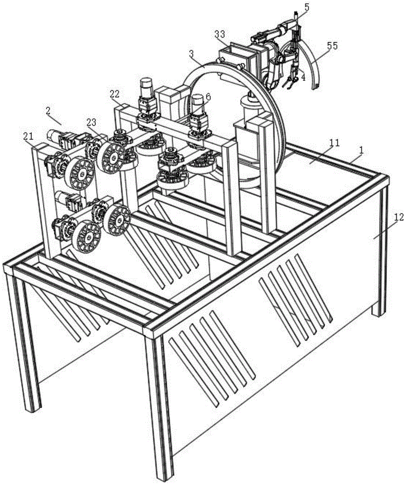
Pipe body welding table with positioning function
Technical Field
The utility model relates to a body welding technology field specifically is a body welding bench with locate function.
Background
When a pipe body is machined, the pipe body is usually welded, wherein when the pipe body welding positioning tool disclosed in the application number of CN201721154322.7 is applied to pipe body welding, the positioning tool for welding a bent pipe body on a straight pipe body comprises a base, a rotating shaft, an installation block, screws, pressing blocks, nuts, supporting blocks, cushion blocks, lifting rods and fastening screws, wherein the installation block is rotatably connected to the base through the rotating shaft, the two screws are welded on two sides of the installation block, the pressing blocks are sleeved on the screws, the nuts are in threaded connection with the screws, the supporting blocks are vertically welded on the installation block, the lifting rods are movably inserted on the supporting blocks, the lifting rods are parallel to the installation block, the cushion blocks are fixedly connected to the top ends of the lifting rods, the fastening screws are in threaded connection with the supporting blocks, and one end of the lifting rods is abutted to the lifting rods; two briquetting pressure contacts in the both ends of the straight tube body, and on the curved tube body was arranged in to the bottom port of curved tube body, top port welded with the straight tube body, this kind of welding position frock when welding the pipe fitting, though can realize convenient welding to the pipe fitting, nevertheless need manual regulation welding angle and go up unloading to the pipe fitting in welding process, welded efficiency can't be guaranteed, and the practicality remains to improve to a certain extent.
SUMMERY OF THE UTILITY MODEL
An object of the utility model is to provide a body welding bench with locate function to solve the problem that above-mentioned background art provided.
In order to achieve the above object, the utility model provides a following technical scheme: the utility model provides a body welding bench with locate function, includes the rack, direction conveying mechanism is installed to the top one end of rack, one side of direction conveying mechanism is equipped with the circle type motion of installing in the rack top, circle type motion rotates one side and installs welding cutting mechanism, the cabinet body is installed to the other end of rack, unloading mechanism on the centre gripping is installed at the top of the cabinet body, the CCD camera that is used for the location to detect is all installed to unloading mechanism on direction conveying mechanism, welding cutting mechanism and the centre gripping.
As an optimal scheme of the utility model: the guide conveying mechanism comprises a first support frame and a second support frame which are respectively installed on two cross beams at the top of the rack, driving mechanisms are installed on one side of the first support frame and the bottom of the second support frame and comprise longitudinal supporting plates, two transverse supporting plates are fixedly installed at the bottoms of the longitudinal supporting plates, pipeline guide wheels are installed at two ends of each transverse supporting plate, and two pipeline guide wheels are connected with a first driving motor installed at the top of each longitudinal supporting plate in a transmission mode.
As a preferred scheme of the utility model: the driving mechanism installed on the first support frame is vertically opposite to the driving mechanism installed on the second support frame, and a CCD camera is installed on one side of the second support frame.
As an optimal scheme of the utility model: the circle type motion mechanism is including installing two track support frames on one of them crossbeam in rack top, two track support frame's top one side fixed mounting has the circle type track, outer guide way and interior guide way have been seted up respectively to orbital outer lane of circle type and inner circle, one side of track support frame is equipped with the frame type frame, two sets of track leading wheels are installed to one side of frame type frame, are located two track leading wheels and the outer guide way sliding connection at top, are located two track leading wheels and the interior guide way sliding connection of bottom, the internally mounted of frame type frame has second driving motor, second driving motor's output shaft runs through frame type frame bottom and installs the gear, the gear is connected with the ring gear meshing of track support frame one side-mounting.
As an optimal scheme of the utility model: the welding and cutting mechanism comprises a first mechanical arm fixedly mounted at the top of the frame-shaped frame, a laser welding head and a laser cutting head are mounted at one end of the first mechanical arm, and a CCD camera is further mounted at the end of the first mechanical arm.
As an optimal scheme of the utility model: the last unloading mechanism of centre gripping includes the second manipulator of fixed mounting in cabinet body top, the fixed block is installed to the one end of second manipulator, the cylinder is installed at the top of fixed block, articulated seat is installed to the flexible end of cylinder, articulated seat rotates through two connecting rods of connecting and is connected with the arm lock, two the fluting that the one end of arm lock was equipped with through pin and fixed block rotates and is connected.
As an optimal scheme of the utility model: the internal portion of cabinet has the PLC controller, first driving motor, second driving motor, first manipulator and second manipulator all pass through PLC controller and external power supply electric connection, CCD camera and PLC controller electric connection.
Compared with the prior art, the beneficial effects of the utility model are that: two actuating mechanism through direction conveying mechanism setting can carry out the automation to the body and carry, the last unloading mechanism of centre gripping of setting can carry out the centre gripping to pipe fittings such as return bend or body, and fix a position through the CCD camera, make the pipe fitting can accurately place body weld part, the circle type motion cooperation welding cutting mechanism of setting can carry out 360 degrees automatic weld fast with pipe fitting and body, improve pipe fitting welded efficiency, when needs cut the body of fixed length, utilize the laser cutting head to accomplish the cutting fast, improve the practicality of this body welding bench.
Drawings
Fig. 1 is a schematic view of the structure of the present invention;
FIG. 2 is a schematic view of the present invention;
fig. 3 is a schematic structural view of the driving mechanism of the present invention;
FIG. 4 is a schematic structural view of the ring-shaped motion mechanism of the present invention;
FIG. 5 is a schematic structural view of the ring-shaped moving mechanism of the present invention;
fig. 6 is a schematic structural view of the feeding and discharging mechanism for clamping of the present invention.
In the figure: 1. a rack; 11. a cabinet body; 12. a baffle plate; 2. a guide conveying mechanism; 21. a first support frame; 22. a second support frame; 23. a drive mechanism; 231. a longitudinal bracing plate; 232. a transverse supporting plate; 233. a pipeline guide wheel; 234. a first drive motor; 3. a loop-type motion mechanism; 31. a rail support frame; 32. a loop-shaped track; 321. an outer guide groove; 322. an inner guide groove; 323. a ring gear; 33. a frame-shaped frame; 34. a rail guide wheel; 35. a second drive motor; 4. a welding and cutting mechanism; 41. a first manipulator; 42. a laser welding head; 43. a laser cutting head; 5. a material loading and unloading mechanism is clamped; 51. a second manipulator; 52. a cylinder; 53. a hinged seat; 54. a connecting rod; 55. clamping arms; 6. a CCD camera.
Detailed Description
The technical solutions in the embodiments of the present invention will be described clearly and completely with reference to the accompanying drawings in the embodiments of the present invention, and it is obvious that the described embodiments are only some embodiments of the present invention, not all embodiments. Based on the embodiments in the present invention, all other embodiments obtained by a person skilled in the art without creative work belong to the protection scope of the present invention.
Referring to fig. 1-6, the present invention provides a technical solution: a pipe welding table with a positioning function comprises a table frame 1, wherein a guide conveying mechanism 2 is installed at one end of the top of the table frame 1, a ring-shaped moving mechanism 3 installed at the top of the table frame 1 is arranged on one side of the guide conveying mechanism 2, a welding and cutting mechanism 4 is rotatably installed on one side of the ring-shaped moving mechanism 3, a cabinet body 11 is installed at the other end of the table frame 1, a clamping and feeding and discharging mechanism 5 is installed at the top of the cabinet body 11, and baffles 12 are installed on two sides of the table frame 1;
the CCD camera 6 that is used for the location to detect is all installed to direction conveying mechanism 2, welding cutting mechanism 4 and the last unloading mechanism 5 of centre gripping, and cabinet body 11 internally mounted has the PLC controller, and first driving motor 234, second driving motor 35, first manipulator 41 and second manipulator 51 are all through PLC controller and external power supply electric connection, CCD camera 6 and PLC controller electric connection.
In this embodiment: the guide conveying mechanism 2 comprises a first support frame 21 and a second support frame 22 which are respectively arranged on two cross beams at the top of the rack 1, a driving mechanism 23 is arranged on one side of the first support frame 21 and the bottom of the second support frame 22, the driving mechanism 23 comprises a longitudinal support plate 231, two transverse support plates 232 are fixedly arranged at the bottoms of the longitudinal support plates 231, pipeline guide wheels 233 are arranged at two ends of each transverse support plate 232, and the two pipeline guide wheels 233 are in transmission connection with a first driving motor 234 arranged at the top of each longitudinal support plate 231.
Specifically, when welding the pipe body and the pipe fitting (the elbow pipe and the pipe table), one end of the pipe body with an opening (the size of the opening is matched with the size of the elbow pipe or the pipe table) can be inserted between the pipeline guide wheels 233 of the two driving mechanisms 23, the first driving motor 234 is controlled by the PLC controller to drive the corresponding pipeline guide wheels 233 to rotate, and when the pipeline guide wheels 233 rotate, the pipe body can be automatically conveyed;
the driving mechanism 23 arranged on the first support frame 21 is vertically opposite to the driving mechanism 23 arranged on the second support frame 22, and the CCD camera 6 is arranged on one side of the second support frame 22;
specifically, two actuating mechanism 23 set up perpendicularly relatively for the body can pass two actuating mechanism 23's pipeline leading wheel 233 and rolling contact, realizes carrying, and the CCD camera 6 that sets up simultaneously can carry out the record and the opening position on body surface to the length that the body was carried, realizes fixing a position the length position that the body was carried.
In this embodiment: the last unloading mechanism 5 of centre gripping includes second manipulator 51 of fixed mounting on the cabinet body 11 top, and the fixed block is installed to the one end of second manipulator 51, and cylinder 52 is installed at the top of fixed block, and articulated seat 53 is installed to the flexible end of cylinder 52, and articulated seat 53 rotates through two connecting rods 54 of connecting and is connected with arm lock 55, and the fluting that pin and fixed block were equipped with is passed through to the one end of two arm lock 55 rotates and is connected, and CCD camera 6 is installed in the other end outside of two arm lock 55.
Specifically, when the pipe body is carried ring type motion 3 department, go forward action through PLC controller control second manipulator 51, control cylinder 52 drives articulated seat 53 downstream simultaneously, articulated seat 53 cooperation connecting rod 54 of downstream makes two arm lock 55 rotate and open, utilize second manipulator 51 to drive arm lock 55 and control cylinder 52 withdrawal, realize carrying out the centre gripping to the pipe fitting, then place the opening part of pipe body with the pipe fitting, can utilize CCD camera 6 to fix a position when placing.
In this embodiment: the ring-shaped movement mechanism 3 comprises two track support frames 31 arranged on one of the cross beams at the top of the rack 1, a ring-shaped track 32 is fixedly arranged on one side of the top ends of the two track support frames 31, an outer guide groove 321 and an inner guide groove 322 are respectively formed in the outer ring and the inner ring of the ring-shaped track 32, a frame 33 is arranged on one side of the track support frames 31, two sets of track guide wheels 34 are arranged on one side of the frame 33, the two track guide wheels 34 positioned at the top are slidably connected with the outer guide groove 321, the two track guide wheels 34 positioned at the bottom are slidably connected with the inner guide groove 322, a second driving motor 35 is arranged inside the frame 33, an output shaft of the second driving motor 35 penetrates through the bottom of the frame 33 and is provided with a gear, and the gear is meshed with a gear ring 323 arranged on one side of the track support frames 31.
In this embodiment: after the pipe fitting is placed at the opening of the pipe body, the PLC controller controls the second driving motor 35 to drive the gear to rotate, the rotating gear can be matched with the gear ring 323 to drive the frame 33 to move on the ring-shaped track 32, and the arranged track guide wheel 34 is in rolling fit with the outer guide groove 321 and the inner guide groove 322 to ensure that the frame 33 can stably move on the ring-shaped track 32 by 0-360 degrees.
In this embodiment: the welding and cutting mechanism 4 comprises a first manipulator 41 fixedly mounted on the top of the frame 33, a laser welding head 42 and a laser cutting head 43 are mounted at one end of the first manipulator 41, and a CCD camera 6 is further mounted at the end of the first manipulator 41.
Specifically, when the frame 33 moves, the PLC controller controls the first manipulator 41 to drive the laser welding head 42 to align with the contact position between the pipe and the pipe body, so as to rapidly weld the pipe;
when the fixed length cutting is carried out to the body of welding the pipe fitting when needs, the direction conveying mechanism 2 carries certain length back to the body, utilizes the last unloading mechanism 5 of centre gripping to carry out the centre gripping to the one end of body, then through the motion of frame 33, drives laser cutting head 43 through PLC controller control second manipulator 51 and aims at the body outer wall, realizes the fly-cutting to the body, then carries out the unloading through last unloading mechanism 5 of centre gripping to the body after the cutting can.
Although the present invention has been described in detail with reference to the foregoing embodiments, it will be apparent to those skilled in the art that modifications and equivalents may be made without departing from the spirit and scope of the invention.