CN217504293U - Heat energy recovery system of hollow blade dryer - Google Patents
Heat energy recovery system of hollow blade dryer Download PDFInfo
- Publication number
- CN217504293U CN217504293U CN202221428786.3U CN202221428786U CN217504293U CN 217504293 U CN217504293 U CN 217504293U CN 202221428786 U CN202221428786 U CN 202221428786U CN 217504293 U CN217504293 U CN 217504293U
- Authority
- CN
- China
- Prior art keywords
- box
- heat exchange
- water storage
- fixedly connected
- filter
- Prior art date
- Legal status (The legal status is an assumption and is not a legal conclusion. Google has not performed a legal analysis and makes no representation as to the accuracy of the status listed.)
- Expired - Fee Related
Links
Images


Landscapes
- Separating Particles In Gases By Inertia (AREA)
Abstract
本实用新型公开了一种空心桨叶干燥机的热能回收系统,包括底板,所述底板的顶部固定连接有换热箱与蓄水箱,所述蓄水箱位于换热箱的右侧,所述换热箱的左侧固定连接有与其内部相连通的进气管,所述换热箱的顶部固定安装有抽液泵,所述抽液泵的底端贯穿并延伸至换热箱的内部,所述抽液泵的底端固定连接有螺旋换热管。该实用新型,通过位于蓄水箱内部的输气管对废气进行二次换热,提高热回收的效率,通过驱动电机带动滤板转动,在不影响对气体过滤的同时可以对滤板进行敲击,使得附着在滤板上的灰尘颗粒脱落至收集盒内部被收集,避免滤板堵塞影响过滤。
The utility model discloses a heat energy recovery system of a hollow blade dryer, comprising a bottom plate, a heat exchange box and a water storage tank are fixedly connected to the top of the bottom plate, and the water storage tank is located on the right side of the heat exchange box, so the The left side of the heat exchange box is fixedly connected with an air intake pipe that communicates with its interior, the top of the heat exchange box is fixedly installed with a liquid pumping pump, and the bottom end of the liquid pumping pump penetrates and extends to the interior of the heat exchange box, The bottom end of the liquid suction pump is fixedly connected with a spiral heat exchange tube. In the utility model, the exhaust gas is subjected to secondary heat exchange through the gas transmission pipe located inside the water storage tank to improve the efficiency of heat recovery, and the filter plate is driven to rotate by the driving motor, so that the filter plate can be knocked without affecting the gas filtration. , so that the dust particles attached to the filter plate fall off to the inside of the collection box to be collected, so as to avoid the blockage of the filter plate and affect the filtration.
Description
技术领域technical field
本实用新型涉及一种空心桨叶干燥机的热能回收系统。The utility model relates to a heat energy recovery system of a hollow paddle dryer.
背景技术Background technique
空心桨叶干燥机是一种以热传导为主的卧式搅拌型干燥机,因内部空心的搅拌叶片形似于船桨,固称之为空心桨叶干燥机,桨叶干燥机国外已经开发多年,这种机型在国外已开发出双轴和四轴两种结构、多个规格的系列产品,由于该设备干燥时所需热量是依靠热传导间接加热,因此干燥过程只需少量的气体以带走湿分,这就极大地减少了被气体带走的这部分热量的损耗,提高了热量的利用率。The hollow paddle dryer is a horizontal stirring dryer mainly based on heat conduction. Because the hollow stirring blade inside is similar to the paddle, it is called a hollow paddle dryer. The paddle dryer has been developed abroad for many years. This type of model has been developed abroad with two-axis and four-axis structures and a series of products of multiple specifications. Since the heat required for drying of this equipment is indirectly heated by heat conduction, only a small amount of gas is needed in the drying process. Moisture, which greatly reduces the loss of this part of the heat taken away by the gas, and improves the utilization rate of heat.
目前现有的空心桨叶干燥机排出的废气具有较高的热量,很大一部分会直接排放,这样不仅浪费了很大的一部分能源,而且会导致车间工作环境温度越来越高,同时还会污染大气环境。At present, the exhaust gas discharged from the existing hollow blade dryer has high heat, and a large part will be directly discharged, which not only wastes a large part of energy, but also leads to higher and higher working environment temperature in the workshop. pollute the atmosphere.
实用新型内容Utility model content
针对现有技术中存在的相关问题,本实用新型的目的在于提供一种空心桨叶干燥机的热能回收系统。In view of the related problems existing in the prior art, the purpose of the present invention is to provide a heat energy recovery system for a hollow paddle dryer.
为解决上述问题,本实用新型采用如下的技术方案。In order to solve the above problems, the present invention adopts the following technical solutions.
一种空心桨叶干燥机的热能回收系统,包括底板,所述底板的顶部固定连接有换热箱与蓄水箱,所述蓄水箱位于换热箱的右侧,所述换热箱的左侧固定连接有与其内部相连通的进气管,所述换热箱的顶部固定安装有抽液泵,所述抽液泵的底端贯穿并延伸至换热箱的内部,所述抽液泵的底端固定连接有螺旋换热管,所述螺旋换热管的另一端与蓄水箱的内部相连通,所述换热箱的内顶壁上固定连接有隔板,所述隔板套设在螺旋换热管上,所述蓄水箱的顶部固定连接有与其内部相连通的进水管,所述进水管上安装有电磁阀,所述换热箱的右侧固定连接有与其内部相连通的输气管,所述底板的顶部固定连接有过滤箱,所述输气管的另一端贯穿蓄水箱并延伸至过滤箱的内部,所述蓄水箱的内壁上固定安装有液位传感器,所述蓄水箱的内部集成有单片机,所述液位传感器与电磁阀均与单片机信号连接,所述过滤箱的内壁上开设有弧形槽,所述过滤箱的顶部固定安装有驱动电机,所述驱动电机的输出轴贯穿过滤箱并转动连接在弧形槽的内底壁上,所述驱动电机的输出轴上固定连接有均匀分布的滤板,所述滤板与弧形槽的内壁贴合,所述过滤箱的右侧插接有收集盒,所述收集盒的底部与过滤箱的内底壁滑动连接,所述过滤箱的内壁上固定安装有两个电动推杆,所述电动推杆的输出端上固定连接有敲块,所述过滤箱的右侧开设有与其内部相连通的排气槽。A heat energy recovery system for a hollow blade dryer, comprising a bottom plate, a heat exchange box and a water storage tank are fixedly connected to the top of the bottom plate, the water storage tank is located on the right side of the heat exchange box, and the The left side is fixedly connected with an air intake pipe that communicates with its interior, the top of the heat exchange box is fixedly installed with a pump, the bottom end of the pump runs through and extends to the interior of the heat exchange box, the pump The bottom end of the heat exchange tube is fixedly connected with a spiral heat exchange tube, and the other end of the spiral heat exchange tube is communicated with the interior of the water storage tank. Set on the spiral heat exchange tube, the top of the water storage tank is fixedly connected with a water inlet pipe that communicates with its interior, a solenoid valve is installed on the water inlet pipe, and the right side of the heat exchange box is fixedly connected to its interior. The top of the bottom plate is fixedly connected with a filter box, the other end of the gas pipeline penetrates the water storage tank and extends to the interior of the filter box, and a liquid level sensor is fixedly installed on the inner wall of the water storage tank. The inside of the water storage tank is integrated with a single-chip microcomputer, the liquid level sensor and the solenoid valve are both connected with the single-chip microcomputer signal, the inner wall of the filter box is provided with an arc-shaped groove, and the top of the filter box is fixedly installed with a drive motor. The output shaft of the drive motor runs through the filter box and is rotatably connected to the inner bottom wall of the arc-shaped groove. The output shaft of the drive motor is fixedly connected with evenly distributed filter plates, which are connected to the inner wall of the arc-shaped groove. Fittingly, a collection box is inserted on the right side of the filter box, the bottom of the collection box is slidably connected to the inner bottom wall of the filter box, and two electric push rods are fixedly installed on the inner wall of the filter box, and the A knock block is fixedly connected to the output end of the electric push rod, and an exhaust groove communicated with the inside of the filter box is provided on the right side of the filter box.
作为上述技术方案的进一步描述:所述蓄水箱的正面固定安装有控制面板,所述抽液泵、驱动电机与电动推杆均与控制面板电性连接。As a further description of the above technical solution, a control panel is fixedly installed on the front of the water storage tank, and the liquid pump, the drive motor and the electric push rod are all electrically connected to the control panel.
作为上述技术方案的进一步描述:所述过滤箱的右侧可拆卸式连接有防尘板,所述防尘板位于排气槽的右侧。As a further description of the above technical solution, a dust-proof plate is detachably connected to the right side of the filter box, and the dust-proof plate is located on the right side of the exhaust slot.
作为上述技术方案的进一步描述:所述收集盒的右侧固定连接有拉手,所述拉手上开设有均匀分布的防滑纹。As a further description of the above technical solution: the right side of the collection box is fixedly connected with a handle, and the handle is provided with evenly distributed anti-skid lines.
作为上述技术方案的进一步描述:所述蓄水箱的正面固定安装有提示器,所述提示器与单片机信号连接。As a further description of the above technical solution: a prompter is fixedly installed on the front of the water storage tank, and the prompter is signal-connected to the single-chip microcomputer.
作为上述技术方案的进一步描述:所述底板的顶部设置有保温套,所述保温套固定连接在输气管上。As a further description of the above technical solution: the top of the bottom plate is provided with a thermal insulation jacket, and the thermal insulation jacket is fixedly connected to the gas transmission pipe.
相比于现有技术,本实用新型的优点在于:Compared with the prior art, the advantages of the present utility model are:
本实用新型通过螺旋换热管增大与废气的换热面积,延长冷却水在换热箱内部的时间,从而可以提高换热效率,通过位于蓄水箱内部的输气管对废气进行二次换热,提高热回收的效率,通过驱动电机带动滤板转动,在不影响对气体过滤的同时可以对滤板进行敲击,使得附着在滤板上的灰尘颗粒脱落至收集盒内部被收集,避免滤板堵塞影响过滤。The utility model increases the heat exchange area with the exhaust gas through the spiral heat exchange pipe, prolongs the time of the cooling water in the heat exchange box, thereby improving the heat exchange efficiency, and the exhaust gas is exchanged for the second time through the gas transmission pipe located in the water storage tank. Heat, improve the efficiency of heat recovery, drive the filter plate to rotate through the drive motor, the filter plate can be knocked without affecting the gas filtration, so that the dust particles attached to the filter plate fall off to the inside of the collection box to be collected, avoiding Clogging of the filter plate affects filtration.
附图说明Description of drawings
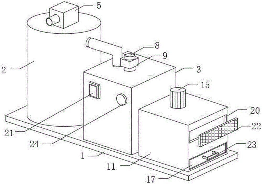
图1为本实用新型的立体结构示意图;Fig. 1 is the three-dimensional structure schematic diagram of the present utility model;
图2为本实用新型的正视剖面结构示意图;Fig. 2 is the front view sectional structure schematic diagram of the utility model;
图3为本实用新型的过滤箱俯视剖面结构示意图;Fig. 3 is the top view sectional structure schematic diagram of the filter box of the utility model;
图4为本实用新型的原理示意图。FIG. 4 is a schematic diagram of the principle of the present invention.
图中标号说明:Description of the labels in the figure:
1、底板;2、换热箱;3、蓄水箱;4、进气管;5、抽液泵;6、螺旋换热管;7、隔板;8、进水管;9、电磁阀;10、输气管;11、过滤箱;12、液位传感器;13、单片机;14、弧形槽;15、驱动电机;16、滤板;17、收集盒;18、电动推杆;19、敲块;20、排气槽;21、控制面板;22、防尘板;23、拉手;24、提示器;25、保温套。1. Bottom plate; 2. Heat exchange tank; 3. Water storage tank; 4. Air intake pipe; 5. Liquid pump; 6. Spiral heat exchange pipe; 7. Baffle plate; 8. Water inlet pipe; 9. Solenoid valve; 10 , gas pipeline; 11, filter box; 12, liquid level sensor; 13, microcontroller; 14, arc groove; 15, drive motor; 16, filter plate; 17, collection box; 18, electric push rod; 19, knock block ; 20, exhaust slot; 21, control panel; 22, dust plate; 23, handle; 24, prompter; 25, insulation cover.
具体实施方式Detailed ways
下面将结合本实用新型实施例中的附图,对本实用新型实施例中的技术方案进行清楚、完整地描述;The technical solutions in the embodiments of the present utility model will be described clearly and completely below in conjunction with the accompanying drawings in the embodiments of the present utility model;
请参阅图1~4,本实用新型中,一种空心桨叶干燥机的热能回收系统,包括底板1,底板1的顶部固定连接有换热箱2与蓄水箱3,蓄水箱3位于换热箱2的右侧,换热箱2的左侧固定连接有与其内部相连通的进气管4,换热箱2的顶部固定安装有抽液泵5,抽液泵5的底端贯穿并延伸至换热箱2的内部,抽液泵5的底端固定连接有螺旋换热管6,螺旋换热管6的另一端与蓄水箱3的内部相连通,换热箱2的内顶壁上固定连接有隔板7,隔板7套设在螺旋换热管6上,蓄水箱3的顶部固定连接有与其内部相连通的进水管8,进水管8上安装有电磁阀9,换热箱2的右侧固定连接有与其内部相连通的输气管10,底板1的顶部固定连接有过滤箱11,输气管10的另一端贯穿蓄水箱3并延伸至过滤箱11的内部,蓄水箱3的内壁上固定安装有液位传感器12,蓄水箱3的内部集成有单片机13,液位传感器12与电磁阀9均与单片机13信号连接,过滤箱11的内壁上开设有弧形槽14,过滤箱11的顶部固定安装有驱动电机15,驱动电机15的输出轴贯穿过滤箱11并转动连接在弧形槽14的内底壁上,驱动电机15的输出轴上固定连接有均匀分布的滤板16,滤板16与弧形槽14的内壁贴合,过滤箱11的右侧插接有收集盒17,收集盒17的底部与过滤箱11的内底壁滑动连接,过滤箱11的内壁上固定安装有两个电动推杆18,电动推杆18的输出端上固定连接有敲块19,过滤箱11的右侧开设有与其内部相连通的排气槽20。Please refer to FIGS. 1 to 4. In the present invention, a heat energy recovery system of a hollow blade dryer includes a
本实用新型中,当需要对空心桨叶干燥机排除的气体的进行热回收时,使用人员将干燥机的排气管与换热箱2的进气管4相连通,随后使用人员将进水管8与外部外接水管连接,控制抽液泵5通电工作,抽液泵5通电后产生吸力将蓄水箱3内部的冷却水抽入螺旋换热管6内部,废气进入换热箱2内部后受到隔板7的限制开始向下移动,废气与螺旋换热管6接触并与其进行换热,从而使得废气的温度下降,冷却水的温度上升,使用人员可将抽液泵5排除的热水进行收集使用,废气经过隔板7后向上运动并进入输气管10内部,随后通过输气管10进入蓄水箱3内部进行二次换热,使得废气中的热量被冷却水吸收,随后废气被排入过滤箱11内部,随着抽液泵5的持续工作蓄水箱3内部液面下移,液位传感器12将信号传递给单片机13,单片机13接收后控制电磁阀9通电打开,外接水管内部的冷却水进入蓄水箱3内部,废气进入过滤箱11内部后处于弧形槽14内部,由于滤板16与弧形槽14的内壁贴合气体向右侧移动的过程会穿过滤板16,滤板16则会将气体中附着的灰尘颗粒进行阻隔吸附,随后气体通过排气槽20排出,使用人员控制驱动电机15通电工作,驱动电机15通电后带动滤板16发生转动,从而使得附着有灰尘的滤板16移动至收集盒17的顶部,随后使用人员控制电动推杆18通电工作,电动推杆18通电后带动与其固定连接的敲块19对滤板16进行敲击,使得附着在滤板16上的灰尘颗粒脱落至收集盒17内部被收集,解决了以往空心桨叶干燥机的热能回收系统实用性不佳的问题。In the present invention, when it is necessary to perform heat recovery of the gas exhausted by the hollow blade dryer, the user connects the exhaust pipe of the dryer with the air inlet pipe 4 of the
请参阅图1,其中:蓄水箱3的正面固定安装有控制面板21,抽液泵5、驱动电机15与电动推杆18均与控制面板21电性连接。Please refer to FIG. 1 , wherein a
本实用新型中,控制面板21的设置可以使得使用人员更加简单快捷的操控此装置,以此减少人员的投入与所需要操作的步骤,从而提高此装置的实用性。In the present invention, the setting of the
请参阅图1与2,其中:过滤箱11的右侧可拆卸式连接有防尘板22,防尘板22位于排气槽20的右侧。Please refer to FIGS. 1 and 2 , wherein: the right side of the
本实用新型中,防尘板22的设置可以对经过排气槽20的气体起到过滤作用,使得气体可以通过排气槽20,但气体中附着的灰尘颗粒则会被防尘板22阻隔。In the present invention, the
请参阅图1~3,其中:收集盒17的右侧固定连接有拉手23,拉手23上开设有均匀分布的防滑纹。Please refer to FIGS. 1 to 3 , wherein: the right side of the
本实用新型中,当使用人员需要拉动收集盒17时,拉手23可以为其提供一个很好的着力点,防滑纹则可以防止使用人员发生手滑。In the present invention, when the user needs to pull the
请参阅图1与4,其中:蓄水箱3的正面固定安装有提示器24,提示器24与单片机13信号连接。Please refer to FIGS. 1 and 4 , wherein: a
本实用新型中,当液位传感器12将信号传递给单片机13时,单片机13会同时控制提示器24通电工作,提示器24通电后发出提示声对使用人员进行提示。In the present invention, when the
请参阅图1与2,其中:底板1的顶部设置有保温套25,保温套25固定连接在输气管10上。Please refer to FIGS. 1 and 2 , wherein: the top of the
本实用新型中,保温套25的设置可以避免输气管10与外部空气接触进行换热,从而减少热量的流失,提高热量回收的效率。In the present invention, the
工作原理:当需要对空心桨叶干燥机排除的气体的进行热回收时,使用人员将干燥机的排气管与换热箱2的进气管4相连通,随后使用人员将进水管8与外部外接水管连接,控制抽液泵5通电工作,抽液泵5通电后产生吸力将蓄水箱3内部的冷却水抽入螺旋换热管6内部,废气进入换热箱2内部后受到隔板7的限制开始向下移动,废气与螺旋换热管6接触并与其进行换热,从而使得废气的温度下降,冷却水的温度上升,使用人员可将抽液泵5排除的热水进行收集使用,废气经过隔板7后向上运动并进入输气管10内部,随后通过输气管10进入蓄水箱3内部进行二次换热,使得废气中的热量被冷却水吸收,随后废气被排入过滤箱11内部,随着抽液泵5的持续工作蓄水箱3内部液面下移,液位传感器12将信号传递给单片机13,单片机13接收后控制电磁阀9通电打开,外接水管内部的冷却水进入蓄水箱3内部,废气进入过滤箱11内部后处于弧形槽14内部,由于滤板16与弧形槽14的内壁贴合气体向右侧移动的过程会穿过滤板16,滤板16则会将气体中附着的灰尘颗粒进行阻隔吸附,随后气体通过排气槽20排出,使用人员控制驱动电机15通电工作,驱动电机15通电后带动滤板16发生转动,从而使得附着有灰尘的滤板16移动至收集盒17的顶部,随后使用人员控制电动推杆18通电工作,电动推杆18通电后带动与其固定连接的敲块19对滤板16进行敲击,使得附着在滤板16上的灰尘颗粒脱落至收集盒17内部被收集,解决了以往空心桨叶干燥机的热能回收系统实用性不佳的问题。Working principle: When the heat recovery of the gas exhausted by the hollow blade dryer is required, the user connects the exhaust pipe of the dryer with the air inlet pipe 4 of the
以上所述,仅为本实用新型较佳的具体实施方式;但本实用新型的保护范围并不局限于此。任何熟悉本技术领域的技术人员在本实用新型揭露的技术范围内,根据本实用新型的技术方案及其改进构思加以等同替换或改变,都应涵盖在本实用新型的保护范围内。The above descriptions are only preferred specific embodiments of the present invention; however, the protection scope of the present invention is not limited thereto. Any person skilled in the art who is familiar with the technical scope disclosed by the present utility model, according to the technical solution of the present utility model and its improvement concept, equivalently replaces or changes, should be covered within the protection scope of the present utility model.
Claims (6)
Priority Applications (1)
| Application Number | Priority Date | Filing Date | Title |
|---|---|---|---|
| CN202221428786.3U CN217504293U (en) | 2022-06-09 | 2022-06-09 | Heat energy recovery system of hollow blade dryer |
Applications Claiming Priority (1)
| Application Number | Priority Date | Filing Date | Title |
|---|---|---|---|
| CN202221428786.3U CN217504293U (en) | 2022-06-09 | 2022-06-09 | Heat energy recovery system of hollow blade dryer |
Publications (1)
| Publication Number | Publication Date |
|---|---|
| CN217504293U true CN217504293U (en) | 2022-09-27 |
Family
ID=83359517
Family Applications (1)
| Application Number | Title | Priority Date | Filing Date |
|---|---|---|---|
| CN202221428786.3U Expired - Fee Related CN217504293U (en) | 2022-06-09 | 2022-06-09 | Heat energy recovery system of hollow blade dryer |
Country Status (1)
| Country | Link |
|---|---|
| CN (1) | CN217504293U (en) |
-
2022
- 2022-06-09 CN CN202221428786.3U patent/CN217504293U/en not_active Expired - Fee Related
Similar Documents
| Publication | Publication Date | Title |
|---|---|---|
| CN212810964U (en) | Distribution control cabinet convenient to overhaul | |
| CN103307663B (en) | Fixed temperature and humidity heat pump fresh air | |
| CN112082415A (en) | Flue gas waste heat recovery and heat exchange device and heat exchange method based on industrial energy conservation | |
| CN111765794A (en) | A laboratory waste gas heat recovery device | |
| CN211782377U (en) | A drying device for emulsion explosives | |
| CN222011964U (en) | Boiler flue waste heat recovery device | |
| CN219551250U (en) | Water cooling device for thermal power plant | |
| CN215073627U (en) | PLC control cabinet of sewage pumping station | |
| CN209074434U (en) | A kind of energy saving dust suction wind pump being convenient to clean | |
| CN115625040A (en) | A combined honeycomb ceramic multi-tube dedusting device for coal-fired flue gas treatment | |
| CN114130136B (en) | An energy-saving flue gas treatment control system | |
| CN218451983U (en) | Energy-concerving and environment-protective type circulation dust removal electrical equipment | |
| CN217226629U (en) | Bottle blowing device of horizontal rotary bottle blowing machine | |
| CN217817956U (en) | Energy-saving dryer for new material forming | |
| CN221905957U (en) | Oil filtering device for thermal oil furnace | |
| CN221155839U (en) | Air energy production line for drying high-moisture heat-insulating material | |
| CN211575956U (en) | Waste heat evaporator convenient for ash removal | |
| CN208968297U (en) | A kind of rotary kiln dedusting cooling device | |
| CN218179127U (en) | Building energy-saving air interchanger | |
| CN222012346U (en) | Solar environment-friendly air heater | |
| CN221923665U (en) | Condensate water recycling device for heat exchange station | |
| CN212029879U (en) | Zero-gas-loss steam heating structure of air treatment system | |
| CN222417514U (en) | A natural gas boiler condensate recovery device | |
| CN214635117U (en) | Efficient dust remover equipment | |
| CN215892419U (en) | Combustion system optimizing device |
Legal Events
| Date | Code | Title | Description |
|---|---|---|---|
| GR01 | Patent grant | ||
| GR01 | Patent grant | ||
| CF01 | Termination of patent right due to non-payment of annual fee |
Granted publication date: 20220927 |
|
| CF01 | Termination of patent right due to non-payment of annual fee |