CN217473330U - A kind of mixer for o-chlorophenylglycine preparation - Google Patents
A kind of mixer for o-chlorophenylglycine preparation Download PDFInfo
- Publication number
- CN217473330U CN217473330U CN202221240597.3U CN202221240597U CN217473330U CN 217473330 U CN217473330 U CN 217473330U CN 202221240597 U CN202221240597 U CN 202221240597U CN 217473330 U CN217473330 U CN 217473330U
- Authority
- CN
- China
- Prior art keywords
- rod
- fixedly connected
- stirring
- chlorophenylglycine
- collection box
- Prior art date
- Legal status (The legal status is an assumption and is not a legal conclusion. Google has not performed a legal analysis and makes no representation as to the accuracy of the status listed.)
- Expired - Fee Related
Links
Images



Landscapes
- Mixers Of The Rotary Stirring Type (AREA)
Abstract
本实用新型涉及邻氯苯甘氨酸制备技术领域,提出了一种邻氯苯甘氨酸制备用混料机,包括工作台,工作台的上表面设置有搅拌机构,工作台的下表面设置有取料机构,搅拌机构包括空心杆、支撑架和电机,工作台的上表面转动连接有空心杆,空心杆的圆周面固定连接有搅拌桶和第一蜗轮,支撑架的侧表面转动连接有第一转杆,第一转杆的圆周面固定连接有偏心杆和第二蜗轮,支撑架的内上表面滑动连接有移动杆,移动杆的下表面固定连接有固定杆,固定杆的圆周面固定连接有搅拌杆,通过上述技术方案,可以带动搅拌桶转动并通过搅拌杆进行搅拌操作,并且可以带动搅拌杆进行往复移动来对搅拌桶内部不同高度的原料进行搅拌。

The utility model relates to the technical field of preparation of o-chlorophenylglycine, and provides a mixer for the preparation of o-chlorophenylglycine. , the stirring mechanism includes a hollow rod, a support frame and a motor. The upper surface of the worktable is rotatably connected with a hollow rod, the circumferential surface of the hollow rod is fixedly connected with a stirring bucket and a first worm gear, and the side surface of the support frame is rotatably connected with a first rotating rod , the circumferential surface of the first rotating rod is fixedly connected with an eccentric rod and a second worm wheel, the inner upper surface of the support frame is slidably connected with a moving rod, the lower surface of the moving rod is fixedly connected with a fixed rod, and the circumferential surface of the fixed rod is fixedly connected with a stirring rod Through the above technical solution, the stirring barrel can be driven to rotate and the stirring rod can be used for stirring operation, and the stirring rod can be driven to reciprocate to stir the raw materials of different heights inside the stirring barrel.
Description
技术领域technical field
本实用新型涉及邻氯苯甘氨酸制备技术领域,具体的,涉及一种邻氯苯甘氨酸制备用混料机。The utility model relates to the technical field of preparation of o-chlorophenylglycine, in particular to a mixer for the preparation of o-chlorophenylglycine.
背景技术Background technique
邻氯苯甘氨酸是一种白色或者类白色结晶性粉末,它的主要作用是制作品的中间体,可以改善身体出现的一些疾病。o-Chlorophenylglycine is a white or off-white crystalline powder. Its main function is as an intermediate in the production of products, which can improve some diseases in the body.
但是目前的邻氯苯甘氨酸制备用混料机在进行使用过程中,搅拌杆的位置为固定式的,不能调节高度来方便上层的原料快速进行混合,并且搅拌桶的内壁容易附着原料导致无法混合,从而造成混料产物成型率低,以及不方便将混合后的物料进行收集和移动的问题。However, during the use of the current mixer for o-chlorophenylglycine preparation, the position of the stirring rod is fixed, and the height cannot be adjusted to facilitate the rapid mixing of the raw materials in the upper layer, and the inner wall of the stirring barrel is easy to adhere to the raw materials and cannot be mixed. , resulting in the low molding rate of the mixed product and the inconvenience of collecting and moving the mixed material.
实用新型内容Utility model content
本实用新型提出一种邻氯苯甘氨酸制备用混料机,解决了不方便对搅拌桶上层物料进行混合和的搅拌桶内壁原料不方便清理的问题。The utility model proposes a mixer for the preparation of o-chlorophenylglycine, which solves the problem of inconvenient cleaning of the raw materials on the inner wall of the stirring barrel, which is inconvenient to mix and mix the materials on the upper layer of the stirring barrel.
本实用新型的技术方案如下:一种邻氯苯甘氨酸制备用混料机,包括工作台,所述工作台的上表面设置有搅拌机构,所述工作台的下表面设置有取料机构,所述搅拌机构包括空心杆、支撑架和电机,所述工作台的上表面转动连接有空心杆,所述空心杆的圆周面固定连接有搅拌桶和第一蜗轮,所述支撑架的侧表面转动连接有第一转杆,所述第一转杆的圆周面固定连接有偏心杆和第二蜗轮,所述支撑架的内上表面滑动连接有移动杆,所述移动杆的下表面固定连接有固定杆,所述固定杆的圆周面固定连接有搅拌杆,所述搅拌杆的一端固定连接有刮板,所述工作台的上表面固定连接有电机,所述电机的输出端固定连接有蜗杆,电机带动蜗杆进行转动,蜗杆和第一蜗轮发生啮合,使得第一蜗轮带动空心杆和搅拌桶发生转动,搅拌桶转动的同时通过搅拌杆进行搅拌,并通过刮板对其圆周面的原料进行清理,通过蜗杆和第二蜗轮啮合,使得第一转杆带动偏心杆转动,偏心杆转动带动压块上升,压块带动移动杆在支撑架的内部限位滑动,移动杆再带动固定杆上升,固定杆带动搅拌杆和刮板进行往复移动,使得不同高度的原料均可以进行搅拌。The technical scheme of the utility model is as follows: a mixer for the preparation of o-chlorophenylglycine, comprising a workbench, the upper surface of the workbench is provided with a stirring mechanism, and the lower surface of the workbench is provided with a material reclaiming mechanism, so The stirring mechanism includes a hollow rod, a support frame and a motor, a hollow rod is rotatably connected to the upper surface of the worktable, a stirring barrel and a first worm gear are fixedly connected to the circumferential surface of the hollow rod, and the side surface of the support frame rotates A first rotating rod is connected, the circumferential surface of the first rotating rod is fixedly connected with an eccentric rod and a second worm wheel, the inner upper surface of the support frame is slidably connected with a moving rod, and the lower surface of the moving rod is fixedly connected with a A fixed rod, a stirring rod is fixedly connected to the circumferential surface of the fixed rod, a scraper is fixedly connected to one end of the stirring rod, a motor is fixedly connected to the upper surface of the worktable, and a worm is fixedly connected to the output end of the motor , the motor drives the worm to rotate, and the worm and the first worm gear mesh, so that the first worm gear drives the hollow rod and the stirring barrel to rotate, and the stirring barrel rotates while stirring by the stirring rod. Cleaning, through the meshing of the worm and the second worm wheel, the first rotating rod drives the eccentric rod to rotate, the eccentric rod rotates to drive the pressure block to rise, the pressure block drives the moving rod to slide within the limit of the support frame, and the moving rod drives the fixed rod to rise, The fixed rod drives the stirring rod and the scraper to move back and forth, so that the raw materials of different heights can be stirred.
作为本实用新型进一步的方案:所述第一蜗轮和第二蜗轮均和蜗杆相互啮合,方便带动搅拌桶转动的同时再带动偏心杆进行运动,所述搅拌桶的上表面设置有进料口,方便进料操作。As a further solution of the present invention: the first worm gear and the second worm gear are meshed with the worm, which is convenient to drive the mixing barrel to rotate and then drive the eccentric rod to move, and the upper surface of the mixing barrel is provided with a feeding port, Convenient feeding operation.
作为本实用新型进一步的方案:所述支撑架的形状设置为L型,且支撑架的另一端和搅拌桶的上表面滑动连接,方便搅拌桶的上表面对支撑架进行支撑并且不妨碍搅拌桶进转动。As a further solution of the present invention: the shape of the support frame is set to be L-shaped, and the other end of the support frame is slidably connected to the upper surface of the mixing barrel, which is convenient for the upper surface of the mixing barrel to support the support frame and does not hinder the mixing barrel into rotation.
作为本实用新型进一步的方案:所述移动杆的另一端固定连接有压块,所述压块的下表面和偏心杆的圆周面相贴合,方便偏心杆转动的同时推动压块,压块推动移动杆进行运动。As a further solution of the present utility model: the other end of the moving rod is fixedly connected with a pressure block, and the lower surface of the pressure block is in contact with the circumferential surface of the eccentric rod, which facilitates the rotation of the eccentric rod and pushes the pressure block, and the pressure block pushes the pressure block. Move the rod to exercise.
作为本实用新型进一步的方案:所述刮板的形状和搅拌桶的内圆周面相贴合,方便对搅拌桶内壁的原料进行刮取查找,所述空心杆和进料口的内部均设置有阀门,方便控制排料出料。As a further solution of the present utility model: the shape of the scraper and the inner circumferential surface of the mixing barrel fit together, which is convenient for scraping and searching the raw materials on the inner wall of the mixing barrel, and valves are provided inside the hollow rod and the feeding port. , it is convenient to control the discharge and discharge.
作为本实用新型进一步的方案:所述取料机构包括限位架、限位板、收集盒和输送轴,所述工作台的下表面固定连接有限位架,所述限位架的上表面固定连接有限位板,所述限位架的上表面滑动连接有收集盒,所述限位架的内部转动连接有输送轴,搅拌完成后打开空心杆中的阀门即可将原料排入至收集盒中,收集完成后,拉动把手将收集盒通过输送轴排出,当需要再放置收集盒时,通过限位板和限位架定位,将收集盒定位放置在空心杆的正下方进行收集。As a further solution of the present invention: the reclaiming mechanism includes a limit frame, a limit plate, a collection box and a conveying shaft, the lower surface of the worktable is fixedly connected to the limit frame, and the upper surface of the limit frame is fixed Connect the limit plate, the upper surface of the limit frame is slidably connected with a collection box, and the interior of the limit frame is rotatably connected with a conveying shaft. After the stirring is completed, open the valve in the hollow rod to discharge the raw materials into the collection box After the collection is completed, pull the handle to discharge the collection box through the conveying shaft. When the collection box needs to be placed again, it is positioned by the limit plate and the limit frame, and the collection box is positioned and placed directly under the hollow rod for collection.
作为本实用新型进一步的方案:所述限位架的一端设置为倾斜型,方便收集盒滑下,两块所述限位板之间的距离和收集盒的宽度相匹配,方便对收集盒进行定位。As a further solution of the present invention, one end of the limit frame is set to be inclined, which is convenient for the collection box to slide down, and the distance between the two limit plates matches the width of the collection box, which is convenient for the collection box. position.
作为本实用新型进一步的方案:所述收集盒的前面固定连接有把手,方便拉动收集盒,所述收集盒的位置位于空心杆的正下方,方便进行收料。As a further solution of the present invention, a handle is fixedly connected to the front of the collection box, which is convenient for pulling the collection box, and the position of the collection box is located just below the hollow rod, which is convenient for collecting materials.
本实用新型的工作原理及有益效果为:The working principle and beneficial effects of the present utility model are as follows:
本实用新型中:通过设置有搅拌机构和取料机构,当使用该搅拌桶时,将原料放置在搅拌桶的内部,打开电机带动蜗杆进行转动,蜗杆和第一蜗轮发生啮合,使得第一蜗轮带动空心杆和搅拌桶发生转动,搅拌桶转动的同时通过搅拌杆进行搅拌,并通过刮板对其圆周面的原料进行清理,通过蜗杆和第二蜗轮啮合,使得第一转杆带动偏心杆转动,偏心杆转动带动压块上升,压块带动移动杆在支撑架的内部限位滑动,移动杆再带动固定杆上升,固定杆带动搅拌杆和刮板进行往复移动,使得不同高度的原料均可以进行搅拌,搅拌完成后打开空心杆中的阀门即可将原料排入至收集盒中,收集完成后,拉动把手将收集盒通过输送轴排出,当需要再放置收集盒时,通过限位板和限位架定位,将收集盒定位放置在空心杆的正下方进行收集,使用方便操作简单,可以带动搅拌桶转动并通过搅拌杆进行搅拌操作,并且可以带动搅拌杆进行往复移动来对搅拌桶内部不同高度的原料进行搅拌,还可以对搅拌桶内壁的原料进行刮取,以及方便将收集盒定位放置来收集混合后的原料。In the utility model: by being provided with a stirring mechanism and a material reclaiming mechanism, when the stirring barrel is used, the raw materials are placed inside the stirring barrel, the motor is turned on to drive the worm to rotate, and the worm and the first worm gear are engaged, so that the first worm gear is engaged. Drive the hollow rod and the mixing barrel to rotate, the mixing barrel rotates while stirring through the stirring rod, and the scraper cleans the raw materials on its circumferential surface, and the worm is meshed with the second worm wheel, so that the first rotating rod drives the eccentric rod to rotate. , the rotation of the eccentric rod drives the pressure block to rise, the pressure block drives the moving rod to slide in the inner limit of the support frame, the moving rod drives the fixed rod to rise, and the fixed rod drives the stirring rod and the scraper to move back and forth, so that materials of different heights can be After stirring, open the valve in the hollow rod to discharge the raw materials into the collection box. After the collection is completed, pull the handle to discharge the collection box through the conveying shaft. When the collection box needs to be placed again, pass the limit plate and The limit frame is positioned, and the collection box is positioned directly under the hollow rod for collection. It is easy to use and simple to operate. It can drive the stirring barrel to rotate and perform stirring operations through the stirring rod, and can drive the stirring rod to reciprocate to clean the inside of the stirring barrel. The raw materials of different heights can be stirred, and the raw materials on the inner wall of the mixing barrel can be scraped, and the collection box can be conveniently positioned to collect the mixed raw materials.
附图说明Description of drawings
下面结合附图和具体实施方式对本实用新型作进一步详细的说明。The present utility model will be described in further detail below with reference to the accompanying drawings and specific embodiments.
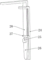
图1为本实用新型的整体结构示意图;Fig. 1 is the overall structure schematic diagram of the present utility model;
图2为本实用新型的搅拌机构的局部结构示意图;Fig. 2 is the partial structural representation of the stirring mechanism of the utility model;
图3为本实用新型的搅拌机构的另一视角的局部结构示意图;Fig. 3 is the partial structure schematic diagram of another angle of view of the stirring mechanism of the present invention;
图4为本实用新型的支撑杆的结构示意图;Fig. 4 is the structural representation of the support rod of the present invention;
图5为本实用新型的取料机构的结构示意图。FIG. 5 is a schematic structural diagram of the reclaiming mechanism of the present invention.
图中:1、工作台;2、搅拌机构;3、取料机构;21、空心杆;22、搅拌桶;23、第一蜗轮;24、支撑架;25、第一转杆;26、偏心杆;27、压块;28、移动杆;29、固定杆;210、搅拌杆;211、刮板;212、第二蜗轮;213、电机;214、蜗杆;215、进料口;31、限位架;32、限位板;33、收集盒;34、输送轴。In the figure: 1. Workbench; 2. Stirring mechanism; 3. Material reclaiming mechanism; 21. Hollow rod; 22. Mixing barrel; 23. First worm gear; 24. Support frame; Rod; 27, pressing block; 28, moving rod; 29, fixed rod; 210, stirring rod; 211, scraper; 212, second worm gear; 213, motor; 214, worm; 215, feeding port; 31, limit position frame; 32, limit plate; 33, collection box; 34, conveying shaft.
具体实施方式Detailed ways
下面将结合本实用新型实施例,对本实用新型实施例中的技术方案进行清楚、完整地描述,显然,所描述的实施例仅仅是本实用新型一部分实施例,而不是全部的实施例。基于本实用新型中的实施例,本领域普通技术人员在没有作出创造性劳动前提下所获得的所有其他实施例,都涉及本实用新型保护的范围。The technical solutions in the embodiments of the present utility model will be clearly and completely described below with reference to the embodiments of the present utility model. Obviously, the described embodiments are only a part of the embodiments of the present utility model, rather than all the embodiments. Based on the embodiments of the present invention, all other embodiments obtained by those of ordinary skill in the art without creative work, all relate to the protection scope of the present invention.
实施例1Example 1
如图1~图5所示:一种邻氯苯甘氨酸制备用混料机,包括工作台1,工作台1的上表面设置有搅拌机构2,工作台1的下表面设置有取料机构3,搅拌机构2包括空心杆21、支撑架24和电机213,工作台1的上表面转动连接有空心杆21,空心杆21的圆周面固定连接有搅拌桶22和第一蜗轮23,支撑架24的侧表面转动连接有第一转杆25,第一转杆25的圆周面固定连接有偏心杆26和第二蜗轮212,支撑架24的内上表面滑动连接有移动杆28,移动杆28的下表面固定连接有固定杆29,固定杆29的圆周面固定连接有搅拌杆210,搅拌杆210的一端固定连接有刮板211,工作台1的上表面固定连接有电机213,电机213的输出端固定连接有蜗杆214,电机213带动蜗杆214进行转动,蜗杆214和第一蜗轮23发生啮合,使得第一蜗轮23带动空心杆21和搅拌桶22发生转动,搅拌桶22转动的同时通过搅拌杆210进行搅拌,并通过刮板211对其圆周面的原料进行清理,通过蜗杆214和第二蜗轮212啮合,使得第一转杆25带动偏心杆26转动,偏心杆26转动带动压块27上升,压块27带动移动杆28在支撑架24的内部限位滑动,移动杆28再带动固定杆29上升,固定杆29带动搅拌杆210和刮板211进行往复移动,使得不同高度的原料均可以进行搅拌。As shown in Figures 1 to 5: a mixer for the preparation of o-chlorophenylglycine, comprising a workbench 1, the upper surface of the workbench 1 is provided with a
作为本实用新型进一步的方案:第一蜗轮23和第二蜗轮212均和蜗杆214相互啮合,方便带动搅拌桶22转动的同时再带动偏心杆26进行运动,搅拌桶22的上表面设置有进料口215,方便进料操作。As a further scheme of the present invention: the
作为本实用新型进一步的方案:支撑架24的形状设置为L型,且支撑架24的另一端和搅拌桶22的上表面滑动连接,方便搅拌桶22的上表面对支撑架24进行支撑并且不妨碍搅拌桶22进转动。As a further solution of the present invention: the shape of the
作为本实用新型进一步的方案:移动杆28的另一端固定连接有压块27,压块27的下表面和偏心杆26的圆周面相贴合,方便偏心杆26转动的同时推动压块27,压块27推动移动杆28进行运动。As a further solution of the present utility model: the other end of the moving
作为本实用新型进一步的方案:刮板211的形状和搅拌桶22的内圆周面相贴合,方便对搅拌桶22内壁的原料进行刮取查找,空心杆21和进料口215的内部均设置有阀门,方便控制排料出料。As a further scheme of the present invention, the shape of the
作为本实用新型进一步的方案:取料机构3包括限位架31、限位板32、收集盒33和输送轴34,工作台1的下表面固定连接有限位架31,限位架31的上表面固定连接有限位板32,限位架31的上表面滑动连接有收集盒33,限位架31的内部转动连接有输送轴34,搅拌完成后打开空心杆21中的阀门即可将原料排入至收集盒33中,收集完成后,拉动把手将收集盒33通过输送轴34排出,当需要再放置收集盒33时,通过限位板32和限位架31定位,将收集盒33定位放置在空心杆21的正下方进行收集。As a further scheme of the present invention: the reclaiming
作为本实用新型进一步的方案:限位架31的一端设置为倾斜型,方便收集盒33滑下,两块限位板32之间的距离和收集盒33的宽度相匹配,方便对收集盒33进行定位。As a further solution of the present invention: one end of the
作为本实用新型进一步的方案:收集盒33的前面固定连接有把手,方便拉动收集盒33,收集盒33的位置位于空心杆21的正下方,方便进行收料。As a further solution of the present invention, a handle is fixedly connected to the front of the
工作原理:当使用该搅拌桶22时,将原料放置在搅拌桶22的内部,打开电机213带动蜗杆214进行转动,蜗杆214和第一蜗轮23发生啮合,使得第一蜗轮23带动空心杆21和搅拌桶22发生转动,搅拌桶22转动的同时通过搅拌杆210进行搅拌,并通过刮板211对其圆周面的原料进行清理,通过蜗杆214和第二蜗轮212啮合,使得第一转杆25带动偏心杆26转动,偏心杆26转动带动压块27上升,压块27带动移动杆28在支撑架24的内部限位滑动,移动杆28再带动固定杆29上升,固定杆29带动搅拌杆210和刮板211进行往复移动,使得不同高度的原料均可以进行搅拌,搅拌完成后打开空心杆21中的阀门即可将原料排入至收集盒33中,收集完成后,拉动把手将收集盒33通过输送轴34排出,当需要再放置收集盒33时,通过限位板32和限位架31定位,将收集盒33定位放置在空心杆21的正下方进行收集,使用方便操作简单,可以带动搅拌桶22转动并通过搅拌杆210进行搅拌操作,并且可以带动搅拌杆210进行往复移动来对搅拌桶22内部不同高度的原料进行搅拌,还可以对搅拌桶22内壁的原料进行刮取,以及方便将收集盒33定位放置来收集混合后的原料。Working principle: when using the mixing
以上仅为本实用新型的较佳实施例而已,并不用以限制本实用新型,凡在本实用新型的精神和原则之内,所作的任何修改、等同替换、改进等,均应包含在本实用新型的保护范围之内。The above are only preferred embodiments of the present invention and are not intended to limit the present invention. Any modifications, equivalent replacements, improvements, etc. made within the spirit and principles of the present invention shall be included in the present invention. within the scope of the new protection.
Claims (8)
Priority Applications (1)
| Application Number | Priority Date | Filing Date | Title |
|---|---|---|---|
| CN202221240597.3U CN217473330U (en) | 2022-05-23 | 2022-05-23 | A kind of mixer for o-chlorophenylglycine preparation |
Applications Claiming Priority (1)
| Application Number | Priority Date | Filing Date | Title |
|---|---|---|---|
| CN202221240597.3U CN217473330U (en) | 2022-05-23 | 2022-05-23 | A kind of mixer for o-chlorophenylglycine preparation |
Publications (1)
| Publication Number | Publication Date |
|---|---|
| CN217473330U true CN217473330U (en) | 2022-09-23 |
Family
ID=83310957
Family Applications (1)
| Application Number | Title | Priority Date | Filing Date |
|---|---|---|---|
| CN202221240597.3U Expired - Fee Related CN217473330U (en) | 2022-05-23 | 2022-05-23 | A kind of mixer for o-chlorophenylglycine preparation |
Country Status (1)
| Country | Link |
|---|---|
| CN (1) | CN217473330U (en) |
-
2022
- 2022-05-23 CN CN202221240597.3U patent/CN217473330U/en not_active Expired - Fee Related
Similar Documents
| Publication | Publication Date | Title |
|---|---|---|
| CN212974869U (en) | A kind of rapid stirring equipment for food production | |
| CN113016833B (en) | Extrusion equipment is used in noodless preparation | |
| CN221062742U (en) | A reactor that helps to improve product reaction rate | |
| CN220573671U (en) | Tablet grinding stirrer | |
| CN215996431U (en) | A batching tank for producing waterproof membrane | |
| CN113101850B (en) | Emulsifying pot for manufacturing dairy cosmetics and emulsifying method thereof | |
| CN109938062A (en) | A kind of intelligence wheaten food machining robot | |
| CN117001847A (en) | Stirring equipment capable of improving stirring efficiency for concrete member production | |
| CN213382245U (en) | Raw material stirring device for plane stone production | |
| CN222489801U (en) | Mixer for preparing nano-drugs | |
| CN209287162U (en) | A raw material feeding and dispersing device for exterior wall paint | |
| CN218892092U (en) | Plastic pellet compounding device | |
| CN221456411U (en) | Nylon plastic valve cover stirring equipment | |
| CN221310227U (en) | Dust collecting equipment is used in production of polycarboxylate superplasticizer | |
| CN223830261U (en) | Flour mixer | |
| CN220737276U (en) | Coating processing homogeneity device | |
| CN222755802U (en) | Injection molding processing dosing unit | |
| CN222305481U (en) | Mixing device for powder metallurgy processing | |
| CN219027969U (en) | Cement mortar mixer | |
| CN222534659U (en) | A mixing device for biological organic fertilizer raw materials | |
| CN219518600U (en) | Disinfectant preparation device for disinfection supply room | |
| CN221063042U (en) | Wet grinding machine for inorganic powder materials | |
| CN222489798U (en) | Metal working liquid apparatus for producing | |
| CN217993075U (en) | A mixing and stirring equipment for rubber powder, rubber granules and polyurethane glue | |
| CN218748698U (en) | A high-speed plastic mixer |
Legal Events
| Date | Code | Title | Description |
|---|---|---|---|
| GR01 | Patent grant | ||
| GR01 | Patent grant | ||
| CF01 | Termination of patent right due to non-payment of annual fee |
Granted publication date: 20220923 |
|
| CF01 | Termination of patent right due to non-payment of annual fee |