CN217470666U - A circuit board with thermoelectric separation - Google Patents
A circuit board with thermoelectric separation Download PDFInfo
- Publication number
- CN217470666U CN217470666U CN202220304964.5U CN202220304964U CN217470666U CN 217470666 U CN217470666 U CN 217470666U CN 202220304964 U CN202220304964 U CN 202220304964U CN 217470666 U CN217470666 U CN 217470666U
- Authority
- CN
- China
- Prior art keywords
- circuit board
- shielding plate
- casing
- thermoelectric separation
- fixedly connected
- Prior art date
- Legal status (The legal status is an assumption and is not a legal conclusion. Google has not performed a legal analysis and makes no representation as to the accuracy of the status listed.)
- Expired - Fee Related
Links
- 238000000926 separation method Methods 0.000 title claims abstract description 18
- 238000009434 installation Methods 0.000 claims description 11
- 238000001816 cooling Methods 0.000 claims 1
- 238000005516 engineering process Methods 0.000 abstract description 10
- 230000000694 effects Effects 0.000 abstract description 5
- 230000035939 shock Effects 0.000 abstract 2
- 230000005855 radiation Effects 0.000 abstract 1
- 230000017525 heat dissipation Effects 0.000 description 9
- 238000012986 modification Methods 0.000 description 2
- 230000004048 modification Effects 0.000 description 2
- RYGMFSIKBFXOCR-UHFFFAOYSA-N Copper Chemical compound [Cu] RYGMFSIKBFXOCR-UHFFFAOYSA-N 0.000 description 1
- XAGFODPZIPBFFR-UHFFFAOYSA-N aluminium Chemical compound [Al] XAGFODPZIPBFFR-UHFFFAOYSA-N 0.000 description 1
- 229910052782 aluminium Inorganic materials 0.000 description 1
- 230000009286 beneficial effect Effects 0.000 description 1
- 238000004891 communication Methods 0.000 description 1
- 229910052802 copper Inorganic materials 0.000 description 1
- 239000010949 copper Substances 0.000 description 1
- 238000013461 design Methods 0.000 description 1
- 238000011161 development Methods 0.000 description 1
- 238000010586 diagram Methods 0.000 description 1
- 238000005530 etching Methods 0.000 description 1
- 230000010354 integration Effects 0.000 description 1
- 238000000034 method Methods 0.000 description 1
- 239000000758 substrate Substances 0.000 description 1
Images

Landscapes
- Shielding Devices Or Components To Electric Or Magnetic Fields (AREA)
- Cooling Or The Like Of Electrical Apparatus (AREA)
Abstract
Description
技术领域technical field
本实用新型涉及线路板技术领域,具体为一种具有热电分离的线路板。The utility model relates to the technical field of circuit boards, in particular to a circuit board with thermoelectric separation.
背景技术Background technique
线路板又叫电路板、PCB板、铝基板、高频板、印刷(铜刻蚀技术)电路板等。随着电子技术的高速发展,对电子产品的要求越来越高,功能越来越多,芯片的集成度越来越高,同时,对于线路板的设计要求,也是越来越高的,印制线路板往高速度、多层多功能、大容量、小体积的方向发展,而PCB板上所承载的电子元器件越来越多,在使用过程中产生的热量若不能及时散发出去会导致元器件温度不断增加,严重影响元器件工作的稳定性和使用寿命,在抗电磁干扰PCB板上使用热电分离技术能有效的维持元器件工作的稳定性和延长元器件的使用寿命,为此,我们提出一种具有热电分离的线路板。Circuit boards are also called circuit boards, PCB boards, aluminum substrates, high-frequency boards, printed (copper etching technology) circuit boards, etc. With the rapid development of electronic technology, the requirements for electronic products are getting higher and higher, with more and more functions, and the integration of chips is getting higher and higher. At the same time, the design requirements for circuit boards are also getting higher and higher. The circuit board is developing in the direction of high speed, multi-layer multi-function, large capacity and small volume, and more and more electronic components are carried on the PCB board. If the heat generated during use cannot be dissipated in time, it will lead to The temperature of components keeps increasing, which seriously affects the stability and service life of components. The use of thermoelectric separation technology on the anti-electromagnetic interference PCB can effectively maintain the stability of components and prolong the service life of components. Therefore, We propose a circuit board with thermoelectric separation.
发明内容SUMMARY OF THE INVENTION
本实用新型的目的在于提供一种具有热电分离的线路板,以解决上述背景技术中提出的问题。The purpose of the present invention is to provide a circuit board with thermoelectric separation to solve the problems raised in the above background technology.
为实现上述目的,本实用新型提供如下技术方案:一种具有热电分离的线路板,包括壳体,所述壳体的上端面固定连接有减震垫,所述减震垫的上端面可拆卸连接有线路板本体,所述壳体的上端面开设有卡槽,所述卡槽的内部可拆卸连接有屏蔽板,所述屏蔽板的上端面开设有安装口,所述安装口的内部固定连接有散热鳍片,所述屏蔽板与卡槽通过螺丝可拆卸连接。In order to achieve the above purpose, the present invention provides the following technical solutions: a circuit board with thermoelectric separation, comprising a casing, the upper end face of the casing is fixedly connected with a shock-absorbing pad, and the upper end face of the shock-absorbing pad is detachable The circuit board body is connected, the upper end surface of the casing is provided with a card slot, the interior of the card slot is detachably connected with a shielding plate, the upper end surface of the shielding plate is provided with an installation opening, and the interior of the installation opening is fixed A heat dissipation fin is connected, and the shielding plate and the card slot are detachably connected by screws.
优选的,所述壳体的外侧固定连接有四组固定件,所述固定件的上端面开设有通孔。Preferably, four sets of fixing pieces are fixedly connected to the outer side of the housing, and through holes are formed on the upper end surface of the fixing pieces.
优选的,所述安装口的数量设置有多组,且安装口为长条形结构。Preferably, the number of the installation openings is provided in multiple groups, and the installation openings are of long strip-shaped structures.
优选的,所述卡槽的上端面开设有螺纹孔。Preferably, the upper end face of the card slot is provided with a threaded hole.
优选的,所述壳体的底部四角位置均开设有螺孔。Preferably, the four corners of the bottom of the casing are provided with screw holes.
与现有技术相比,本实用新型的有益效果是:该具有热电分离的线路板通过设置有屏蔽板和散热鳍片,使其相互配合使用,从而将热电分离技术与抗电磁干扰技术结合起来,使屏蔽板既起着屏蔽外部电磁对线路板的干扰作用,又能起到散热的作用,节省空间及节约成本,提高了线路板的使用效果。Compared with the prior art, the beneficial effect of the utility model is: the circuit board with thermoelectric separation is provided with a shielding plate and a heat dissipation fin, so that they can be used in cooperation with each other, thereby combining the thermoelectric separation technology and the anti-electromagnetic interference technology. , so that the shielding plate not only plays the role of shielding the external electromagnetic interference to the circuit board, but also plays the role of heat dissipation, saving space and cost, and improving the use effect of the circuit board.
附图说明Description of drawings
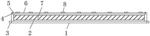
图1为本实用新型的整体结构示意图。FIG. 1 is a schematic diagram of the overall structure of the present invention.
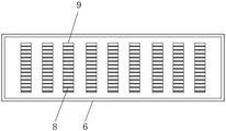
图2为本实用新型屏蔽板俯视结构示意图。FIG. 2 is a schematic top view of the structure of the shielding plate of the present invention.
图3为本实用新型固定件俯视结构示意图。FIG. 3 is a schematic top view of the structure of the fixing member of the present invention.
图中:1、壳体;2、减震垫;3、固定件;4、卡槽;5、螺丝;6、屏蔽板;7、线路板本体;8、散热鳍片;9、安装口;10、通孔。In the figure: 1. Shell; 2. Shock-absorbing pad; 3. Fixing part; 4. Card slot; 5. Screw; 6. Shielding plate; 7. Circuit board body; 8. Heat dissipation fin; 10. Through holes.
具体实施方式Detailed ways
为使本实用新型实现的技术手段、创作特征、达成目的与功效易于明白了解,下面结合具体实施方式,进一步阐述本实用新型。In order to make the technical means, creation features, achievement goals and effects of the present invention easy to understand and understand, the present invention will be further described below with reference to the specific embodiments.
在本实用新型的描述中,需要说明的是,术语“上”、“下”、“内”、“外”“前端”、“后端”、“两端”、“一端”、“另一端”等指示的方位或位置关系为基于附图所示的方位或位置关系,仅是为了便于描述本实用新型和简化描述,而不是指示或暗示所指的装置或元件必须具有特定的方位、以特定的方位构造和操作,因此不能理解为对本实用新型的限制。此外,术语“第一”、“第二”仅用于描述目的,而不能理解为指示或暗示相对重要性。In the description of the present invention, it should be noted that the terms "upper", "lower", "inner", "outer", "front end", "rear end", "two ends", "one end", "the other end" The orientation or positional relationship indicated by "" etc. is based on the orientation or positional relationship shown in the accompanying drawings, and is only for the convenience of describing the present invention and simplifying the description, rather than indicating or implying that the indicated device or element must have a specific orientation, so as to The specific orientation configuration and operation is therefore not to be construed as a limitation of the present invention. Furthermore, the terms "first" and "second" are used for descriptive purposes only and should not be construed to indicate or imply relative importance.
在本实用新型的描述中,需要说明的是,除非另有明确的规定和限定,术语“安装”、“设置有”、“连接”等,应做广义理解,例如“连接”,可以是固定连接,也可以是可拆卸连接,或一体地连接;可以是机械连接,也可以是电连接;可以是直接相连,也可以通过中间媒介间接相连,可以是两个元件内部的连通。对于本领域的普通技术人员而言,可以具体情况理解上述术语在本实用新型中的具体含义。In the description of the present utility model, it should be noted that, unless otherwise expressly specified and limited, the terms "installed", "provided with", "connected", etc., should be understood in a broad sense, for example, "connected" may be a fixed The connection can also be a detachable connection, or an integral connection; it can be a mechanical connection or an electrical connection; it can be a direct connection, or an indirect connection through an intermediate medium, and it can be internal communication between two components. For those of ordinary skill in the art, the specific meanings of the above terms in the present invention can be understood in specific situations.
请参阅图1-3,本实用新型提供一种技术方案:一种具有热电分离的线路板,包括壳体1,所述壳体1的上端面固定连接有减震垫2,所述减震垫2的上端面可拆卸连接有线路板本体7,所述壳体1的上端面开设有卡槽4,所述卡槽4的内部可拆卸连接有屏蔽板6,所述屏蔽板6的上端面开设有安装口9,所述安装口9的内部固定连接有散热鳍片8,所述屏蔽板6与卡槽4通过螺丝5可拆卸连接。1-3, the present invention provides a technical solution: a circuit board with thermoelectric separation, comprising a
所述壳体1的外侧固定连接有四组固定件3,所述固定件3的上端面开设有通孔10,在对壳体1固定时,将螺栓穿入通孔10中,能够对壳体1进行安装固定,所述安装口9的数量设置有多组,且安装口9为长条形结构,便于安装多组散热鳍片8,起到很好的散热作用,所述卡槽4的上端面开设有螺纹孔,便于对螺丝5的拧紧,所述壳体1的底部四角位置均开设有螺孔,便于对电路板本体7的安装固定。The outer side of the
工作原理:通过设置有屏蔽板6和散热鳍片8,使其相互配合使用,从而将热电分离技术与抗电磁干扰技术结合起来,使屏蔽板6既起着屏蔽外部电磁对线路板的干扰作用,又能起到散热的作用,节省空间及节约成本,提高了线路板的使用效果。Working principle: The
尽管已经示出和描述了本实用新型的实施例,对于本领域的普通技术人员而言,可以理解在不脱离本实用新型的原理和精神的情况下可以对这些实施例进行多种变化、修改、替换和变型,本实用新型的范围由所附权利要求及其等同物限定。Although the embodiments of the present invention have been shown and described, it will be understood by those skilled in the art that various changes and modifications can be made to these embodiments without departing from the principles and spirit of the present invention , alternatives and modifications, the scope of the present invention is defined by the appended claims and their equivalents.
Claims (5)
Priority Applications (1)
| Application Number | Priority Date | Filing Date | Title |
|---|---|---|---|
| CN202220304964.5U CN217470666U (en) | 2022-02-16 | 2022-02-16 | A circuit board with thermoelectric separation |
Applications Claiming Priority (1)
| Application Number | Priority Date | Filing Date | Title |
|---|---|---|---|
| CN202220304964.5U CN217470666U (en) | 2022-02-16 | 2022-02-16 | A circuit board with thermoelectric separation |
Publications (1)
| Publication Number | Publication Date |
|---|---|
| CN217470666U true CN217470666U (en) | 2022-09-20 |
Family
ID=83264026
Family Applications (1)
| Application Number | Title | Priority Date | Filing Date |
|---|---|---|---|
| CN202220304964.5U Expired - Fee Related CN217470666U (en) | 2022-02-16 | 2022-02-16 | A circuit board with thermoelectric separation |
Country Status (1)
| Country | Link |
|---|---|
| CN (1) | CN217470666U (en) |
-
2022
- 2022-02-16 CN CN202220304964.5U patent/CN217470666U/en not_active Expired - Fee Related
Similar Documents
| Publication | Publication Date | Title |
|---|---|---|
| CN111615305A (en) | Plug box and magnetic resonance system | |
| CN116033730A (en) | Chassis and flight equipment | |
| CN113923966A (en) | Circuit board assembly and electronic equipment | |
| CN209749010U (en) | Motherboard and its cooling device | |
| CN218959371U (en) | Heat dissipation and anti-interference shell structure for power amplifier circuit | |
| CN221056891U (en) | Edge server | |
| CN117336945A (en) | Heat dissipation device of vehicle host and automobile | |
| CN112034941A (en) | Chip with novel framework | |
| CN201993600U (en) | Easy-radiating industrial personal computer | |
| CN210928430U (en) | Inverter heat dissipation device for photovoltaic | |
| CN219352186U (en) | High-frequency high-speed circuit board based on high-thickness-diameter deep hole electroplating technology | |
| CN210093835U (en) | A heat abstractor and car machine for car machine | |
| CN220874410U (en) | Frequency converter | |
| CN223911227U (en) | Processor cardboard heat radiation structure | |
| CN222776474U (en) | Circuit board with heat dissipation effect | |
| CN220933456U (en) | Double heat dissipation device for computer | |
| CN220629928U (en) | Built-in heat abstractor for electronic instrument and meter | |
| CN219269447U (en) | Switch power supply | |
| CN215991724U (en) | Circuit board with heat dissipation function | |
| CN116234245B (en) | A conductive cooling and heat dissipation device for ultra-large power consumption electronic components | |
| CN219019121U (en) | Be used for anti-interference circuit board | |
| CN219019125U (en) | A PCB board | |
| CN206620403U (en) | Radiator structure | |
| CN219612413U (en) | Heat radiation structure of mobile phone shielding case | |
| CN219179863U (en) | Multi-slot VPX chassis based on aluminum temperature-equalizing plate heat dissipation |
Legal Events
| Date | Code | Title | Description |
|---|---|---|---|
| GR01 | Patent grant | ||
| GR01 | Patent grant | ||
| TR01 | Transfer of patent right |
Effective date of registration: 20230824 Address after: Building 9, Phase 2, Tian'an Yungu Industrial Park, Gangtou Community, Bantian Street, Longgang District, Shenzhen City, Guangdong Province, 518000, 2020 Patentee after: SHENZHEN SHUOTAIKE ELECTRONIC TECHNOLOGY Co.,Ltd. Address before: 204, Office Building, Zhaoqing Huiyitong Electronic Technology Co., Ltd., No. 40, Yingbin Avenue, High-tech Zone, Zhaoqing City, Guangdong Province, 526238 Patentee before: Zhaoqing High-tech Zone Huadi Electronic Technology Co.,Ltd. |
|
| TR01 | Transfer of patent right | ||
| CF01 | Termination of patent right due to non-payment of annual fee |
Granted publication date: 20220920 |
|
| CF01 | Termination of patent right due to non-payment of annual fee |