Anti-electricity-stealing equipment with clean effect
Technical Field
The utility model belongs to the technical field of it is clean, specifically be an anti-electricity-stealing equipment with clean effect.
Background
Electric power is the main energy of economic construction and people's life, and under the impetus of few users in the power supply process of electric power system in the interest, adopt various illegal means to implement the action of stealing electricity, in order to prevent that the action of stealing electricity can install anti-electricity-stealing equipment and monitor usually.
The existing anti-electricity-stealing equipment is inconvenient to clean the interior and is easy to influence the operation of internal elements after being used for a long time.
SUMMERY OF THE UTILITY MODEL
To the above situation, for overcoming prior art's defect, the utility model provides an anti-electricity-stealing equipment with clean effect, effectual solved present anti-electricity-stealing equipment be not convenient for clear up inside, long-time use influences the problem of inside component operation easily.
In order to achieve the above object, the utility model provides a following technical scheme: the utility model provides an anti-electricity-stealing equipment with clean effect, includes the box, L type shifting chute has all been seted up to the inside both sides of box, and the inside one side of box is connected with the mounting panel, and mounting panel one side both ends are all rotated and are connected with first magnet, and mounting panel one side is connected with the clearance subassembly.
Preferably, one side of the outside of the box body is connected with a first electric telescopic rod, one end of the first electric telescopic rod is connected with a connecting plate, and one end of the connecting plate penetrates through the box body and extends to the inside of the box body to be connected with a second magnet.
Preferably, the clearance subassembly is including installing in the biax motor of mounting panel both sides, and the biax motor both sides all are connected with the pivot, and pivot one end is connected with the gear, and gear one side meshing has the pinion rack, and pinion rack one end is connected with L type shifting chute inner wall one side, and the outside cover of pivot is equipped with the extension board, and extension board one side is connected with the mounting panel.
Preferably, the cleaning assembly further comprises a suction fan arranged at the middle part of one side of the mounting plate, the two sides of the suction fan are both connected with air suction hoses, one end of each air suction hose is connected with an air suction plate, one side of each air suction plate is connected with an ash suction cover, the two ends of one side of each air suction plate are both connected with a second electric telescopic rod, and one end of each second electric telescopic rod is connected with one side of the mounting plate.
Preferably, the gear is located inside an L-shaped moving groove, and the L-shaped moving groove is directly larger than the diameter of the gear.
Preferably, the connecting plate runs through the box body and is provided with a connecting hole, the connecting plate is located inside the connecting hole, and the connecting plate is connected with the box body in a sliding mode.
Preferably, one end of the second electric telescopic rod penetrates through and extends to one side outside the mounting plate, and is connected with a fixing frame, and one side of the fixing frame is connected with one side of the mounting plate.
Compared with the prior art, the beneficial effects of the utility model are that:
(1) the utility model discloses, through the setting of clearance subassembly, the second electric telescopic link stretches out and makes the suction hood be located equipment one side, and the suction fan absorbs equipment surface dust through the suction hood, then the biax motor drives the pivot rotation, under the meshing transmission of gear and pinion rack, makes the suction hood carry out all-round clearance to equipment to make the device can realize automatic clearance, avoid equipment not clear up for a long time and influence equipment operation;
(2) through the setting of first electric telescopic handle, connecting plate, first magnet and second magnet, the flexible connecting plate that drives of first electric telescopic handle removes, makes the mounting panel slide in L type shifting chute inside, makes the mounting panel change direction of motion then to make the mounting panel remove when not needing the use, avoid influencing the box inner space.
Drawings
The accompanying drawings are included to provide a further understanding of the invention, and are incorporated in and constitute a part of this specification, illustrate embodiments of the invention, and together with the description serve to explain the invention and not to limit the invention.
In the drawings:
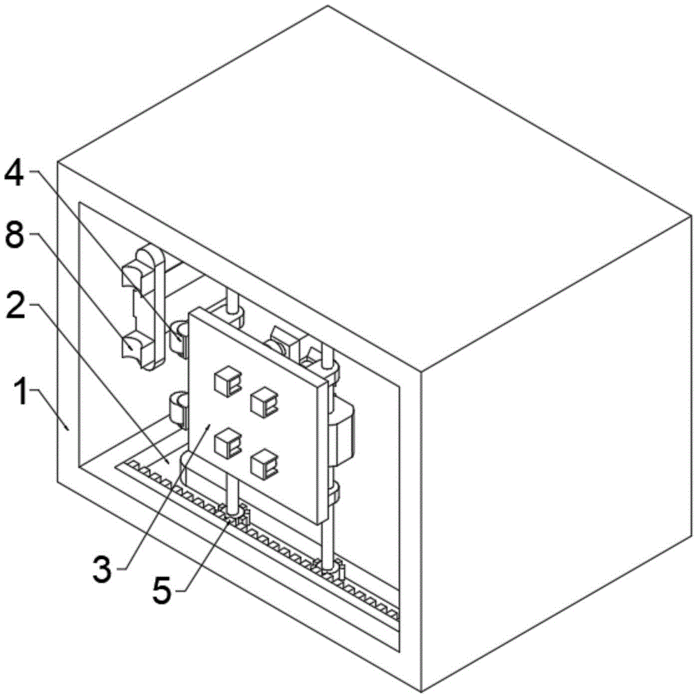
FIG. 1 is a schematic structural view of the present invention;
fig. 2 is a schematic view of the structure of the L-shaped moving chute of the present invention;
FIG. 3 is a schematic view of the mounting structure of the connecting plate of the present invention;
FIG. 4 is a schematic structural view of the cleaning assembly of the present invention;
FIG. 5 is a schematic view of the connection structure of the dust hood of the present invention;
in the figure: 1. a box body; 2. an L-shaped moving groove; 3. mounting a plate; 4. a first magnet; 5. cleaning the assembly; 51. a double-shaft motor; 52. a rotating shaft; 53. a gear; 54. a toothed plate; 55. a support plate; 56. a suction fan; 57. a suction hose; 58. a suction plate; 59. a dust suction cover; 510. a second electric telescopic rod; 6. a first electric telescopic rod; 7. a connecting plate; 8. a second magnet.
Detailed Description
The technical solutions in the embodiments of the present invention will be clearly and completely described below with reference to the drawings in the embodiments of the present invention, and it is obvious that the described embodiments are only some embodiments of the present invention, not all embodiments; based on the embodiments in the present invention, all other embodiments obtained by a person skilled in the art without creative work belong to the protection scope of the present invention.
In the first embodiment, as shown in fig. 1-5, the utility model comprises a box body 1, L-shaped moving grooves 2 are respectively arranged on two sides of the interior of the box body 1, a mounting plate 3 is connected to one side of the interior of the box body 1, a first magnet 4 is rotatably connected to both ends of one side of the mounting plate 3, and a cleaning assembly 5 is connected to one side of the mounting plate 3;
the external one side of box 1 is connected with first electric telescopic handle 6, and 6 one end of first electric telescopic handle are connected with connecting plate 7, and 7 one ends of connecting plate run through and extend to 1 inside department of box and be connected with second magnet 8, and connecting plate 7 runs through 1 department of box and has seted up the connecting hole, and connecting plate 7 is located inside the connecting hole, connecting plate 7 and 1 sliding connection of box.
In the second embodiment, on the basis of the first embodiment, the cleaning assembly 5 includes a dual-shaft motor 51 installed at two sides of the mounting plate 3, two sides of the dual-shaft motor 51 are both connected with a rotating shaft 52, one end of the rotating shaft 52 is connected with a gear 53, one side of the gear 53 is engaged with a toothed plate 54, one end of the toothed plate 54 is connected with one side of the inner wall of the L-shaped moving groove 2, a supporting plate 55 is sleeved outside the rotating shaft 52, one side of the supporting plate 55 is connected with the mounting plate 3, the gear 53 is located inside the L-shaped moving groove 2, and the diameter of the L-shaped moving groove 2 is directly larger than that of the gear 53;
the cleaning assembly 5 further comprises a suction fan 56 mounted in the middle of one side of the mounting plate 3, suction hoses 57 are connected to two sides of the suction fan 56, one end of each suction hose 57 is connected with a suction plate 58, one side of each suction plate 58 is connected with an ash suction cover 59, two ends of one side of each suction plate 58 are connected with second electric telescopic rods 510, one end of each second electric telescopic rod 510 is connected with one side of the mounting plate 3, one end of each second electric telescopic rod 510 extends to one side of the outer portion of the mounting plate 3 in a penetrating mode and is connected with a fixing frame, and one side of each fixing frame is connected with one side of the mounting plate 3;
in an initial state, the first magnet 4 and the second magnet 8 are attracted, the gear 53 is not in contact with the toothed plate 54, when the interior of the box body 1 needs to be cleaned, the second electric telescopic rod 510 extends to one side to drive the air suction plate 58 to move, so that the dust suction cover 59 is positioned at one side of the equipment body, the air suction fan 56 absorbs dust on the surface of the equipment body through the dust suction cover 59, then the first electric telescopic rod 6 extends to drive the connecting plate 7 to move, the connecting plate 7 drives the second magnet 8 to move, the first magnet 4 and the second magnet 8 are attracted, the second magnet 8 moves to drive the mounting plate 3 to move, the mounting plate 3 drives the gear 53 to move, when one end of the gear 53 is meshed with the toothed plate 54, the double-shaft motor 51 drives the rotating shaft 52 to rotate, the rotating shaft 52 drives the gear 53 to rotate, under the cooperation of the toothed plate 54, the mounting plate 3 moves to one side, and simultaneously the first electric telescopic rod 6 continues to drive the connecting plate 7 to move, make another gear 53 and pinion rack 54 meshing, and then make mounting panel 3 become along pinion rack 54 lateral shifting by longitudinal movement, biax motor 51 continues to drive gear 53 and removes, make first magnet 4 break away from with second magnet 8, and then make the omnidirectional of dust absorption cover 59 clear up the equipment body surface, after the clearance is accomplished, biax motor 51 drives pivot 52 and rotates to the opposite side, pivot 52 drives gear 53 and rotates, under the cooperation of pinion rack 54, make mounting panel 3 move to the opposite side, make first magnet 4 and second magnet 8 contact, then make first magnet 4 and second magnet 8 adsorb, first electric telescopic handle 6 stretches out and draws back and drives connecting plate 7 and remove, connecting plate 7 drives mounting panel 3 and removes, and then make mounting panel 3 change into longitudinal movement by lateral shifting, thereby make mounting panel 3 remove to the normal position.
The working principle is as follows: when the device is used, in an initial state, the first magnet 4 and the second magnet 8 are adsorbed, the gear 53 is not in contact with the toothed plate 54, when the interior of the box body 1 needs to be cleaned, the second electric telescopic rod 510 extends to one side to drive the air suction plate 58 to move, so that the dust suction cover 59 is positioned at one side of the device body, the air suction fan 56 absorbs dust on the surface of the device body through the dust suction cover 59, then the first electric telescopic rod 6 extends to drive the connecting plate 7 to move, the connecting plate 7 drives the second magnet 8 to move, the first magnet 4 and the second magnet 8 are adsorbed, the second magnet 8 moves to drive the mounting plate 3 to move, the mounting plate 3 drives the gear 53 to move, when one end of the gear 53 is engaged with the toothed plate 54, the double-shaft motor 51 drives the rotating shaft 52 to rotate, the rotating shaft 52 drives the gear 53 to rotate, the mounting plate 3 moves to one side under the cooperation of the toothed plate 54, and simultaneously the first electric telescopic rod 6 continues to drive the connecting plate 7 to move, make another gear 53 and pinion rack 54 meshing, and then make mounting panel 3 become along pinion rack 54 lateral shifting by longitudinal movement, biax motor 51 continues to drive gear 53 and removes, make first magnet 4 break away from with second magnet 8, and then make the omnidirectional of dust absorption cover 59 clear up the equipment body surface, after the clearance is accomplished, biax motor 51 drives pivot 52 and rotates to the opposite side, pivot 52 drives gear 53 and rotates, under the cooperation of pinion rack 54, make mounting panel 3 move to the opposite side, make first magnet 4 and second magnet 8 contact, then make first magnet 4 and second magnet 8 adsorb, first electric telescopic handle 6 stretches out and draws back and drives connecting plate 7 and remove, connecting plate 7 drives mounting panel 3 and removes, and then make mounting panel 3 change into longitudinal movement by lateral shifting, thereby make mounting panel 3 remove to the normal position.