CN217438452U - A textile drying device - Google Patents
A textile drying device Download PDFInfo
- Publication number
- CN217438452U CN217438452U CN202220510842.1U CN202220510842U CN217438452U CN 217438452 U CN217438452 U CN 217438452U CN 202220510842 U CN202220510842 U CN 202220510842U CN 217438452 U CN217438452 U CN 217438452U
- Authority
- CN
- China
- Prior art keywords
- drying
- drying box
- dewatering
- textile
- water removal
- Prior art date
- Legal status (The legal status is an assumption and is not a legal conclusion. Google has not performed a legal analysis and makes no representation as to the accuracy of the status listed.)
- Expired - Fee Related
Links
Images
Landscapes
- Auxiliary Weaving Apparatuses, Weavers' Tools, And Shuttles (AREA)
Abstract
Description
技术领域technical field
本实用新型涉及纺织设备技术领域,尤其涉及一种纺织布烘干装置。The utility model relates to the technical field of textile equipment, in particular to a drying device for textile cloth.
背景技术Background technique
纺织布,即是纺织面料,按织造方法分,其有纬编针织面料和经编针织面料两类,纬编针织面料常以低弹涤纶丝或异型涤纶丝、锦纶丝、棉纱和毛纱等为原料,采用平针组织、变化平针组织、罗纹平针组织、双罗纹平针组织、提花组织和毛圈组织等,在各种纬编机上编织而成的布料。在纺织过程中,往往需要采用对纺织完成的布料进行漂洗,漂洗完成后往往需要利用烘干装置对纺织布进行烘干,而纺织布上水分较多,直接烘干效率较低。Textile fabrics are textile fabrics. According to the weaving method, there are two types of weft knitted fabrics and warp knitted fabrics. Weft knitted fabrics are often made of low-elastic polyester yarn or special-shaped polyester yarn, nylon yarn, cotton yarn and wool yarn. The raw materials are fabrics knitted on various weft knitting machines using plain stitch, variable plain stitch, rib plain stitch, double rib plain stitch, jacquard and terry. In the weaving process, it is often necessary to rinse the woven fabrics. After rinsing, the woven fabrics are often dried with a drying device. However, there is more moisture on the woven fabrics, and the direct drying efficiency is low.
实用新型内容Utility model content
本实用新型的目的是为了解决现有技术中存在的缺点,而提出的一种纺织布烘干装置。The purpose of the utility model is to propose a drying device for textile cloth in order to solve the shortcomings existing in the prior art.
为了实现上述目的,本实用新型采用了如下技术方案:一种纺织布烘干装置,包括烘干箱,在烘干箱内转动连接多组导向辊,在烘干箱内连接烘干组件,在烘干箱的一侧连接去水箱,去水箱通过连通孔连通所述烘干箱,在去水箱内设有两组去水组件,在两组去水组件中间设有刮水组件。In order to achieve the above purpose, the utility model adopts the following technical scheme: a textile cloth drying device, comprising a drying box, a plurality of groups of guide rollers are rotatably connected in the drying box, drying components are connected in the drying box, and One side of the drying box is connected to a water removal tank, and the water removal tank is connected to the drying box through a communication hole.
优选地,所述去水组件包括转动连接在所述去水箱内的固定辊,在固定辊的下方设有第一驱动件,在第一驱动件的驱动杆上连接去水辊,去水辊与所述固定辊对应设置。Preferably, the dewatering assembly includes a fixed roller rotatably connected in the dewatering tank, a first driving member is arranged below the fixed roller, and a driving rod of the first driving member is connected to the dewatering roller, and the dewatering roller Corresponding to the fixed roller.
优选地,所述刮水组件包括两个上下相对设置的弹性件,在每个弹性件上均连接刮水板,两个刮水板相对设置。Preferably, the wiper assembly includes two elastic members disposed up and down opposite each other, each elastic member is connected with a wiper blade, and the two wiper blades are disposed opposite to each other.
优选地,在所述去水箱内连接过滤板,过滤板将所述去水箱分隔为去水腔和蓄水腔,在去水箱上设有进口,进口连通所述去水腔,在去水箱的侧面下方连接出水管,出水管连通所述蓄水腔。Preferably, a filter plate is connected in the water removal tank, the filter plate divides the water removal tank into a water removal chamber and a water storage chamber, an inlet is provided on the water removal tank, the inlet is connected to the water removal chamber, and the water removal tank is provided with an inlet. A water outlet pipe is connected below the side surface, and the water outlet pipe communicates with the water storage cavity.
优选地,所述烘干组件包括热气管,热气管设置在所述烘干箱内的上方,在热气管上连接一组分气管,分气管均竖直向下设置,在每个分气管的竖直两侧均设有一排出气口。Preferably, the drying assembly includes a hot gas pipe, the hot gas pipe is arranged above the drying box, a group of gas pipes is connected to the hot gas pipe, and the gas split pipes are all arranged vertically downward. Both vertical sides are provided with an exhaust port.
优选地,在所述烘干箱内设置烫熨组件,烫熨组件包括配合设置的承压板和熨斗,承压板连接在所述烘干箱内,熨斗通过第二驱动件驱动连接,第二驱动件连接在所述烘干箱上。Preferably, an ironing assembly is arranged in the drying box, and the ironing assembly includes a pressure-bearing plate and an iron that are matched with each other, the pressure-bearing plate is connected in the drying box, the iron is driven and connected through a second driving member, and the first Two driving parts are connected to the drying box.
本实用新型的优点在于:本实用新型所提供的一种纺织布烘干装置在对纺织布烘干前,通过去水组件对纺织布进行去水处理,将纺织布上的大部分水分去除,能够提高后续的烘干效率,且在烘干后提供烫熨处理,防止布料出现褶皱的现象。The advantage of the utility model is that: before the textile cloth drying device provided by the utility model, the textile cloth is subjected to dewatering treatment through a dewatering component to remove most of the moisture on the textile cloth, The subsequent drying efficiency can be improved, and ironing treatment can be provided after drying to prevent the fabric from wrinkling.
附图说明Description of drawings
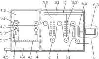
图1是本实用新型所提供的一种纺织布烘干装置的原理结构示意图;Fig. 1 is the principle structure schematic diagram of a kind of textile cloth drying device provided by the utility model;
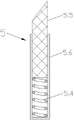
图2是第二实施例中去水组件的结构示意图。FIG. 2 is a schematic diagram of the structure of the dewatering assembly in the second embodiment.
具体实施方式Detailed ways
下面将结合本实用新型实施例中的附图,对本实用新型实施例中的技术方案进行清楚、完整地描述,显然,所描述的实施例仅仅是本实用新型一部分实施例,而不是全部的实施例。基于本实用新型中的实施例,本领域普通技术人员在没有做出创造性劳动前提下所获得的所有其他实施例,都属于本实用新型保护的范围。The technical solutions in the embodiments of the present utility model will be clearly and completely described below with reference to the accompanying drawings in the embodiments of the present utility model. Obviously, the described embodiments are only a part of the embodiments of the present utility model, rather than all the implementations. example. Based on the embodiments of the present invention, all other embodiments obtained by those of ordinary skill in the art without creative work fall within the protection scope of the present invention.
在本实用新型的描述中,需要理解的是,术语“中心”、“纵向”、“横向”、“长度”、“宽度”、“厚度”、“上”、“下”、“前”、“后”、“左”、“右”、“竖直”、“水平”、“顶”、“底”、“内”、“外”、“顺时针”、“逆时针”等指示的方位或位置关系为基于附图所示的方位或位置关系,仅是为了便于描述本实用新型和简化描述,而不是指示或暗示所指的设备或元件必须具有特定的方位、以特定的方位构造和操作,因此不能理解为对本实用新型的限制。In the description of the present invention, it should be understood that the terms "center", "longitudinal", "lateral", "length", "width", "thickness", "upper", "lower", "front", "Back", "Left", "Right", "Vertical", "Horizontal", "Top", "Bottom", "Inner", "Outer", "Clockwise", "Counterclockwise" etc. Or the positional relationship is based on the orientation or positional relationship shown in the accompanying drawings, which is only for the convenience of describing the present invention and simplifying the description, rather than indicating or implying that the referred device or element must have a specific orientation, be constructed in a specific orientation and operation, so it cannot be construed as a limitation to the present invention.
如图1所示,本实用新型提供的一种纺织布烘干装置,包括烘干箱1,在烘干箱1内转动连接多组导向辊2,使纺织布依次穿过多组导向辊2时呈波浪形状,从而能够更好的烘干纺织布。As shown in FIG. 1 , a textile cloth drying device provided by the present utility model includes a drying box 1, in which multiple groups of
在烘干箱1内连接烘干组件3,所述烘干组件3包括热气管3.1,热气管3.1的一端设置在烘干箱1内,另一端连接加热装置,加热装置为现有装置,能够为热气管3.1提供加热后的气体,热气管3.1设置在所述烘干箱1内的上方,在热气管3.1上连接一组分气管3.2,分气管3.2均竖直向下设置,在每个分气管3.2的竖直两侧均设有一排出气口3.3,每个分气管3.2刚好处于波浪状纺织布的弯曲处,使出气口3.3朝向纺织布,使分气管3.2内的热气能够更好的吹在纺织布上,以便于对纺织布更好的烘干。A drying assembly 3 is connected in the drying box 1. The drying assembly 3 includes a hot gas pipe 3.1. One end of the hot gas pipe 3.1 is arranged in the drying box 1, and the other end is connected to a heating device. The heating device is an existing device, which can Provide heated gas for the hot gas pipe 3.1, the hot gas pipe 3.1 is arranged above the drying box 1, a group of gas pipes 3.2 are connected to the hot gas pipe 3.1, and the gas distribution pipes 3.2 are arranged vertically downward. There is an air outlet 3.3 on both vertical sides of the air distribution pipe 3.2, each air distribution pipe 3.2 is just at the bend of the wavy textile cloth, so that the air outlet 3.3 faces the textile cloth, so that the hot air in the air distribution pipe 3.2 can be better blown On woven fabrics for better drying of woven fabrics.
在烘干箱1内设置烫熨组件6,烫熨组件6包括配合设置的承压板6.1和熨斗6.2,承压板6.1通过螺栓固定在所述烘干箱1内,熨斗6.2通过第二驱动件6.3驱动连接,第二驱动件6.3可以为油缸、气缸或者电动推杆,在本实施例中,第二驱动件6.3优先选用油缸,第二驱动件6.3通过螺栓固定在所述烘干箱1的外侧面,在烘干箱1上设有通孔用于穿过第二驱动杆6.3的驱动杆,在第二驱动杆6.3的驱动杆上连接熨斗6.2,纺织布在烘干过后会经过承压板6.1与熨斗6.2之间,通过第二驱动件6.3带动熨斗6.2向承压板6.1的方向运动,使熨斗6.2对纺织布进行烫熨,防止纺织布出现褶皱。An ironing assembly 6 is arranged in the drying box 1, and the ironing assembly 6 includes a pressure bearing plate 6.1 and an iron 6.2 which are arranged in a matched manner, the pressure bearing plate 6.1 is fixed in the drying box 1 by bolts, and the iron 6.2 is driven by the second The second driving member 6.3 is connected by driving, and the second driving member 6.3 can be an oil cylinder, an air cylinder or an electric push rod. In this embodiment, the second driving member 6.3 is preferably an oil cylinder, and the second driving member 6.3 is fixed to the drying box 1 by bolts. On the outer side of the drying box 1, there is a through hole for passing through the driving rod of the second driving rod 6.3, and the iron 6.2 is connected to the driving rod of the second driving rod 6.3. After drying, the textile cloth will pass through the bearing. Between the pressing plate 6.1 and the iron 6.2, the second driving member 6.3 drives the iron 6.2 to move in the direction of the pressure-bearing plate 6.1, so that the iron 6.2 irons the textile cloth to prevent the textile cloth from wrinkling.
在烘干箱1的一侧连接去水箱4,去水箱4通过连通孔连通所述烘干箱1,在去水箱4内连接过滤板4.1,过滤板4.1将所述去水箱4分隔为去水腔4.3和蓄水腔4.4,在去水箱4上设有进口4.2,进口连通所述去水腔4.3,在去水箱4的侧面下方连接出水管4.5,出水管4.5连通所述蓄水腔4.4。A water removal tank 4 is connected to one side of the drying box 1, the water removal tank 4 is connected to the drying box 1 through a communication hole, and a filter plate 4.1 is connected in the water removal tank 4, and the filter plate 4.1 separates the water removal tank 4 into water removal. The cavity 4.3 and the water storage cavity 4.4 are provided with an inlet 4.2 on the water removal tank 4, the inlet is connected to the water removal chamber 4.3, and a water outlet pipe 4.5 is connected below the side of the water removal tank 4, and the water outlet pipe 4.5 is connected to the water storage chamber 4.4.
在去水腔4.3内设有两组去水组件5,所述去水组件5包括转动连接在所述去水箱4内的固定辊5.1,在固定辊5.1的下方设有第一驱动件5.2,第一驱动件5.2可以为油缸、气缸或者电动推杆,在本实施例中,第一驱动件5.2优先选用油缸,在第一驱动件5.2的驱动杆上连接去水辊5.3,去水辊5.3与所述固定辊5.1对应设置,当纺织布穿过固定辊5.1和去水辊5.3时,通过第一驱动件5.2带动去水辊5.3向上运动,将纺织布上蕴含的水分挤出。Two groups of dewatering
纺织布通过进口4.2进入去水箱4内,通过第一个去水组件5对纺织布进行初步的去水,最后再通过第二个去水组件5对纺织布进行再一次去水,最大程度的将纺织布上蕴含的水分挤出,挤出水分后的纺织布通过连通孔进入烘干箱1内,纺织布依次通过导向辊2,使烘干组件3对纺织布进行烘干,在通过烘干箱1的出口输出之前,启动第二驱动件6.3带动熨斗6.2向承压板6.1的方向运动,使熨斗6.2对纺织布进行烫熨,防止纺织布出现褶皱。The textile cloth enters the dewatering tank 4 through the inlet 4.2, the textile cloth is initially dewatered through the
实施例二:在实施例一的基础上,去水组件5还可以为以下结构:如图2所示,所述去水组件5包括两个上下相对设置的弹性件5.4,在本实施例中弹性件5.4具体为弹簧,在每个弹性件5.4的上方均连接刮水板5.5,刮水板5.5的上端面呈斜面,两个刮水板5.5相对设置,使两个刮水板5.5能够紧压在纺织布的两侧,从而将纺织布内蕴含的水分挤压出来。Embodiment 2: On the basis of Embodiment 1, the
为了防止纺织布在移动时带动刮水板5.5倾斜,从而影响刮水板5.5的刮水效果,在每个刮水板5.5的外侧均套接导向套5.6,导向套5.6为矩形管,导向套5.6焊接在所述过滤板4.1的上方,在导向套5.6内设置相应的所述弹性件5.4,使刮水板5.5能够在导向套5.6内导向滑动。In order to prevent the textile cloth from driving the wiper blade 5.5 to incline when moving, thereby affecting the wiping effect of the wiper blade 5.5, a guide sleeve 5.6 is sleeved on the outer side of each wiper blade 5.5, and the guide sleeve 5.6 is a rectangular tube. 5.6 is welded on the top of the filter plate 4.1, and the corresponding elastic member 5.4 is arranged in the guide sleeve 5.6, so that the wiper blade 5.5 can guide and slide in the guide sleeve 5.6.
以上显示和描述了本实用新型的基本原理、主要特征和本实用新型的优点。本行业的技术人员应该了解,本实用新型不受上述实施例的限制,上述实施例和说明书中描述的仅为本实用新型的优选例,并不用来限制本实用新型,在不脱离本实用新型精神和范围的前提下,本实用新型还会有各种变化和改进,这些变化和改进都落入要求保护的本实用新型范围内。本实用新型要求保护范围由所附的权利要求书及其等效物界定。The basic principles, main features and advantages of the present invention have been shown and described above. Those skilled in the art should understand that the present invention is not limited by the above-mentioned embodiments. The above-mentioned embodiments and descriptions are only preferred examples of the present invention and are not intended to limit the present invention. Under the premise of the spirit and scope, the present invention will have various changes and improvements, and these changes and improvements all fall within the scope of the claimed invention. The claimed scope of the present invention is defined by the appended claims and their equivalents.
Claims (6)
Priority Applications (1)
| Application Number | Priority Date | Filing Date | Title |
|---|---|---|---|
| CN202220510842.1U CN217438452U (en) | 2022-03-10 | 2022-03-10 | A textile drying device |
Applications Claiming Priority (1)
| Application Number | Priority Date | Filing Date | Title |
|---|---|---|---|
| CN202220510842.1U CN217438452U (en) | 2022-03-10 | 2022-03-10 | A textile drying device |
Publications (1)
| Publication Number | Publication Date |
|---|---|
| CN217438452U true CN217438452U (en) | 2022-09-16 |
Family
ID=83216494
Family Applications (1)
| Application Number | Title | Priority Date | Filing Date |
|---|---|---|---|
| CN202220510842.1U Expired - Fee Related CN217438452U (en) | 2022-03-10 | 2022-03-10 | A textile drying device |
Country Status (1)
| Country | Link |
|---|---|
| CN (1) | CN217438452U (en) |
-
2022
- 2022-03-10 CN CN202220510842.1U patent/CN217438452U/en not_active Expired - Fee Related
Similar Documents
| Publication | Publication Date | Title |
|---|---|---|
| CN110296593A (en) | A kind of textile fabric drying equipment | |
| CN215909540U (en) | Dewatering and drying device for textile fabric | |
| CN215366330U (en) | Shuttle is knitted yarn-dyed plain cloth production and is used environmental protection bleaching device | |
| CN212294055U (en) | Washing device for printing and dyeing knitted fabric | |
| CN109402907A (en) | A kind of reactive dye carry out the device of salt-free dyeing to un-scoured and unbleached cotton textile | |
| CN215490857U (en) | Drying treatment device for improving comprehensive yarn dewatering efficiency | |
| CN211256320U (en) | Conveying device for textile fabric open washing | |
| CN216809277U (en) | Fabric production is with rolling setting device who prevents fold | |
| CN108517637B (en) | Cloth rolling mill | |
| CN210394836U (en) | Dewatering equipment for textile fabrics | |
| CN212687073U (en) | Cloth double-sided dust collector for clothing production | |
| CN211689544U (en) | Polyester yarn environment-friendly dyeing device | |
| CN211972723U (en) | Textile fabric drying device for spinning | |
| CN202247338U (en) | Integrated scutching and dewatering equipment | |
| CN118687355A (en) | A drying device for textile processing | |
| CN216585636U (en) | Textile sizing device with waste recovery function | |
| KR20100061412A (en) | Device for cleaning and drying of textile | |
| CN105466177A (en) | Rapid textile drying machine | |
| CN208151637U (en) | A kind of weaving dryer | |
| CN210886572U (en) | Drying device for textile printing and dyeing fabric | |
| CN213142471U (en) | Printing and dyeing drying device based on cloth printing and dyeing | |
| CN220398146U (en) | Drying device for producing dacron edge woven grey cloth | |
| CN222861784U (en) | Dewatering device of water-jet loom for producing polyester cloth | |
| CN112941781A (en) | Cloth cleaning and drying device for recycling waste heat and water vapor for textile processing | |
| CN223951401U (en) | Polyester shuttle loom fabric preprocessing equipment |
Legal Events
| Date | Code | Title | Description |
|---|---|---|---|
| GR01 | Patent grant | ||
| GR01 | Patent grant | ||
| CF01 | Termination of patent right due to non-payment of annual fee | ||
| CF01 | Termination of patent right due to non-payment of annual fee |
Granted publication date: 20220916 |