SUMMERY OF THE UTILITY MODEL
An object of the utility model is to provide a sewage plant dive stirring pushes away laborsaving hoisting device of class equipment to solve the problem that proposes in the above-mentioned background art.
In order to achieve the above purpose, the utility model provides a following technical scheme: the utility model provides a laborsaving hoisting device of equipment is pushed away in dive stirring of sewage plant, the laborsaving hoisting device of equipment is pushed away in dive stirring of sewage plant includes:
the top of the base is provided with a support column;
the top of the movable block is in threaded connection with a screw, the bottom of the screw is provided with a propping block, and the top of the movable block is provided with a through hole; and
the motor is arranged at the top of the base.
Preferably, the top of the support column is provided with a cross beam, teeth are arranged on the surface of the cross beam, and the top of the cross beam is provided with threaded holes.
Preferably, the outside cover of crossbeam is equipped with the movable block, and the movable block can remove on the surface of crossbeam, and the inside logical groove area of movable block is greater than the tangent plane area of crossbeam for the movable block can reciprocate in the outside of crossbeam.
Preferably, the inside of movable block is provided with the top and holds the piece, and the screw rod is installed at the top that holds the piece in the top, and the disc is installed to the bottom of screw rod, and the disc can hold the inside rotation in the top, can make the top hold the piece and can reciprocate in the movable block after the screw rod rotates.
Preferably, the motor is installed at the top of support column, and the top of motor is connected with the worm, and support column surface mounting has drive gear, and drive gear and worm mesh, the worm rotates and can drive gear and rotate.
Preferably, the end of the driving gear is connected with a connecting gear, the connecting gear rotates along with the driving gear, a rotating gear is mounted on the surface of the supporting column, and the rotating gear is meshed with the connecting gear.
Compared with the prior art, the beneficial effects of the utility model are that:
the utility model provides a movable block can pass the through-hole at the surperficial slip of crossbeam, revolves the screw rod to twist to fix at the top of crossbeam with the movable block in the screw hole, revolves to twist the screw rod for the top is held the piece top and is held at the top of crossbeam, just can remove the movable block.
Detailed Description
In order to make the objects, technical solutions and advantages of the present invention clear and fully described, embodiments of the present invention are further described in detail below with reference to the accompanying drawings. It is to be understood that the specific embodiments described herein are merely illustrative of some embodiments of the invention and are not limiting of the invention, and that all other embodiments obtained by those of ordinary skill in the art without the exercise of inventive faculty are within the scope of the invention.
In the description of the present invention, it should be noted that the terms "center", "middle", "upper", "lower", "left", "right", "inner", "outer", "top", "bottom", "side", "vertical", "horizontal", and the like indicate orientations or positional relationships based on those shown in the drawings, and are only for convenience of description and simplicity of description, but do not indicate or imply that the referred device or element must have a specific orientation, be constructed in a specific orientation, and be operated, and thus, should not be construed as limiting the present invention. Furthermore, the terms "a," "an," "first," "second," "third," "fourth," "fifth," and "sixth" are used for descriptive purposes only and are not to be construed as indicating or implying relative importance.
In the description of the present invention, it should be noted that, unless otherwise explicitly specified or limited, the terms "mounted," "connected," and "connected" are to be construed broadly, e.g., as meaning either a fixed connection, a removable connection, or an integral connection; can be mechanically or electrically connected; they may be connected directly or indirectly through intervening media, or they may be interconnected between two elements. The specific meanings of the above terms in the present invention can be understood in a specific case to those of ordinary skill in the art.
For the purposes of simplicity and explanation, the principles of the embodiments are described by referring mainly to examples. In the following description, numerous specific details are set forth in order to provide a thorough understanding of the embodiments. It will be apparent, however, to one skilled in the art that the embodiments may be practiced without these specific details. In some instances, well-known methods and structures have not been described in detail so as not to unnecessarily obscure the embodiments. In addition, all embodiments may be used in combination with each other.
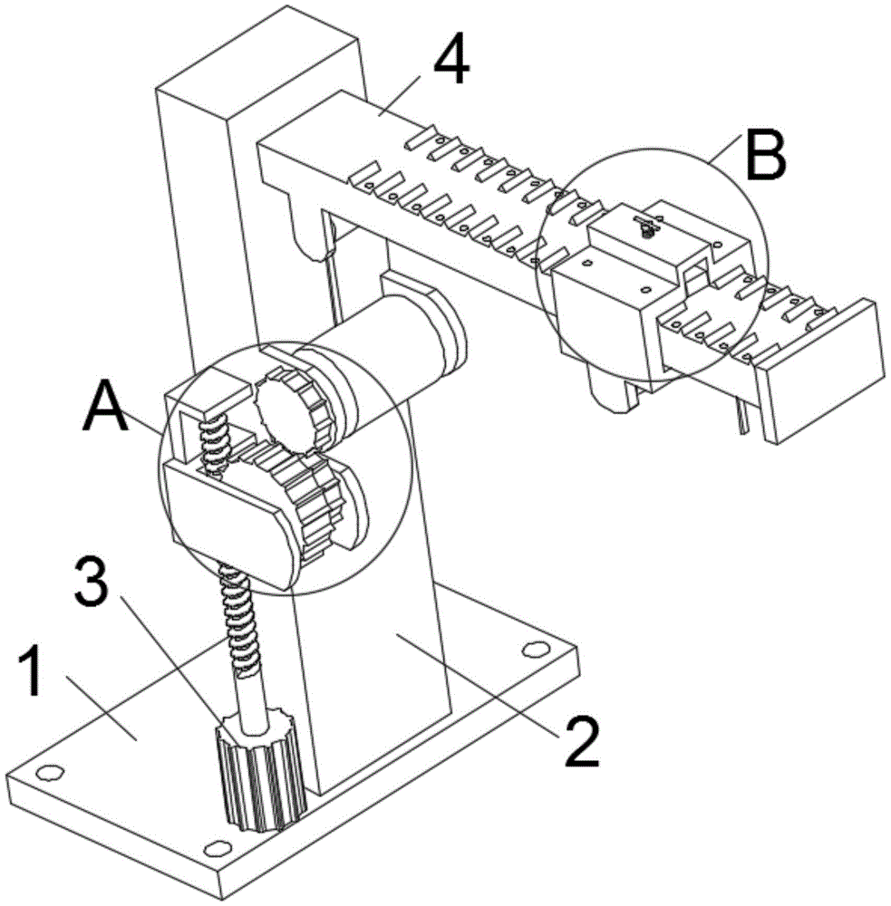
Referring to fig. 1 to 3, the present invention provides a technical solution: the utility model provides a laborsaving hoisting device of equipment is pushed away to dive stirring of sewage plant, the laborsaving hoisting device of equipment is pushed away to dive stirring of sewage plant includes: the movable block fixing device comprises a base 1, wherein a supporting column 2 is installed at the top of the base 1, a cross beam 4 is installed at the top of the supporting column 2, teeth 12 are arranged on the surface of the cross beam 4, a threaded hole 11 is formed in the top of the cross beam 4, a movable block 14 is sleeved outside the cross beam 4, the movable block 14 can move on the surface of the cross beam 4, the area of a through groove in the movable block 14 is larger than the area of a section of the cross beam 4, the movable block 14 can move up and down outside the cross beam 4, the teeth are arranged at the top of the through groove in the movable block 14, are meshed with the teeth 12, and penetrate through a through hole 10 through a screw rod to be screwed in the threaded hole 11, so that the movable block 14 is fixed;
the movable block 14 is connected with a screw rod 9 in a threaded mode at the top of the movable block 14, a jacking block 13 is installed at the bottom of the screw rod 9, a disc is installed at the bottom of the screw rod 9 and can rotate inside the disc 13, a through hole 10 is formed in the top of the movable block 14, the jacking block 13 is arranged inside the movable block 14, the screw rod 9 is installed at the top of the jacking block 13, the jacking block 13 can move up and down inside the movable block 14 after the screw rod 9 rotates, the screw rod 9 is screwed, the jacking block 13 is jacked at the top of the cross beam 4, and the movable block 14 can move;
motor 3 locates base 1's top, motor 3 is installed at the top of support column 2, motor 3's top is connected with worm 8, 2 surface mounting on support column have drive gear 7, drive gear 7 and the meshing of worm 8, worm 8 rotates and to drive gear 7 and rotate, drive gear 7's end connection has connecting gear 6, connecting gear 6 rotates along with drive gear 7, support column 2's surface mounting has rotating gear 5, rotating gear 5 and connecting gear 6 mesh, motor 3 drives worm 8 after starting and rotates, worm 8 drives drive gear 7 and rotates, connecting gear 6 rotates with drive gear 7 together, connecting gear 6 drives rotating gear 5 and rotates.
The motor 3 drives the worm 8 after starting and rotates, the worm 8 drives drive gear 7 and rotates, connecting gear 6 rotates with drive gear 7 together, connecting gear 6 drives rotating gear 5 and rotates, the tip at rotating gear 5 is connected to the elevator belt, the elevator belt is walked around the pivot of the bottom of crossbeam 4 and the pivot of movable block 14 bottom, revolve wrong screw rod 9, make top holding block 13 top hold at the top of crossbeam 4, make movable block 14 can remove, the top that 14 inside logical grooves of movable block are provided with the tooth, with tooth 12 meshing, pass through-hole 10 spiro union in screw hole 11 through the screw rod, it is fixed with movable block 14.
Although the illustrative embodiments of the present application have been described above to enable those skilled in the art to understand the present application, the present application is not limited to the scope of the embodiments, and various modifications within the spirit and scope of the present application defined and determined by the appended claims will be apparent to those skilled in the art from this disclosure.