CN217436289U - Sheet stripping device - Google Patents

Sheet stripping device Download PDF

Info

Publication number
CN217436289U
CN217436289U CN202122825688.5U CN202122825688U CN217436289U CN 217436289 U CN217436289 U CN 217436289U CN 202122825688 U CN202122825688 U CN 202122825688U CN 217436289 U CN217436289 U CN 217436289U
Authority
CN
China
Prior art keywords
paper
cylinder
clamping
plate
bottom paper
Prior art date
Legal status (The legal status is an assumption and is not a legal conclusion. Google has not performed a legal analysis and makes no representation as to the accuracy of the status listed.)
Withdrawn - After Issue
Application number
CN202122825688.5U
Other languages
Chinese (zh)
Inventor
黎勇
罗孝龙
董争武
阳斌
Current Assignee (The listed assignees may be inaccurate. Google has not performed a legal analysis and makes no representation or warranty as to the accuracy of the list.)
Zhuhai Bojay Electronics Co Ltd
Original Assignee
Zhuhai Bojay Electronics Co Ltd
Priority date (The priority date is an assumption and is not a legal conclusion. Google has not performed a legal analysis and makes no representation as to the accuracy of the date listed.)
Filing date
Publication date
Application filed by Zhuhai Bojay Electronics Co Ltd filed Critical Zhuhai Bojay Electronics Co Ltd
Priority to CN202122825688.5U priority Critical patent/CN217436289U/en
Application granted granted Critical
Publication of CN217436289U publication Critical patent/CN217436289U/en
Withdrawn - After Issue legal-status Critical Current
Anticipated expiration legal-status Critical

Links

Images

Classifications

    • Y—GENERAL TAGGING OF NEW TECHNOLOGICAL DEVELOPMENTS; GENERAL TAGGING OF CROSS-SECTIONAL TECHNOLOGIES SPANNING OVER SEVERAL SECTIONS OF THE IPC; TECHNICAL SUBJECTS COVERED BY FORMER USPC CROSS-REFERENCE ART COLLECTIONS [XRACs] AND DIGESTS
    • Y02—TECHNOLOGIES OR APPLICATIONS FOR MITIGATION OR ADAPTATION AGAINST CLIMATE CHANGE
    • Y02W—CLIMATE CHANGE MITIGATION TECHNOLOGIES RELATED TO WASTEWATER TREATMENT OR WASTE MANAGEMENT
    • Y02W30/00—Technologies for solid waste management
    • Y02W30/50—Reuse, recycling or recovery technologies
    • Y02W30/62—Plastics recycling; Rubber recycling

Landscapes

  • Sheets, Magazines, And Separation Thereof (AREA)

Abstract

本实用新型旨在提供一种设计合理、能够有效避免标件褶皱并保证后续工作顺利进行的片料剥料装置。本实用新型包括放料长板、底纸下拉机构和片料承接机构,底纸下拉机构和片料承接机构均设置在放料长板的一侧且相互配合,片料承接机构包括承接座、承接气缸和承接台,承接气缸设置在承接座上,承接台设置在承接气缸的输出端,承接台的上端面与放料长板的上端面平齐,使用时,底纸下拉机构对在放料长板上的底纸前端进行夹紧并竖直下拉,底纸的前端垂直于放料长板的侧面时,承接气缸驱动,使得承接台将底纸抵在放料长板的侧面,随后底纸在下拉的过程中其上表面的标件将被剥离并移动至承接台上。本实用新型可应用于自动贴标的技术领域。

Figure 202122825688

The utility model aims to provide a sheet material stripping device with reasonable design, which can effectively avoid the folds of standard parts and ensure the smooth progress of subsequent work. The utility model comprises a discharge long board, a bottom paper pull-down mechanism and a sheet material receiving mechanism. The bottom paper pull-down mechanism and the sheet material holding mechanism are both arranged on one side of the discharge long board and cooperate with each other. The receiving cylinder and the receiving table, the receiving cylinder is set on the receiving seat, the receiving table is set at the output end of the receiving cylinder, and the upper end face of the receiving table is flush with the upper end face of the discharging long board. The front end of the bottom paper on the feeding long board is clamped and pulled down vertically. When the front end of the bottom paper is perpendicular to the side of the discharging long board, it is driven by the air cylinder, so that the receiving platform pushes the bottom paper against the side of the discharging long board, and then In the process of pulling down the backing paper, the label on the upper surface will be peeled off and moved to the receiving table. The utility model can be applied to the technical field of automatic labeling.

Figure 202122825688

Description

一种片料剥料装置A flake stripping device

技术领域technical field

本实用新型涉及自动贴标的技术领域,特别涉及一种片料剥料装置。The utility model relates to the technical field of automatic labeling, in particular to a sheet material stripping device.

背景技术Background technique

在制造业中,贴标签或贴膜的贴标工序是非常常见的一道工序,而一般标签和贴膜等标件通常都是设置在条带状的底纸或片状的底纸上,因此在进行进行贴标工作时,需要先将标件从底纸上取下,然后移动至贴标处进行贴标。In the manufacturing industry, the labeling process of labeling or filming is a very common process, and general labels and films are usually set on strip-shaped backing paper or sheet-like backing paper. When labeling work, the label needs to be removed from the backing paper first, and then moved to the labeling place for labeling.

目前,现有的企业中,通常采用自动转盘拉动底纸,再由机械手+吸盘的结构将标件从底纸上取下,从而进行贴标工作。然而这样的结构在取出标签或贴膜时,由于贴标或贴膜是粘在底纸之间,具有一定的粘合力,采用吸盘吸取时需要较大的吸附力才能顺利取出,这就有可能导致标签或贴膜出现褶皱,同时也会使得底纸被拉扯,从而造成不良后果,对后续贴标工作造成较大影响,具有局限性。At present, in the existing enterprises, the automatic turntable is usually used to pull the bottom paper, and then the structure of the robot and the suction cup is used to remove the label from the bottom paper, so as to carry out the labeling work. However, when such a structure is used to take out the label or film, because the label or film is stuck between the backing papers and has a certain adhesive force, it requires a large adsorption force to be taken out smoothly when the suction cup is used for suction, which may lead to The label or film is wrinkled, and at the same time, the backing paper will be pulled, which will cause adverse consequences and have a greater impact on the subsequent labeling work, which has limitations.

实用新型内容Utility model content

本实用新型所要解决的技术问题是克服现有技术的不足,提供了一种设计合理、能够够有效避免标件褶皱并保证后续工作顺利进行的片料剥料装置。The technical problem to be solved by the utility model is to overcome the deficiencies of the prior art, and to provide a sheet material stripping device with a reasonable design, which can effectively avoid the folds of the standard parts and ensure the smooth progress of the subsequent work.

本实用新型所采用的技术方案是:本实用新型包括放料长板、底纸下拉机构和片料承接机构,所述底纸下拉机构和所述片料承接机构均设置在所述放料长板的一侧且相互配合,所述片料承接机构包括承接座、承接气缸和承接台,所述承接气缸设置在所述承接座上,所述承接台设置在所述承接气缸的输出端,所述承接台的上端面与所述放料长板的上端面平齐,使用时,所述底纸下拉机构对在放料长板上的底纸前端进行夹紧并竖直下拉,底纸的前端垂直于所述放料长板的侧面时,所述承接气缸驱动,使得所述承接台将底纸抵在所述放料长板的侧面,随后底纸在下拉的过程中其上表面的标件将被剥离并移动至所述承接台上。The technical scheme adopted by the utility model is as follows: the utility model comprises a discharge long board, a bottom paper pull-down mechanism and a sheet material receiving mechanism, and the bottom paper pull-down mechanism and the sheet material receiving mechanism are both arranged on the discharge long board. one side of the plate and cooperate with each other, the sheet material receiving mechanism includes a receiving seat, a receiving cylinder and a receiving table, the receiving cylinder is arranged on the receiving seat, and the receiving table is arranged on the output end of the receiving cylinder, The upper end surface of the receiving platform is flush with the upper end surface of the unloading long board. When in use, the bottom paper pull-down mechanism clamps and vertically pulls down the front end of the bottom paper on the unloading long board, and the bottom paper is pulled down vertically. When the front end is perpendicular to the side of the unloading long board, the receiving cylinder is driven, so that the receiving platform presses the bottom paper against the side of the unloading long board, and then the bottom paper is pulled down in the process of its upper surface. The standard parts will be peeled off and moved to the receiving table.

进一步,所述底纸下拉机构包括安装竖板、驱动电机、升降台和两组夹纸组件,所述升降台上下滑动设置在所述安装竖板上,所述驱动电机设置在所述安装竖板上并与所述升降台传动连接,两组所述夹纸组件设置在所述升降台的两侧并与所述放料长板相配合。Further, the bottom paper pull-down mechanism includes an installation vertical plate, a driving motor, a lifting platform and two sets of paper clamping assemblies, the lifting platform is slidingly arranged on the installation vertical plate, and the driving motor is arranged on the installation vertical plate. The two sets of paper clip assemblies are arranged on both sides of the lifting platform and cooperate with the discharging long board.

进一步,所述夹纸组件包括夹纸底板、夹纸气缸、限位推块、卡位推块、上夹纸块、下夹纸块和两块限位侧板,所述下夹纸块和所述夹纸气缸别设置在所述夹纸底板的左右两端,两块所述限位侧板分别设置在所述夹纸底板的前后两侧,所述限位推块滑动设置在所述夹纸底板上,所述卡位推块的左端设置有第一销轴,所述第一销轴的两端分别与开设在两块所述限位侧板上的弯折腰型孔相配合,所述卡位推块的右端开设有铰接槽,所述限位推块的左端嵌入所述铰接槽内并开设有直腰型孔,所述铰接槽内设置有穿过所述直腰型孔的第二销轴,所述铰接槽内设置有压缩弹簧,所述压缩弹簧的两端与所述卡位推块及所述限位推块相配合,所述上夹纸块设置在所述卡位推块的左侧并与所述下夹纸块相配合。Further, the paper clamping assembly includes a paper clamping bottom plate, a paper clamping cylinder, a limit push block, a clamping push block, an upper paper clamp block, a lower paper clamp block and two limit side plates, the lower paper clamp block and The paper clamping cylinders are respectively arranged at the left and right ends of the paper clamping bottom plate, the two limiting side plates are respectively arranged on the front and rear sides of the paper clamping bottom plate, and the limiting push blocks are slidably arranged on the On the bottom plate of the paper clip, a first pin shaft is arranged on the left end of the locking push block, and the two ends of the first pin shaft are respectively matched with the bending waist-shaped holes opened on the two limit side plates, The right end of the locking push block is provided with a hinge groove, the left end of the limit push block is embedded in the hinge groove and is provided with a straight-waisted hole, and the hinged groove is provided with a straight-waisted hole passing through it. The second pin of the hinge groove is provided with a compression spring, the two ends of the compression spring are matched with the clamping push block and the limit push block, and the upper paper clamping block is arranged on the The left side of the push block is clamped and matched with the lower paper clamping block.

进一步,所述升降台上左右滑动设置有安装滑板,所述升降台的两侧均设置有同步气缸,两个所述同步气缸同步动作且输出端与所述安装滑板相连,两组所述夹纸组件设置在所述安装滑板的两侧。Further, an installation slide plate is slid left and right on the lifting platform, synchronizing cylinders are arranged on both sides of the lifting platform, two synchronizing cylinders act synchronously and the output ends are connected with the Paper assemblies are provided on both sides of the mounting slide.

进一步,所述片料剥料装置还包括放料架,所述放料长板设置在所述放料架上,所述底纸下拉机构和所述片料承接机构均设置在所述放料架的右侧,所述放料架的左侧设置有底纸回收机构,所述底纸回收机构包括相配合的送纸模块和收纸模块,所述收纸模块包括固定架、升降气缸、升降架、收纸电机和收纸滚筒,所述固定架设置在所述放料架上,所述升降气缸设置在所述固定架上,所述升降架设置在所述升降气缸的输出端,所述收纸滚筒转动设置在所述升降架上并与所述放料长板相配合,所述收纸电机设置在所述升降架上并与所述收纸滚筒传动连接。Further, the sheet material stripping device further includes a feeding rack, the feeding long board is arranged on the feeding rack, and the bottom paper pulling mechanism and the sheet material receiving mechanism are both arranged on the feeding rack The right side of the rack, the left side of the unloading rack is provided with a bottom paper recovery mechanism, the bottom paper recovery mechanism includes a matching paper feeding module and a paper delivery module, and the paper delivery module includes a fixed frame, a lifting cylinder, A lifting frame, a delivery motor and a delivery drum, the fixing frame is arranged on the discharging frame, the lifting cylinder is arranged on the fixing frame, and the lifting frame is arranged at the output end of the lifting cylinder, The delivery drum is rotatably arranged on the lifting frame and is matched with the feeding long board, and the delivery motor is arranged on the lifting frame and is connected with the delivery cylinder in a driving manner.

进一步,所述送纸模块包括送纸电机、滑动板和两组拉纸组件,所述送纸电机设置在所述放料架内,所述滑动板滑动设置在所述放料架上且位于所述放料长板的下方,两组所述拉纸组件分别设置在所述滑动板的两侧,所述放料长板位于两个所述拉纸组件之间,所述收纸电机的输出轴穿出所述放料架并设置有连接齿轮,所述放料架靠近所述连接齿轮的一侧且远离所述连接齿轮的一端转动设置有配合齿轮,所述配合齿轮与所述连接齿轮通过连接皮带传动连接,所述滑动板的一端与所述连接皮带连接。Further, the paper feeding module includes a paper feeding motor, a sliding plate and two sets of paper pulling assemblies, the paper feeding motor is arranged in the discharging frame, and the sliding plate is slidably arranged on the discharging frame and is located in the feeding frame. Below the unloading long board, two groups of the paper pulling assemblies are respectively arranged on both sides of the sliding plate, the unloading long board is located between the two paper pulling assemblies, and the paper delivery motor The output shaft passes through the unloading rack and is provided with a connecting gear. The unloading rack has a side close to the connecting gear and one end away from the connecting gear is rotated and provided with a matching gear, and the matching gear is connected with the connecting gear. The gears are connected through a connecting belt, and one end of the sliding plate is connected with the connecting belt.

进一步,所述片料剥料装置还包括底纸调节机构,所述底纸调节机构包括第一气缸、平行气缸和两块调位板,所述第一气缸竖直设置且位于所述放料长板的下方,所述平行气缸设置在所述第一气缸的输出端,两块所述调位板分别设置所述平行气缸的两个输出端上,两块所述调位板位于所述放料长板的两侧,两块所述调位板的内侧均设置有调节阶梯。Further, the sheet material peeling device further includes a bottom paper adjusting mechanism, the bottom paper adjusting mechanism includes a first air cylinder, a parallel air cylinder and two positioning plates, the first air cylinder is vertically arranged and located in the discharging Below the long plate, the parallel air cylinder is arranged on the output end of the first air cylinder, the two adjusting plates are respectively arranged on the two output ends of the parallel air cylinder, and the two adjusting plates are located at the output end of the first air cylinder. On both sides of the discharging long plate, the inner sides of the two positioning plates are provided with adjustment steps.

进一步,所述放料架的左侧设置有吹纸风机,所述吹纸风机位于所述收纸滚筒的下方并与所述收纸滚筒相配合,所述放料长板的左右两端均开设有安装槽,所述安装槽内设置有底纸感应器。Further, the left side of the unwinding rack is provided with a paper blowing fan, the paper blowing fan is located below the delivery drum and is matched with the delivery drum, and the left and right ends of the unwinding long board are An installation groove is opened, and a bottom paper sensor is arranged in the installation groove.

进一步,所述承接座上设置有竖直气缸,所述承接气缸设置在所述竖直气缸的输出端。Further, a vertical cylinder is disposed on the receiving seat, and the receiving cylinder is disposed at the output end of the vertical cylinder.

进一步,所述承接座靠近所述放料长板的一侧的上端面设置有锯齿纹,所述锯齿纹上涂设有铁氟龙涂层。Further, the upper end surface of the side of the receiving seat close to the discharging long plate is provided with a zigzag pattern, and the zigzag pattern is coated with a Teflon coating.

本实用新型的有益效果是:本实用新型包括放料长板、底纸下拉机构和片料承接机构,所述放料长板用于底纸的放置,所述底纸下拉机构用于对底纸进行垂直下拉,所述片料承接机构用于对剥离的标件进行承接;所述片料承接机构包括承接座、承接气缸和承接台,所述承接座设置在所述放料长板的右侧,所述承接气缸设置在所述承接座上用于带动所述承接台接近或远离所述放料长板,所述承接台与所述放料长板配合并且上端与放料长板的上端平齐;使用时,所述底纸下拉机构对在放料长板上的底纸前端进行夹紧并竖直下拉,底纸的前端垂直于所述放料长板的右侧面时,所述承接气缸驱动,使得所述承接台将底纸抵在所述放料长板的侧面,随后底纸在下拉的过程中其上表面的标件将被剥离并移动至所述承接台上。由上述可见,本实用新型整体结构设计合理,采用下拉底纸使得标件由于自身材质的特性而自动剥离,不需要采用吸盘进行吸附拉扯,能够有效避免标件褶皱,从而保证后续工作顺利进行,提高经济效益。The beneficial effects of the utility model are as follows: the utility model comprises a discharge long board, a bottom paper pull-down mechanism and a sheet material receiving mechanism, the discharge long board is used for placing the bottom paper, and the bottom paper pull-down mechanism is used for bottom The paper is pulled down vertically, and the sheet material receiving mechanism is used for receiving the peeled standard parts; the sheet material receiving mechanism includes a receiving seat, a receiving cylinder and a receiving platform, and the receiving seat is arranged on the bottom of the discharging long board. On the right side, the receiving cylinder is arranged on the receiving seat to drive the receiving platform to approach or move away from the discharging long plate. The receiving platform is matched with the discharging long plate and the upper end is connected to the discharging long plate. The upper end of the bottom paper is flush; when in use, the bottom paper pull-down mechanism clamps the front end of the bottom paper on the unloading longboard and pulls it down vertically. When the front end of the bottom paper is perpendicular to the right side of the unloading longboard , the receiving cylinder is driven, so that the receiving platform presses the bottom paper against the side of the discharging long board, and then the label on the upper surface of the bottom paper will be peeled off and moved to the receiving platform during the process of pulling down superior. It can be seen from the above that the overall structure design of the present utility model is reasonable, and the pull-down bottom paper is used to make the standard part automatically peel off due to the characteristics of its own material, and it is not necessary to use a suction cup for adsorption and pulling, which can effectively avoid the standard part wrinkling, thereby ensuring the smooth progress of the follow-up work, Improve economic efficiency.

附图说明Description of drawings

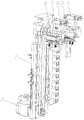
图1是本实用新型的立体结构示意图;Fig. 1 is the three-dimensional structure schematic diagram of the present utility model;

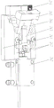
图2是本实用新型另一角度的立体结构示意图;Fig. 2 is the three-dimensional structure schematic diagram of another angle of the present utility model;

图3是本实用新型所述底纸下拉机构的爆炸图;3 is an exploded view of the bottom paper pull-down mechanism of the present invention;

图4是本实用新型所述片料承接机构的立体结构示意图;Fig. 4 is the three-dimensional structure schematic diagram of the sheet material receiving mechanism of the present invention;

图5是本实用新型所述夹纸组件的立体结构示意图;Fig. 5 is the three-dimensional structure schematic diagram of the paper clip assembly of the present invention;

图6是本实用新型所述所述夹纸组件的爆炸图;6 is an exploded view of the paper clip assembly of the present invention;

图7是本实用新型所述放料架和所述底纸回收机构的立体结构示意图;Fig. 7 is the three-dimensional structure schematic diagram of the discharging rack and the bottom paper recycling mechanism of the present invention;

图8是本实用新型所述送纸模块的立体结构示意图;Fig. 8 is the three-dimensional structure schematic diagram of the paper feeding module of the present invention;

图9是本实用新型所述收纸模块的立体结构示意图;Fig. 9 is the three-dimensional structure schematic diagram of the delivery module of the present invention;

图10是本实用新型所述底纸调节机构的立体结构示意图。FIG. 10 is a schematic three-dimensional structure diagram of the bottom paper adjusting mechanism of the present invention.

具体实施方式Detailed ways

如图1至图10所示,在本实施例中,本实用新型包括放料长板1、底纸下拉机构2和片料承接机构3,所述底纸下拉机构2和所述片料承接机构3均设置在所述放料长板1的一侧且相互配合,所述片料承接机构3包括承接座31、承接气缸32和承接台33,所述承接气缸32设置在所述承接座31上,所述承接台33设置在所述承接气缸32的输出端,所述承接台33的上端面与所述放料长板1的上端面平齐,使用时,所述底纸下拉机构2对在放料长板1上的底纸前端进行夹紧并竖直下拉,底纸的前端垂直于所述放料长板1的侧面时,所述承接气缸32驱动,使得所述承接台33将底纸抵在所述放料长板1的侧面,随后底纸在下拉的过程中其上表面的标件将被剥离并移动至所述承接台33上。上述中,所述放料长板1用于底纸的放置,所述底纸下拉机构2用于对底纸进行垂直下拉,所述片料承接机构3用于对剥离的标件进行承接;所述片料承接机构3包括承接座31、承接气缸32和承接台33,所述承接座31设置在所述放料长板1的右侧,所述承接气缸32设置在所述承接座31上用于带动所述承接台33接近或远离所述放料长板1,所述承接台33与所述放料长板1配合并且上端与放料长板1的上端平齐;使用时,所述底纸下拉机构2对在放料长板1上的底纸前端进行夹紧并带动底纸从所述放料长板1的右侧竖直下拉,底纸的前端垂直于所述放料长板1的右侧面时,所述承接气缸32驱动,使得所述承接台33将底纸抵在所述放料长板1的侧面,随后底纸在下拉的过程中其上表面的标件将被剥离并移动至所述承接台33上;另外,所述承接台33上开设有若干个通槽,通槽内设置有标件感应器,能够感应承接台33上是否有标件存在,从而将信息反馈至外部取标件机械手进行标件的取走,使得整体工作更加流畅更加智能。由上述可见,本实用新型整体结构设计合理,采用下拉底纸使得标件由于自身材质的特性而自动剥离,不需要采用吸盘进行吸附拉扯,能够有效避免标件褶皱,从而保证后续工作顺利进行,提高经济效益。As shown in FIGS. 1 to 10 , in this embodiment, the utility model includes a discharge long board 1 , a bottom paper pull-down mechanism 2 and a sheet material receiving mechanism 3 , the bottom paper pull-down mechanism 2 and the sheet material receiving mechanism 3 The mechanisms 3 are all arranged on one side of the discharging long board 1 and cooperate with each other. The sheet material receiving mechanism 3 includes a receiving seat 31, a receiving cylinder 32 and a receiving platform 33, and the receiving cylinder 32 is arranged on the receiving seat. 31, the receiving platform 33 is arranged at the output end of the receiving cylinder 32, and the upper end surface of the receiving platform 33 is flush with the upper end surface of the discharging long board 1. When in use, the bottom paper pull-down mechanism 2. Clamp the front end of the bottom paper on the unloading long board 1 and pull down vertically. When the front end of the bottom paper is perpendicular to the side of the unloading long board 1, the receiving cylinder 32 is driven, so that the receiving platform 33 Press the backing paper against the side of the discharging longboard 1 , and then the labels on the upper surface of the backing paper will be peeled off and moved to the receiving platform 33 during the pulling process of the backing paper. In the above, the discharging long board 1 is used for placing the bottom paper, the bottom paper pull-down mechanism 2 is used for vertically pulling down the bottom paper, and the sheet material receiving mechanism 3 is used for receiving the peeled standard parts; The sheet material receiving mechanism 3 includes a receiving seat 31 , a receiving cylinder 32 and a receiving platform 33 , the receiving seat 31 is arranged on the right side of the discharging long plate 1 , and the receiving cylinder 32 is arranged on the receiving seat 31 The upper part is used to drive the receiving platform 33 close to or away from the discharging long board 1. The receiving platform 33 cooperates with the discharging long board 1 and the upper end is flush with the upper end of the discharging long board 1; when in use, The bottom paper pull-down mechanism 2 clamps the front end of the bottom paper on the discharge long board 1 and drives the bottom paper to vertically pull down from the right side of the discharge long board 1, and the front end of the bottom paper is perpendicular to the bottom paper. When feeding the right side of the longboard 1, the receiving air cylinder 32 is driven, so that the receiving table 33 presses the bottom paper against the side of the discharging longboard 1, and then the bottom paper is pulled down during the process of pulling down. The standard part will be peeled off and moved to the receiving platform 33; in addition, the receiving platform 33 is provided with a plurality of through grooves, and a standard component sensor is arranged in the through groove, which can sense whether there is a standard component on the receiving platform 33. Existence, so that the information is fed back to the external standard picking manipulator to take off the standard parts, making the overall work smoother and more intelligent. It can be seen from the above that the overall structure design of the present utility model is reasonable, and the pull-down bottom paper is used to make the standard part automatically peel off due to the characteristics of its own material, and it is not necessary to use a suction cup for adsorption and pulling, which can effectively avoid the standard part wrinkling, thereby ensuring the smooth progress of the follow-up work, Improve economic efficiency.

如图3所示,在本实施例中,所述底纸下拉机构2包括安装竖板21、驱动电机22、升降台23和两组夹纸组件24,所述升降台23上下滑动设置在所述安装竖板21上,所述驱动电机22设置在所述安装竖板21上并与所述升降台23传动连接,两组所述夹纸组件24设置在所述升降台23的两侧并与所述放料长板1相配合。上述中,所述底纸下拉机构2包括安装竖板21、驱动电机22、升降台23和两组夹纸组件24,所述驱动电机22位于所述安装竖板21的左侧面,所述升降台23位于所述安装侧板的右侧面,所述安装竖板21的右侧面上设置有两根竖直的长导轨,升降台23通过滑块与两根长导轨滑动配合从而取得滑动效果,所述安装竖板21的右侧面的上下端均设置有传动轮,两个所述传动轮通过传动皮带传动连接,所述升降台23与所述传动皮带固定连接,所述驱动电机22的输出轴穿过所述安装竖板21后与位于下端的传动轮连接从而实现与所述升降台23的传动,所述驱动电机22用于带动所述升降台23在所述安装竖板21上上下滑动,从而带动两组所述夹纸组件24进行上下移动,两组所述夹纸组件24用于对放置在所述放料长板1上的底纸进行夹紧;工作时,机械手或人工将片状的底纸放置所述放料长板1上,然后所述驱动电机22驱动带动两组所述夹纸组件24上移,随后两组所述夹纸组件24夹紧底纸的右端的两侧,然后所述驱动电机22反向驱动带动底纸下移,期间所述承接气缸32适时驱动,使得所述承接台33与放料长板1对接,从而令标件从底纸剥离出来并移动至所述承接台33上。As shown in FIG. 3 , in this embodiment, the bottom paper pull-down mechanism 2 includes an installation vertical plate 21 , a drive motor 22 , a lifting platform 23 and two sets of paper clamping assemblies 24 , and the lifting platform 23 is slid up and down to be installed on the On the installation vertical plate 21, the drive motor 22 is arranged on the installation vertical plate 21 and is connected with the lifting platform 23 in a driving manner. It is matched with the discharging long board 1 . In the above, the bottom paper pull-down mechanism 2 includes an installation vertical plate 21, a driving motor 22, a lifting platform 23 and two sets of paper clamping assemblies 24. The driving motor 22 is located on the left side of the installation vertical plate 21. The The lifting platform 23 is located on the right side of the installation side plate, and two vertical long guide rails are arranged on the right side of the installation vertical plate 21. To achieve the sliding effect, the upper and lower ends of the right side of the installation vertical plate 21 are provided with transmission wheels, the two transmission wheels are connected by a transmission belt, and the lifting platform 23 is fixedly connected with the transmission belt. The output shaft of the motor 22 passes through the installation vertical plate 21 and is connected to the transmission wheel located at the lower end to realize the transmission with the lifting platform 23. The driving motor 22 is used to drive the lifting platform 23 on the installation vertical plate. The plate 21 slides up and down, thereby driving the two sets of the paper clip assemblies 24 to move up and down, and the two sets of the paper clip assemblies 24 are used to clamp the bottom paper placed on the discharge long board 1; , the manipulator or manually places the sheet-like bottom paper on the unloading long board 1, and then the drive motor 22 drives the two sets of the paper clip assemblies 24 to move up, and then the two sets of the paper clip assemblies 24 are clamped The two sides of the right end of the bottom paper, and then the driving motor 22 drives the bottom paper to move down, during which the receiving cylinder 32 is driven in a timely manner, so that the receiving platform 33 is docked with the discharge long board 1, so that the standard part It is peeled off from the backing paper and moved to the receiving table 33 .

如图5、图6所示,在本实施例中,所述夹纸组件24包括夹纸底板241、夹纸气缸242、限位推块243、卡位推块244、上夹纸块245、下夹纸块246和两块限位侧板247,所述下夹纸块246和所述夹纸气缸242别设置在所述夹纸底板241的左右两端,两块所述限位侧板247分别设置在所述夹纸底板241的前后两侧,所述限位推块243滑动设置在所述夹纸底板241上,所述卡位推块244的左端设置有第一销轴248,所述第一销轴248的两端分别与开设在两块所述限位侧板247上的弯折腰型孔249相配合,所述卡位推块244的右端开设有铰接槽250,所述限位推块243的左端嵌入所述铰接槽250内并开设有直腰型孔251,所述铰接槽250内设置有穿过所述直腰型孔251的第二销轴252,所述铰接槽250内设置有压缩弹簧253,所述压缩弹簧253的两端与所述卡位推块244及所述限位推块243相配合,所述上夹纸块245设置在所述卡位推块244的左侧并与所述下夹纸块246相配合。上述中,所述夹纸组件24包括夹纸底板241、夹纸气缸242、限位推块243、卡位推块244、上夹纸块245、下夹纸块246和两块限位侧板247,所述夹纸气缸242用于带动所述限位推块243和所述卡位推块244进行配合移动,从而驱动所述上夹纸块245与所述下夹纸块246是否夹紧,所述限位推块243左右滑动设置在所述夹纸底板241上且处在所述下夹纸块246、所述夹纸气缸242和两块所述限位侧板247四者之中,所述卡位推块244位于所述限位推块243的左侧,所述卡位推块244的左端下部通过第一销轴248与两块所述限位侧板247上的所述弯折腰型孔249铰接配合,所述卡位推块244的右端开设有铰接槽250且所述卡位推块244通过第二销轴252与开设在所述限位推块243左端的所述直腰型孔251铰接,所述压缩弹簧253设置在所述铰接槽250内并对所述限位推块243和所述卡位推块244之间形成一个支撑力,所述上夹纸块245和所述下夹纸块246分别设置在所述卡位推块244和所述夹纸底板241的左侧从而能够实现夹紧或松开动作;默认所述夹纸组件24为松开状态,在工作时,所述夹纸气缸242驱动伸出,从而推动所述限位推块243向左滑动,所述压缩弹簧253对所述卡位推块244施压,从而使得所述第二销轴252沿着所述直腰型孔251进行倾斜向上的移动,使得所述卡位推块244的由倾斜状态变为平行状态,与此同时,所述第一销轴248沿着所述弯折腰型孔249进行向下且朝左的移动,以使得原本倾斜打开的所述上夹纸块245改变状态,与所述下夹纸块246平行并配合夹紧;当所述上夹纸块245与所述下夹纸块246夹紧时,由于所述第二销轴252已经处在所述直腰型孔251的最上端,同时所述伸缩弹簧还对所述卡位推块244起到一个支撑力,因此形成自锁,因此使用外力将所述上夹纸块245向上提拉时,所述上夹纸块245能够保持锁死,从而在拉纸的过程中保证对底纸的夹紧。由上述可见,所述夹纸组件24具有自锁功能,能够有效对底纸进行夹紧,即便所述夹纸气缸242在工作过程中出现断气失效的情况,也能够保持对底纸的夹紧,从而保证整个剥离工作的顺利进行。As shown in FIGS. 5 and 6 , in this embodiment, the paper clamping assembly 24 includes a paper clamping bottom plate 241 , a paper clamping cylinder 242 , a limit push block 243 , a card position push block 244 , an upper paper clamp block 245 , The lower paper clamping block 246 and the two limiting side plates 247 are respectively arranged on the left and right ends of the paper clamping bottom plate 241, and the two limiting side plates 247 are respectively arranged on the front and rear sides of the paper clip bottom plate 241, the limit push block 243 is slidably arranged on the paper clip bottom plate 241, and the left end of the card position push block 244 is provided with a first pin 248, The two ends of the first pin shaft 248 are respectively matched with the bending waist-shaped holes 249 formed on the two limiting side plates 247. The left end of the limit push block 243 is embedded in the hinge groove 250 and has a straight waist hole 251 . The hinge groove 250 is provided with a second pin 252 passing through the straight waist hole 251 . A compression spring 253 is arranged in the slot 250. Both ends of the compression spring 253 are matched with the locking push block 244 and the limit push block 243. The upper paper clip block 245 is arranged on the locking push block. The left side of the block 244 and the lower clamping block 246 cooperate. In the above, the paper clip assembly 24 includes a paper clip bottom plate 241, a paper clip cylinder 242, a limit push block 243, a card position push block 244, an upper paper clip block 245, a lower paper clip block 246 and two limit side plates 247. The paper clamping cylinder 242 is used to drive the limit push block 243 and the clamping push block 244 to move together, so as to drive whether the upper paper clamping block 245 and the lower paper clamping block 246 are clamped. , the limit push block 243 is slid left and right on the paper clamping bottom plate 241 and is located in the lower paper clamping block 246, the paper clamping cylinder 242 and the two limit side plates 247. , the locking push block 244 is located on the left side of the limiting push block 243 , and the lower part of the left end of the locking push block 244 passes through the first pin 248 and the two limiting side plates 247 . The bending waist-shaped hole 249 is hingedly matched, the right end of the locking push block 244 is provided with a hinge slot 250, and the locking push block 244 is connected to the left end of the limiting push block 243 through the second pin 252. The straight-waisted hole 251 is hinged, the compression spring 253 is arranged in the hinge groove 250 and forms a supporting force between the limit push block 243 and the card position push block 244, and the upper paper clamping block 245 and the lower paper clamping block 246 are respectively arranged on the left side of the clamping push block 244 and the paper clamping bottom plate 241 so as to be able to clamp or loosen; the paper clamping assembly 24 is in the released state by default. , during operation, the clamping cylinder 242 is driven to extend, thereby pushing the limit push block 243 to slide to the left, and the compression spring 253 presses the clamp push block 244, so that the second push block 244 is pressed. The pin shaft 252 moves obliquely upward along the straight-waisted hole 251, so that the latching push block 244 changes from the inclined state to the parallel state. At the same time, the first pin shaft 248 moves along the The folded waist-shaped hole 249 is moved downward and leftward, so that the upper paper clamping block 245, which was originally opened obliquely, changes state, and is parallel to the lower paper clamping block 246 and clamped together; When the block 245 is clamped with the lower paper clamping block 246, since the second pin 252 is already at the uppermost end of the straight-waisted hole 251, the telescopic spring also pushes the block 244 in place. It acts as a supporting force and thus forms self-locking. Therefore, when the upper paper clamping block 245 is pulled upward by an external force, the upper paper clamping block 245 can be kept locked, so as to ensure the alignment of the bottom paper during the paper pulling process. clamping. It can be seen from the above that the paper clamping assembly 24 has a self-locking function, which can effectively clamp the bottom paper. Even if the paper clamping cylinder 242 fails during the working process, it can maintain the clamping of the bottom paper. , so as to ensure the smooth progress of the entire peeling work.

如图3所示,在本实施例中,所述升降台23上左右滑动设置有安装滑板25,所述升降台23的两侧均设置有同步气缸26,两个所述同步气缸26同步动作且输出端与所述安装滑板25相连,两组所述夹纸组件24设置在所述安装滑板25的两侧。所述安装滑板25通过滑轨和滑块滑动设置在所述升降台23的上端,两个所述同步气功分别位于所述升降台23的两侧且输出端均与所述安装滑板25连接同时两个所述同步气功同步驱动,两组所述夹纸组件24位于所述安装滑板25的两侧因此跟随所述安装滑板25的移动而移动;工作时,两组所述夹纸组件24夹住底纸后在所述驱动电机22的作用下向下拉动,在拉动的过程中,两个所述同步气功驱动带动所述安装滑板25朝所述放料长板1的一侧移动一小段距离,从而使得两组所述夹纸组件24带动底纸跟随移动,而底纸位于所述放料长板1右侧的部位则有竖直状态变为倾斜状态,形成一个负角度,由此一来,可以使得标件更好地从底纸上剥离并进入所述承接台33。由上述可见,通过上述结构,能够大大提升标件从底纸剥离的效果,提高了剥离工作的成功率。As shown in FIG. 3 , in this embodiment, a mounting slide plate 25 is slid left and right on the lifting platform 23 , and synchronizing cylinders 26 are provided on both sides of the lifting platform 23 , and the two synchronizing cylinders 26 act synchronously. The output end is connected to the installation slide 25 , and two sets of the paper clip assemblies 24 are arranged on both sides of the installation slide 25 . The installation slide plate 25 is slidably arranged on the upper end of the lift table 23 through the slide rail and the slider, and the two synchronous qigongs are respectively located on both sides of the lift table 23 and the output ends are connected with the installation slide plate 25 at the same time. The two synchronous qigongs are driven synchronously, and the two sets of paper clip assemblies 24 are located on both sides of the installation slide plate 25, so they move along with the movement of the installation slide plate 25; during operation, the two sets of paper clip assemblies 24 clamp After holding the bottom paper, it is pulled down under the action of the drive motor 22. During the pulling process, the two synchronous qigong drives drive the installation slide plate 25 to move a short section toward the side of the unloading long board 1. distance, so that the two groups of the paper clamping assemblies 24 drive the bottom paper to follow the movement, and the part of the bottom paper located on the right side of the discharge long board 1 has a vertical state and becomes an inclined state, forming a negative angle, thereby As a result, the label can be better peeled off from the backing paper and entered into the receiving table 33 . It can be seen from the above that with the above structure, the effect of peeling off the standard part from the base paper can be greatly improved, and the success rate of peeling work is improved.

如图7所示,在本实施例中,所述片料剥料装置还包括放料架4,所述放料长板1设置在所述放料架4上,所述底纸下拉机构2和所述片料承接机构3均设置在所述放料架4的右侧,所述放料架4的左侧设置有底纸回收机构5,所述底纸回收机构5包括相配合的送纸模块51和收纸模块52,所述收纸模块52包括固定架521、升降气缸522、升降架523、收纸电机524和收纸滚筒525,所述固定架521设置在所述放料架4上,所述升降气缸522设置在所述固定架521上,所述升降架523设置在所述升降气缸522的输出端,所述收纸滚筒525转动设置在所述升降架523上并与所述放料长板1相配合,所述收纸电机524设置在所述升降架523上并与所述收纸滚筒525传动连接。上述中,本实用新型还包括放料架4和底纸回收机构5,所述放料长板1设置在所述放料架4的上端,所述底纸下拉机构2和所述片料承接机构3位于所述放料架4的右侧,所述底纸回收机构5用于对取完标件的底纸进行回收,从而集中处理,所述底纸回收机构5包括送纸模块51和收纸模块52两个模块,所述送纸模块51对取完标件的底纸进行拉回,从而使得底纸能够被收纸模块52回收;收纸模块52包括固定架521、升降装置、升降架523、收纸电机524和收纸滚筒525,收纸时,送纸模块51将底纸移动至送纸模块51的工作位置上,升降装置带动升降架523下移,使得收纸滚筒525抵住底纸,然后收纸电机524驱动,收纸滚筒525转动带动底纸朝所述放料长板1的左端移动,从而实现将底纸进行送料。由上述可见,所述底纸回收机构5通过送纸模块51和送纸模块51的配合能够实现对片状底纸的回收,适用于片状底纸回收,能够持续不间断作业,工作效率高。另外,在本实施例中,所述收纸滚筒525的数量为两个,两个所述收纸滚筒525平行设置在所述升降架523的下端,所述升降架523的外侧转动设置有两个同步大齿轮,两个所述同步大齿轮上设置有同步平皮带,所述收纸电机524与其中一个所述同步大齿轮传动连接,所述升降架523的外侧转动设置有两个同步小齿轮,两个所述同步小齿轮分别与两个所述同步大齿轮相啮合并与相应的所述收纸滚筒525相连接。所述收纸滚筒525共有两个,沿所述放料长板1的方向一前一后设置在所述升降架523内,两个所述同步大齿轮通过所述同步平皮带实现连接,而所述收纸电机524与其中一个所述同步大齿轮连接从而可以带动两个所述同步大齿轮同步转动,两个所述收纸滚筒525的中心轴的同一端均穿出所述升降架,两个所述同步小齿轮分别设置在两根中心轴上,因此两个所述同步小齿轮的转动与所述收纸滚筒525的转动一致,而两个所述同步小齿轮又分别与相应的所述同步大齿轮啮合,因此当所述收纸电机524驱动时,两个所述收纸滚筒525能够同时转动,在进行底纸回收时,能够对长度较长的底纸进行回收,保证底纸成功送出。As shown in FIG. 7 , in this embodiment, the sheet material stripping device further includes a feeding rack 4 on which the feeding long board 1 is arranged, and the bottom paper pull-down mechanism 2 and the sheet material receiving mechanism 3 are both arranged on the right side of the unloading rack 4, the left side of the unloading rack 4 is provided with a bottom paper recovery mechanism 5, and the bottom paper recovery mechanism 5 includes a matching feeder. A paper module 51 and a paper delivery module 52, the paper delivery module 52 includes a fixed frame 521, a lifting cylinder 522, a lifting frame 523, a paper delivery motor 524 and a paper delivery cylinder 525, and the fixed frame 521 is arranged on the unloading frame 4, the lifting cylinder 522 is arranged on the fixing frame 521, the lifting frame 523 is arranged at the output end of the lifting cylinder 522, and the delivery cylinder 525 is rotatably arranged on the lifting frame 523 and is connected with the lifting frame 523. The unwinding long board 1 is matched, and the delivery motor 524 is arranged on the lifting frame 523 and is connected with the delivery cylinder 525 in a driving manner. In the above, the present invention also includes a discharging rack 4 and a bottom paper recovery mechanism 5, the discharging long board 1 is arranged on the upper end of the discharging rack 4, and the bottom paper pulling mechanism 2 and the sheet material undertake The mechanism 3 is located on the right side of the unloading rack 4. The bottom paper recovery mechanism 5 is used to recover the bottom paper after the standard parts are taken out, so as to be processed centrally. The bottom paper recovery mechanism 5 includes a paper feeding module 51 and The paper delivery module 52 has two modules. The paper feed module 51 pulls back the bottom paper after taking the standard parts, so that the bottom paper can be recovered by the paper delivery module 52; the paper delivery module 52 includes a fixing frame 521, a lifting device, The lifting frame 523, the paper delivery motor 524 and the delivery roller 525. When the paper is delivered, the paper feeding module 51 moves the bottom paper to the working position of the paper feeding module 51, and the lifting device drives the lifting frame 523 to move down, so that the delivery roller 525 The bottom paper is pressed against the bottom paper, and then the delivery motor 524 is driven, and the delivery roller 525 rotates to drive the bottom paper to move toward the left end of the unloading longboard 1, thereby realizing the feeding of the bottom paper. It can be seen from the above that the bottom paper recovery mechanism 5 can realize the recovery of the sheet bottom paper through the cooperation of the paper feeding module 51 and the paper feeding module 51, is suitable for the recovery of the sheet bottom paper, can continuously operate without interruption, and has high work efficiency . In addition, in this embodiment, the number of the delivery rollers 525 is two, the two delivery rollers 525 are arranged in parallel at the lower end of the lifting frame 523, and the outer side of the lifting frame 523 is rotatably provided with two There are two synchronous large gears, two synchronous large gears are provided with synchronous flat belts, the delivery motor 524 is drivingly connected with one of the synchronous large gears, and the outer side of the lifting frame 523 is rotated with two synchronous small The two synchronous pinions mesh with the two synchronous large gears respectively and are connected with the corresponding paper delivery drum 525 . There are two delivery rollers 525, which are arranged in the lifting frame 523 one after the other along the direction of the discharging long board 1. The two synchronous large gears are connected by the synchronous flat belt, and the The delivery motor 524 is connected with one of the synchronous large gears so as to drive the two synchronous large gears to rotate synchronously. The two synchronizing pinions are respectively arranged on the two central shafts, so the rotation of the two synchronizing pinions is consistent with the rotation of the delivery drum 525, and the two synchronizing pinions are respectively connected with the corresponding The large synchronous gears are meshed, so when the delivery motor 524 is driven, the two delivery drums 525 can rotate at the same time. When the bottom paper is recovered, the long bottom paper can be recovered to ensure the bottom paper. The paper was sent successfully.

如图7、图8所示,在本实施例中,所述送纸模块51包括送纸电机511、滑动板512和两组拉纸组件513,所述送纸电机511设置在所述放料架4内,所述滑动板512滑动设置在所述放料架4上且位于所述放料长板1的下方,两组所述拉纸组件513分别设置在所述滑动板512的两侧,所述放料长板1位于两个所述拉纸组件513之间,所述送纸电机511的输出轴穿出所述放料架4并设置有连接齿轮514,所述放料架4靠近所述连接齿轮514的一侧且远离所述连接齿轮514的一端转动设置有配合齿轮515,所述配合齿轮515与所述连接齿轮514通过连接皮带516传动连接,所述滑动板512的一端与所述连接皮带516连接。上述中,所述送纸电机511设置在所述放料架4的内部,所述滑动板512通过两根滑轨和两块滑块之间的配合滑动设置在所述放料架4上并且所述滑动板512处在所述滑动板512的下方,两个所述拉纸组件513位于所述滑动板512的两端,所述拉纸组件513可为夹爪用于对放置在所述承载长板上的底纸的两侧进行夹紧,所述送纸电机511的输出轴穿过所述放料架4并固定设置有连接齿轮514,所述连接齿轮514通过连接皮带516与所述配合齿轮515连接,所述配合齿轮515和所述连接齿轮514分别处在所述放料架4的两端,而所述滑动板512的一端与所述连接皮带516连接,因此当所述送纸电机511驱动时,所述连接皮带516移动从而带动所述滑动板512在所述放料架4上进行滑动,从而可以使得所述拉纸组件513可以带动底纸进行移动,由此可实现送纸动作;所述拉纸组件513结构与所述夹纸组件24相似,工作原理相同。另外,需要说明的是,所述送纸模块51还能对底纸起到拉紧作用,在所述底纸下拉机构2对底纸进行下拉时,所述拉纸组件513将底纸的左端进行夹紧,当所述底纸下拉机构2下拉时,所述送纸电机511断使能,从而对底纸形成一个拉紧力但又不妨碍底纸移动,从而使得底纸能够紧贴所述放料长板1,由此保证标件能够顺利剥离。As shown in FIG. 7 and FIG. 8 , in this embodiment, the paper feeding module 51 includes a paper feeding motor 511 , a sliding plate 512 and two sets of paper pulling assemblies 513 . In the rack 4 , the sliding plate 512 is slidably arranged on the discharging rack 4 and is located below the discharging long plate 1 , and two sets of the paper pulling assemblies 513 are respectively arranged on both sides of the sliding plate 512 , the feeding long board 1 is located between the two paper pulling assemblies 513, the output shaft of the feeding motor 511 passes through the feeding frame 4 and is provided with a connecting gear 514, the feeding frame 4 A matching gear 515 is rotatably disposed on the side close to the connecting gear 514 and away from the connecting gear 514 . Connect with the connecting belt 516 . In the above, the paper feeding motor 511 is arranged inside the unloading rack 4, and the sliding plate 512 is slidably arranged on the unloading rack 4 through the cooperation between the two sliding rails and the two sliders. The sliding plate 512 is located below the sliding plate 512, and the two paper pulling assemblies 513 are located at both ends of the sliding plate 512. The two sides of the bottom paper on the carrying long board are clamped. The output shaft of the paper feeding motor 511 passes through the unloading rack 4 and is fixedly provided with a connecting gear 514. The connecting gear 514 is connected to the The matching gear 515 is connected, the matching gear 515 and the connecting gear 514 are located at two ends of the discharging rack 4 respectively, and one end of the sliding plate 512 is connected with the connecting belt 516, so when the When the paper feeding motor 511 is driven, the connecting belt 516 moves to drive the sliding plate 512 to slide on the unloading rack 4, so that the paper pulling assembly 513 can drive the bottom paper to move. The paper feeding action is realized; the structure of the paper pulling component 513 is similar to the paper clamping component 24, and the working principle is the same. In addition, it should be noted that the paper feeding module 51 can also play a role in tensioning the bottom paper. When the bottom paper pull-down mechanism 2 pulls down the bottom paper, the paper pulling component 513 pulls the left end of the bottom paper. When the bottom paper pull-down mechanism 2 is pulled down, the paper feeding motor 511 is turned off, so as to form a tension force on the bottom paper without hindering the movement of the bottom paper, so that the bottom paper can be tightly attached to the bottom paper. The discharge long board 1 is described, thereby ensuring that the standard parts can be peeled off smoothly.

如图10所示,在本实施例中,所述片料剥料装置还包括底纸调节机构6,所述底纸调节机构6包括第一气缸61、平行气缸62和两块调位板63,所述第一气缸61竖直设置且位于所述放料长板1的下方,所述平行气缸62设置在所述第一气缸61的输出端,两块所述调位板63分别设置所述平行气缸62的两个输出端上,两块所述调位板63位于所述放料长板1的两侧,两块所述调位板63的内侧均设置有调节阶梯64。上述中,所述底纸调节机构6设置在所述放料架4内的右端,所述底纸调节机构6包括第一气缸61、平行气缸62和两块调位板63,所述第一气缸61位于所述放料长板1的下方并且竖直设置,所述第一气缸61用于带动所述平行气缸62进行上下移动,所述平行气缸62水平设置且用于带动两块所述调位板63进行开合动作,两块所述调位板63的相对内侧均设有调节阶梯64,所述调节阶梯64用于对片状底纸进行调节;工作时,人工或机械手将片状底纸放置在所述放料长板1上,然后所述第一气缸61驱动所述平行气缸62上移,使得两块所述调节板位于底纸的两侧,然后所述平行气缸62驱动,两块所述调位板63相对靠近,使得底纸的两侧分别被两道所述调节阶梯64承载,然后所述平行气缸62继续驱动,使得底纸的两侧与所述调位板63的内侧面平齐,从而达到调位作用。由上述可见,通过 所述底纸调节机构6,可以在进行标件剥离工作前先进行定位工作,从而使得底纸能够按照理想状态被所述底纸下拉机构2带动,从而更好进行剥离工作。As shown in FIG. 10 , in this embodiment, the sheet material peeling device further includes a bottom paper adjusting mechanism 6 , and the bottom paper adjusting mechanism 6 includes a first air cylinder 61 , a parallel air cylinder 62 and two positioning plates 63 , the first cylinder 61 is arranged vertically and is located below the discharge long plate 1 , the parallel cylinder 62 is arranged at the output end of the first cylinder 61 , and the two positioning plates 63 are respectively arranged at the On the two output ends of the parallel cylinder 62 , the two adjusting plates 63 are located on both sides of the discharging long plate 1 , and the inner sides of the two adjusting plates 63 are provided with adjusting steps 64 . In the above, the bottom paper adjusting mechanism 6 is arranged at the right end of the discharging rack 4, and the bottom paper adjusting mechanism 6 includes a first air cylinder 61, a parallel air cylinder 62 and two positioning plates 63. The air cylinder 61 is located below the discharging long plate 1 and is arranged vertically. The first air cylinder 61 is used to drive the parallel air cylinder 62 to move up and down. The parallel air cylinder 62 is arranged horizontally and used to drive the two The position adjustment plates 63 are opened and closed, and two adjustment steps 64 are provided on the opposite inner sides of the two position adjustment plates 63. The adjustment steps 64 are used to adjust the sheet bottom paper; Then the first air cylinder 61 drives the parallel air cylinder 62 to move up, so that the two adjusting plates are located on both sides of the base paper, and then the parallel air cylinder 62 Drive, the two adjusting plates 63 are relatively close to each other, so that the two sides of the bottom paper are respectively carried by the two adjusting steps 64, and then the parallel cylinder 62 continues to drive, so that the two sides of the bottom paper are in line with the adjusting steps 64. The inner side of the plate 63 is flush, so as to achieve the function of adjusting the position. It can be seen from the above that through the bottom paper adjusting mechanism 6, the positioning work can be performed before the standard part peeling work, so that the bottom paper can be driven by the bottom paper pull-down mechanism 2 in an ideal state, so as to better perform the peeling work. .

如图8所示,在本实施例中,所述放料架4的左侧设置有吹纸风机7,所述吹纸风机7位于所述收纸滚筒525的下方并与所述收纸滚筒525相配合,所述放料长板1的左右两端均开设有安装槽,所述安装槽内设置有底纸感应器。所述吹纸风机7用于与所述收纸模块52相配合,放置废弃的底纸挂在所述放料长板1上而没掉落至指定位置,保证废弃底纸的完全回收;两个所述底纸感应器均用于感应所述放料长板1上有无底纸,其中,左端的所述底纸感应器用于感应是否有废弃的底纸没有掉落,从而控制所述吹纸风机7进行工作,右端的所述底纸感应器用于感应所述放料长板1上是否有底纸,从而将信息反馈至所述底纸下拉机构2或所述底纸回收机构5,从而进行相应的工作。As shown in FIG. 8 , in this embodiment, a paper blower 7 is provided on the left side of the unloading rack 4 , and the paper blower 7 is located below the delivery drum 525 and is connected with the delivery drum 525, the left and right ends of the discharge long board 1 are provided with installation grooves, and a bottom paper sensor is arranged in the installation grooves. The paper blowing fan 7 is used to cooperate with the delivery module 52 to place the discarded bottom paper on the unloading longboard 1 without falling to the designated position, so as to ensure the complete recovery of the discarded bottom paper; two Each of the backing paper sensors is used to sense whether there is backing paper on the discharge long board 1, wherein the backing paper sensor at the left end is used to sense whether there is discarded backing paper that has not fallen, so as to control the The paper blower 7 is working, and the bottom paper sensor on the right end is used to sense whether there is bottom paper on the discharging longboard 1, so as to feed back the information to the bottom paper pull-down mechanism 2 or the bottom paper recovery mechanism 5 , so as to carry out the corresponding work.

如图4所示,在本实施例中,所述承接座31上设置有竖直气缸34,所述承接气缸32设置在所述竖直气缸34的输出端。所述竖直气缸34用于带动所述承接气缸32进行上下移动,从而实现所述承接台33的高度调节,以便于更好地与所述放料长板1配合,增强适应能力。As shown in FIG. 4 , in this embodiment, a vertical cylinder 34 is disposed on the receiving seat 31 , and the receiving cylinder 32 is disposed at the output end of the vertical cylinder 34 . The vertical cylinder 34 is used to drive the receiving cylinder 32 to move up and down, so as to realize the height adjustment of the receiving platform 33, so as to better cooperate with the discharging long board 1 and enhance the adaptability.

如图4所示,在本实施例中,所述承接座31靠近所述放料长板1的一侧的上端面设置有锯齿纹35,所述锯齿纹35上涂设有铁氟龙涂层。所述承接座31的上端面设置锯齿纹35能够降低标件与所述承接座31的粘合,从而更好地将标件取走,并且通过所述铁氟龙涂层,能够进一步降低标件的粘合效果。As shown in FIG. 4 , in this embodiment, the upper end surface of the side of the receiving seat 31 close to the discharging long plate 1 is provided with a zigzag pattern 35 , and the zigzag pattern 35 is coated with Teflon coating Floor. The zigzag pattern 35 on the upper end surface of the receiving seat 31 can reduce the adhesion between the target and the receiving seat 31, so as to better remove the target, and through the Teflon coating, the standard can be further reduced. The bonding effect of the pieces.

本实用新型的工作原理是:人工或机械手将片状底纸放置在所述放料长板1上,随后所述底纸调节机构6动作对底纸进行调位,所述底纸下拉机构2将底纸的右端两侧夹紧并且带动底纸下拉,同时所述片料承接机构3动作与放料长板1对接,所述底纸回收机构5的送纸模块51夹住底纸的左端两侧,从而对底纸形成一个拉力,使得底纸能紧贴所述放料长板1,底纸在下拉的过程中,由于底纸由平行状态变为竖直状态,再与所述片料承接机构3配合,因此底纸上的标件将被剥离并移动至片料承接机构3上,然后由贴标机械手取走标件进行贴标;当底纸上的标件全部剥离后,所述底纸下拉机构2松开底纸并复位,送纸模块51将底纸拉回并送至所述收纸模块52的工作位置处,由收纸模块52对废弃的底纸进行回收,一次剥离工作完成;重复上述动作即可实现循环作业。The working principle of the present utility model is as follows: manually or mechanically, place the sheet-like bottom paper on the discharging long board 1, then the bottom paper adjusting mechanism 6 acts to adjust the position of the bottom paper, and the bottom paper pulling mechanism 2 adjusts the position of the bottom paper. Clamp the two sides of the right end of the bottom paper and drive the bottom paper to pull down. At the same time, the sheet receiving mechanism 3 moves to butt the discharge longboard 1, and the paper feeding module 51 of the bottom paper recovery mechanism 5 clamps the left end of the bottom paper. two sides, thereby forming a pulling force on the bottom paper, so that the bottom paper can be close to the discharging longboard 1. During the process of pulling down the bottom paper, since the bottom paper is changed from a parallel state to a vertical state, it is further connected with the sheet The material receiving mechanism 3 cooperates, so the label on the backing paper will be peeled off and moved to the sheet material receiving mechanism 3, and then the labeling robot will take away the label for labeling; when the label on the backing paper is all peeled off, The bottom paper pull-down mechanism 2 loosens the bottom paper and resets, and the paper feeding module 51 pulls back the bottom paper and sends it to the working position of the paper delivery module 52, and the discarded bottom paper is recovered by the paper delivery module 52. The peeling work is completed once; repeating the above actions can realize the cycle operation.

虽然本实用新型的实施例是以实际方案来描述的,但是并不构成对本实用新型含义的限制,对于本领域的技术人员,根据本说明书对其实施方案的修改及与其他方案的组合都是显而易见的。Although the embodiments of the present utility model are described with actual solutions, they do not constitute a limitation on the meaning of the present utility model. For those skilled in the art, modifications to the embodiments according to the present specification and combinations with other schemes are all Obvious.

Claims (10)

1. The utility model provides a sheet material stripping device which characterized in that: the device comprises a discharging long plate (1), a bottom paper pull-down mechanism (2) and a sheet material bearing mechanism (3), wherein the bottom paper pull-down mechanism (2) and the sheet material bearing mechanism (3) are arranged on one side of the discharging long plate (1) and are matched with each other, the sheet material bearing mechanism (3) comprises a bearing seat (31), a bearing cylinder (32) and a bearing table (33), the bearing cylinder (32) is arranged on the bearing seat (31), the bearing table (33) is arranged at the output end of the bearing cylinder (32), the upper end face of the bearing table (33) is flush with the upper end face of the discharging long plate (1), when the device is used, the bottom paper pull-down mechanism (2) clamps and vertically pulls down the front end of bottom paper on the discharging long plate (1), and when the front end of the bottom paper is perpendicular to the side face of the discharging long plate (1), the bearing cylinder (32) is driven, so that the receiving platform (33) supports the bottom paper on the side surface of the discharging long plate (1), and then the standard part on the upper surface of the bottom paper is peeled off and moved onto the receiving platform (33) in the process of pulling down the bottom paper.
2. A sheet stripping apparatus as claimed in claim 1, wherein: bottom paper pull-down mechanism (2) are including installation riser (21), driving motor (22), elevating platform (23) and two sets of paper components (24) of pressing from both sides, the setting of sliding from top to bottom of elevating platform (23) is in on installation riser (21), driving motor (22) set up on installation riser (21) and with elevating platform (23) transmission is connected, and is two sets of paper components (24) of pressing from both sides set up elevating platform (23) the both sides and with blowing long slab (1) cooperatees.
3. A sheet stripping apparatus as claimed in claim 2, wherein: the paper clamping assembly (24) comprises a paper clamping bottom plate (241), a paper clamping cylinder (242), a limiting push block (243), a clamping push block (244), an upper paper clamping block (245), a lower paper clamping block (246) and two limiting side plates (247), the lower paper clamping block (246) and the paper clamping cylinder (242) are respectively arranged at the left end and the right end of the paper clamping bottom plate (241), the two limiting side plates (247) are respectively arranged at the front side and the rear side of the paper clamping bottom plate (241), the limiting push block (243) is slidably arranged on the paper clamping bottom plate (241), a first pin shaft (248) is arranged at the left end of the clamping push block (244), two ends of the first pin shaft (248) are respectively matched with bent waist-shaped holes (249) formed in the two limiting side plates (247), a hinge groove (250) is formed at the right end of the clamping push block (244), and the left end of the limiting push block (250) is embedded into the hinge groove (250) and provided with a straight waist-shaped hole (251), a second pin shaft (252) penetrating through the straight waist-shaped hole (251) is arranged in the hinge groove (250), a compression spring (253) is arranged in the hinge groove (250), two ends of the compression spring (253) are matched with the clamping push block (244) and the limiting push block (243), and the upper paper clamping block (245) is arranged on the left side of the clamping push block (244) and matched with the lower paper clamping block (246).
4. A sheet stripping apparatus as claimed in claim 2, wherein: the paper clamping device is characterized in that an installation sliding plate (25) is arranged on the lifting platform (23) in a sliding mode from left to right, synchronous cylinders (26) are arranged on the two sides of the lifting platform (23) respectively, the synchronous cylinders (26) act synchronously, the output end of the synchronous cylinders is connected with the installation sliding plate (25), and the paper clamping assemblies (24) are arranged on the two sides of the installation sliding plate (25).
5. A sheet stripping apparatus as claimed in claim 1, wherein: the paper feeding device is characterized by further comprising a material feeding frame (4), wherein the material feeding long plate (1) is arranged on the material feeding frame (4), the bottom paper pull-down mechanism (2) and the sheet material bearing mechanism (3) are arranged on the right side of the material feeding frame (4), a bottom paper recovery mechanism (5) is arranged on the left side of the material feeding frame (4), the bottom paper recovery mechanism (5) comprises a paper feeding module (51) and a paper collecting module (52) which are matched with each other, the paper collecting module (52) comprises a fixing frame (521), a lifting cylinder (522), a lifting frame (523), a paper collecting motor (524) and a paper collecting roller (525), the fixing frame (521) is arranged on the material feeding frame (4), the lifting cylinder (522) is arranged on the fixing frame (521), the lifting frame (523) is arranged at the output end of the lifting cylinder (522), the paper collecting roller (525) is rotatably arranged on the lifting frame (523) and matched with the material feeding long plate (1), the delivery motor (524) is arranged on the lifting frame (523) and is in transmission connection with the delivery roller (525).
6. A sheet stripping apparatus as claimed in claim 5, wherein: the paper feeding module (51) comprises a paper feeding motor (511), a sliding plate (512) and two groups of paper pulling components (513), the paper feeding motor (511) is arranged in the material placing frame (4), the sliding plate (512) is arranged on the material placing frame (4) in a sliding mode and located below the material placing long plate (1), the two groups of paper pulling components (513) are arranged on two sides of the sliding plate (512) respectively, the material placing long plate (1) is located between the two paper pulling components (513), an output shaft of the paper feeding motor (511) penetrates out of the material placing frame (4) and is provided with a connecting gear (514), a matching gear (515) is rotatably arranged at one end, close to one side of the connecting gear (514), far away from the connecting gear (514), of the matching gear (515) and the connecting gear (514) are in transmission connection through a connecting belt (516), one end of the sliding plate (512) is connected with the connecting belt (516).
7. A sheet stripping apparatus as claimed in claim 1, wherein: it still includes base stock adjustment mechanism (6), base stock adjustment mechanism (6) include first cylinder (61), parallel cylinder (62) and two positioning plate (63), first cylinder (61) vertical setting just is located the below of blowing long slab (1), parallel cylinder (62) set up the output of first cylinder (61), two positioning plate (63) set up respectively on two output of parallel cylinder (62), two positioning plate (63) are located the both sides of blowing long slab (1), two the inboard of positioning plate (63) all is provided with adjusts ladder (64).
8. A sheet stripping apparatus as claimed in claim 5, wherein: the paper blowing machine is characterized in that a paper blowing fan (7) is arranged on the left side of the discharging frame (4), the paper blowing fan (7) is located below the paper collecting roller (525) and matched with the paper collecting roller (525), mounting grooves are formed in the left end and the right end of the discharging long plate (1), and bottom paper inductors are arranged in the mounting grooves.
9. A sheet stripping apparatus as claimed in claim 1, wherein: the bearing seat (31) is provided with a vertical cylinder (34), and the bearing cylinder (32) is arranged at the output end of the vertical cylinder (34).
10. A sheet stripping apparatus as claimed in claim 1, wherein: the upper end face of one side, close to the discharge long plate (1), of the bearing seat (31) is provided with sawtooth grains (35), and a Teflon coating is coated on the sawtooth grains (35).
CN202122825688.5U 2021-11-18 2021-11-18 Sheet stripping device Withdrawn - After Issue CN217436289U (en)

Priority Applications (1)

Application Number Priority Date Filing Date Title
CN202122825688.5U CN217436289U (en) 2021-11-18 2021-11-18 Sheet stripping device

Applications Claiming Priority (1)

Application Number Priority Date Filing Date Title
CN202122825688.5U CN217436289U (en) 2021-11-18 2021-11-18 Sheet stripping device

Publications (1)

Publication Number Publication Date
CN217436289U true CN217436289U (en) 2022-09-16

Family

ID=83208789

Family Applications (1)

Application Number Title Priority Date Filing Date
CN202122825688.5U Withdrawn - After Issue CN217436289U (en) 2021-11-18 2021-11-18 Sheet stripping device

Country Status (1)

Country Link
CN (1) CN217436289U (en)

Cited By (2)

* Cited by examiner, † Cited by third party
Publication number Priority date Publication date Assignee Title
CN113978874A (en) * 2021-11-18 2022-01-28 珠海博杰电子股份有限公司 Sheet stripping device
CN120440609A (en) * 2025-07-14 2025-08-08 深圳一苇科技有限公司 A compact sheet feeder

Cited By (3)

* Cited by examiner, † Cited by third party
Publication number Priority date Publication date Assignee Title
CN113978874A (en) * 2021-11-18 2022-01-28 珠海博杰电子股份有限公司 Sheet stripping device
CN113978874B (en) * 2021-11-18 2025-07-08 珠海博杰电子股份有限公司 Sheet stripping device
CN120440609A (en) * 2025-07-14 2025-08-08 深圳一苇科技有限公司 A compact sheet feeder

Similar Documents

Publication Publication Date Title
CN205082067U (en) Peeling device
WO2018126918A1 (en) Bonding machine for new and old smt splice tapes
CN213936123U (en) Automatic adhesive tape pasting machine for sheet products
CN114725475B (en) Fidek rubberizing equipment
CN110416593B (en) Rubberizing device
CN111137679A (en) An automatic film sticking and two-dimensional code equipment
CN211195251U (en) Full-automatic net cage laminating machine
CN209633979U (en) An automatic soft-to-soft flexible laminating machine
CN210083641U (en) Film sticking machine for FPC flexible board
CN205185494U (en) Film tearing device
CN115610789A (en) From type membrane dyestripping device
CN114093267A (en) A fully automatic special-shaped polarizer laminating machine and laminating process thereof
CN112571917A (en) Glass feeding method and device for backlight assembly
CN209920618U (en) Full-automatic shaping card pasting machine
CN118888485B (en) Photovoltaic double-glass module frame removal and tape removal device and method
CN113978874B (en) Sheet stripping device
CN110342043B (en) Labeling method for automatic disc changer
CN211893994U (en) A film sticking device
CN210777620U (en) Full-automatic flexible screen body laminating machine
CN221774700U (en) An automated device for transferring and collecting conductive fabrics
KR100638114B1 (en) Laminating device
CN219960962U (en) A kind of roll material FPC laminating machine
CN113290837A (en) Automatic pad pasting device of digital product
CN210477830U (en) A keyboard hot melt film integrated equipment
CN116224635B (en) A display screen adhesive tape processing production line

Legal Events

Date Code Title Description
GR01 Patent grant
GR01 Patent grant
AV01 Patent right actively abandoned

Granted publication date: 20220916

Effective date of abandoning: 20250708

AV01 Patent right actively abandoned

Granted publication date: 20220916

Effective date of abandoning: 20250708