CN217433379U - Double-station laser cutting machine - Google Patents
Double-station laser cutting machine Download PDFInfo
- Publication number
- CN217433379U CN217433379U CN202221077905.5U CN202221077905U CN217433379U CN 217433379 U CN217433379 U CN 217433379U CN 202221077905 U CN202221077905 U CN 202221077905U CN 217433379 U CN217433379 U CN 217433379U
- Authority
- CN
- China
- Prior art keywords
- axis
- laser cutting
- air cylinder
- axis linear
- rotating chuck
- Prior art date
- Legal status (The legal status is an assumption and is not a legal conclusion. Google has not performed a legal analysis and makes no representation as to the accuracy of the status listed.)
- Expired - Fee Related
Links
Images
Classifications
-
- Y—GENERAL TAGGING OF NEW TECHNOLOGICAL DEVELOPMENTS; GENERAL TAGGING OF CROSS-SECTIONAL TECHNOLOGIES SPANNING OVER SEVERAL SECTIONS OF THE IPC; TECHNICAL SUBJECTS COVERED BY FORMER USPC CROSS-REFERENCE ART COLLECTIONS [XRACs] AND DIGESTS
- Y02—TECHNOLOGIES OR APPLICATIONS FOR MITIGATION OR ADAPTATION AGAINST CLIMATE CHANGE
- Y02P—CLIMATE CHANGE MITIGATION TECHNOLOGIES IN THE PRODUCTION OR PROCESSING OF GOODS
- Y02P70/00—Climate change mitigation technologies in the production process for final industrial or consumer products
- Y02P70/10—Greenhouse gas [GHG] capture, material saving, heat recovery or other energy efficient measures, e.g. motor control, characterised by manufacturing processes, e.g. for rolling metal or metal working
Landscapes
- Laser Beam Processing (AREA)
Abstract
The utility model relates to the technical field of laser cutting, in particular to a double-station laser cutting machine, which comprises a frame platform, a cutting support seat arranged on the frame platform, a Y-axis module arranged on the cutting support seat, a Z-axis module connected with the Y-axis module, and a laser cutting head connected with the Z-axis module, wherein a workpiece fixing device is arranged below the laser cutting head; the workpiece fixing device comprises a left air cylinder, a right air cylinder, a left rotating chuck and a right rotating chuck which are fixed on the rack platform, an air cylinder rod of the left air cylinder is connected with the left rotating chuck, and an air cylinder rod of the right air cylinder is connected with the right rotating chuck. This two laser cutting machine is under the prerequisite that does not additionally increase more space, through the reciprocal cutting of two processing positions, and unloading time in the saving has promoted cutting efficiency greatly.
Description
Technical Field
The utility model relates to a laser cutting technical field, concretely relates to duplex position laser cutting machine.
Background
The existing cutting of the tube, the lampshade and the plate is mainly completed by laser cutting, wherein the laser cutting is to heat a workpiece by using a laser beam with high energy density so as to quickly rise the temperature, and the temperature reaches the boiling point of the material in a very short time so as to vaporize the material to form steam, the steam is sprayed out at a very high speed, and a notch is formed on the material while the steam is sprayed out. Because the laser cutting tool has high efficiency, neat cutting surface and convenient later processing and use, the laser cutting machine has very wide application in the cutting processing of various pipes and the like.
When a laser cutting machine on the market cuts a single product part of a non-whole pipe, after the machining of one product is completed, the part which is cut by a worker needs to be taken off, and then a new part to be cut is mounted, so that the time consumed in the process of loading and unloading is long every time, the equipment utilization rate is low, and the requirement of large-scale production cannot be met.
Disclosure of Invention
An object of the utility model is to prior art not enough, and provide a compact structure's duplex position laser cutting machine, this duplex position laser cutting machine is under the prerequisite that does not additionally increase more space, through two reciprocal cutting in processing position, and unloading time on the saving has promoted cutting efficiency greatly.
The purpose of the utility model is realized through the following technical scheme:
the double-station laser cutting machine comprises a rack platform, a cutting support seat arranged on the rack platform, a Y-axis linear module arranged on the cutting support seat, a Z-axis linear module connected with the Y-axis linear module, and a laser cutting head connected with the Z-axis linear module, wherein a workpiece fixing device is arranged below the laser cutting head;
the workpiece fixing device comprises a left air cylinder, a right air cylinder, a left rotating chuck and a right rotating chuck which are fixed on the rack platform, wherein an air cylinder rod of the left air cylinder is connected with the left rotating chuck, and an air cylinder rod of the right air cylinder is connected with the right rotating chuck;
and waste collecting grooves are formed below the left rotary chuck and the right rotary chuck.
In the technical scheme, the Y-axis linear module comprises a Y-axis linear guide rail arranged on the cutting support seat, a Y-axis sliding block connected with the Y-axis linear guide rail and a Y-axis motor driving box fixed on the Y-axis sliding block, and a Y-axis servo motor is arranged in the Y-axis motor driving box.
In the above technical scheme, the Z axis linear module comprises a Z axis linear guide fixed on the Y axis motor driving box, a Z axis servo motor, a lead screw connected with the Z axis servo motor, and a lifting slide plate connected with the lead screw, wherein a Z axis slide block is arranged on the Z axis linear guide, and the lifting slide plate is connected with the Z axis slide block.
In the technical scheme, the laser cutting head is connected with the lifting sliding plate through the mounting seat.
In the technical scheme, the left rotating chuck and the right rotating chuck are both provided with clamping parts, and clamping grooves for inserting workpieces are formed in the clamping parts.
In the technical scheme, the bottom of the waste collecting tank is an inclined surface which is inclined downwards.
The utility model has the advantages that:
the utility model discloses a double-station laser cutting machine, which comprises a frame platform, a cutting support seat arranged on the frame platform, a Y-axis module arranged on the cutting support seat, a Z-axis module connected with the Y-axis module, and a laser cutting head connected with the Z-axis module, wherein a workpiece fixing device is arranged below the laser cutting head; the workpiece fixing device comprises a left air cylinder, a right air cylinder, a left rotating chuck and a right rotating chuck which are fixed on the rack platform, wherein an air cylinder rod of the left air cylinder is connected with the left rotating chuck, and an air cylinder rod of the right air cylinder is connected with the right rotating chuck; the lower parts of the left rotating chuck and the right rotating chuck are provided with waste collecting grooves. By adopting the structure, when cutting, the two stations of the workpiece fixing device, namely the left rotating chuck and the right rotating chuck are inserted into the workpiece, the program is started to start cutting, the Y-axis linear module drives the laser cutting head to move from the middle starting position to the right side (or the left side is taken as the starting side), after the Y-axis linear module is in place, the Z-axis linear module descends to cut the right workpiece, after the cutting is finished, the Z-axis linear module ascends to the highest point to prevent collision, and then moves to the opposite side, namely the left side station, simultaneously the right rotating chuck loosens the workpiece, the worker takes off the cut workpiece and inserts a new workpiece to be cut, in the process, after the laser cutting head reaches the position of the left workpiece, the left rotary chuck clamps the workpiece, the Z-axis linear module descends to cut the left workpiece, the Z-axis linear module ascends to the highest point after cutting is finished, and then the actions are repeated, and the left station and the right station cut circularly. Compared with the prior art, the utility model discloses a duplex position laser cutting machine can be at the reciprocal cutting of two processing station, can carry out the cutting of another station in step when changing the work piece of one of them station, thereby improved cutting efficiency greatly, practiced thrift the time of the last unloading of changing the work piece at every turn, whole equipment structural design is compact moreover, can not additionally increase more space on the basis of existing equipment, the space utilization of equipment has been promoted, thereby satisfy the demand of scale production better, very good application prospect has.
Drawings
The present invention is further explained by using the drawings, but the embodiments in the drawings do not constitute any limitation to the present invention, and for those skilled in the art, other drawings can be obtained according to the following drawings without any inventive work.
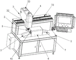
Fig. 1 is a schematic structural diagram of a double-station laser cutting machine according to this embodiment.
Reference numerals:
the cutting machine comprises a rack platform 1 and a cutting support seat 2;
the Y-axis linear module 3, a Y-axis linear guide rail 31, a Y-axis sliding block 32 and a Y-axis motor driving box 33;
a Z-axis linear module 4 and a laser cutting head 5;
a workpiece fixing device 6, a left rotating chuck 61;
a waste collection tank 7.
Detailed Description
The present invention will be further described with reference to the following examples and accompanying drawings.
A specific embodiment of the double-station laser cutting machine of this embodiment is shown in fig. 1, and includes a rack platform 1, a cutting support base 2 installed on the rack platform 1, a Y-axis linear module 3 installed on the cutting support base 2, a Z-axis linear module 4 connected to the Y-axis linear module 3, and a laser cutting head 5 connected to the Z-axis linear module 4, wherein a workpiece fixing device 6 is disposed below the laser cutting head 5; the workpiece fixing device 6 comprises a left air cylinder, a right air cylinder, a left rotating chuck 61 and a right rotating chuck which are fixed on the rack platform 1, an air cylinder rod of the left air cylinder is connected with the left rotating chuck 61, and an air cylinder rod of the right air cylinder is connected with the right rotating chuck. By adopting the structure, when cutting, the two stations of the workpiece fixing device 6, namely the left rotating chuck 61 and the right rotating chuck are inserted into the workpiece, the program is started to start cutting, the Y-axis linear module 3 drives the laser cutting head 5 to move to the right side (or the left side is taken as the starting side) from the middle starting position, the Z-axis linear module 4 descends to cut the right workpiece after the position is reached, the Z-axis linear module 4 ascends to the highest point to prevent collision after the cutting is finished, and then moves to the left station which is the opposite side, and simultaneously the right rotating chuck loosens the workpiece, a worker takes off the cut workpiece and inserts a new workpiece to be cut, after the laser cutting head 5 reaches the left workpiece position in the process, the left rotating chuck 61 clamps the workpiece, the Z-axis linear module 4 descends to cut the left workpiece, the Z-axis linear module 4 ascends to the highest point after the cutting is finished, and then the actions are repeated, and (5) performing left-right circular cutting. Therefore, reciprocating cutting at two processing stations can be realized, cutting at another station can be synchronously carried out when a workpiece at one station is replaced, cutting efficiency is greatly improved, time for feeding and discharging the workpiece is saved, the whole equipment is compact in structural design, more space cannot be additionally increased on the basis of original equipment, and space utilization rate of the equipment is improved.
Specifically, the Y-axis linear module 3 includes a Y-axis linear guide 31 disposed on the cutting support base 2, a Y-axis slider 32 connected to the Y-axis linear guide 31, and a Y-axis motor drive box 33 fixed to the Y-axis slider 32, and a Y-axis servo motor is disposed in the Y-axis motor drive box 33.
Specifically, the Z-axis linear module 4 includes a Z-axis linear guide fixed to the Y-axis motor driving box 33, a Z-axis servo motor, a lead screw connected to the Z-axis servo motor, and a lifting slide plate connected to the lead screw, wherein a Z-axis slider is disposed on the Z-axis linear guide, and the lifting slide plate is connected to the Z-axis slider.
Specifically, the laser cutting head 5 is connected with the lifting sliding plate through a mounting seat.
Specifically, the left rotary chuck 61 and the right rotary chuck are both provided with clamping parts, and clamping grooves for inserting workpieces are formed in the clamping parts.
In this embodiment, the left rotary chuck 61 and the right rotary chuck are all provided with garbage collection groove 7 in the below, and as preferred embodiment, the bottom of garbage collection groove 7 is the inclined plane that the slope set up down to but the waste material of being convenient for to cut the production is collected through this inclined plane automatic sliding.
The working principle of the utility model is as follows:
when the cutting machine works, two stations of a workpiece fixing device 6, namely a left rotating chuck 61 and a right rotating chuck are inserted into a workpiece, a program is started to start cutting, a Y-axis linear module 3 drives a laser cutting head 5 to move towards the right side (or the left side is taken as a starting side) from a middle starting position, a Z-axis linear module 4 descends to cut a right workpiece after the station is in place, the Z-axis linear module 4 ascends to the highest point to prevent collision after the cutting is finished, the Z-axis linear module 4 moves towards the left station, the right rotating chuck loosens the workpiece, a worker takes off the cut workpiece and inserts a new workpiece needing to be cut, after the laser cutting head 5 reaches the left workpiece position in the process, the left rotating chuck 61 clamps the workpiece, the Z-axis linear module 4 descends to cut the left workpiece, the Z-axis linear module 4 ascends to the highest point after the cutting is finished, and the actions are repeated, and circularly cutting the left station and the right station.
Compared with the prior art, the utility model discloses a duplex position laser cutting machine can be at the reciprocal cutting of two processing station, can carry out the cutting of another station in step when changing the work piece of one of them station, thereby improved cutting efficiency greatly, practiced thrift the time of the last unloading of changing the work piece at every turn, whole equipment structural design is compact moreover, can not additionally increase more space on the basis of existing equipment, the space utilization of equipment has been promoted, thereby satisfy the demand of scale production better, very good application prospect has.
It should be finally noted that the above embodiments are only intended to illustrate the technical solutions of the present invention, and not to limit the scope of the present invention, and although the present invention has been described in detail with reference to the preferred embodiments, it should be understood by those skilled in the art that the technical solutions of the present invention can be modified or replaced with equivalents without departing from the spirit and scope of the technical solutions of the present invention.
Claims (6)
1. The utility model provides a duplex position laser cutting machine which characterized in that: the cutting machine comprises a rack platform, a cutting support seat arranged on the rack platform, a Y-axis linear module arranged on the cutting support seat, a Z-axis linear module connected with the Y-axis linear module, and a laser cutting head connected with the Z-axis linear module, wherein a workpiece fixing device is arranged below the laser cutting head;
the workpiece fixing device comprises a left air cylinder, a right air cylinder, a left rotating chuck and a right rotating chuck which are fixed on the rack platform, wherein an air cylinder rod of the left air cylinder is connected with the left rotating chuck, and an air cylinder rod of the right air cylinder is connected with the right rotating chuck;
and waste collecting grooves are formed below the left rotary chuck and the right rotary chuck.
2. The double-station laser cutting machine according to claim 1, characterized in that: the Y-axis linear module comprises a Y-axis linear guide rail arranged on the cutting support seat, a Y-axis sliding block connected with the Y-axis linear guide rail and a Y-axis motor driving box fixed on the Y-axis sliding block, and a Y-axis servo motor is arranged in the Y-axis motor driving box.
3. The double-station laser cutting machine according to claim 2, characterized in that: the Z-axis linear module comprises a Z-axis linear guide rail fixed on the Y-axis motor driving box, a Z-axis servo motor, a screw rod connected with the Z-axis servo motor and a lifting sliding plate connected with the screw rod, wherein a Z-axis sliding block is arranged on the Z-axis linear guide rail, and the lifting sliding plate is connected with the Z-axis sliding block.
4. The double-station laser cutting machine according to claim 3, characterized in that: the laser cutting head is connected with the lifting sliding plate through a mounting seat.
5. The double-station laser cutting machine according to claim 1, characterized in that: the left rotating chuck and the right rotating chuck are both provided with clamping parts, and clamping grooves for inserting workpieces are formed in the clamping parts.
6. The double-station laser cutting machine according to claim 1, characterized in that: the bottom of the waste collecting tank is an inclined plane which is arranged in a downward inclined mode.
Priority Applications (1)
| Application Number | Priority Date | Filing Date | Title |
|---|---|---|---|
| CN202221077905.5U CN217433379U (en) | 2022-05-05 | 2022-05-05 | Double-station laser cutting machine |
Applications Claiming Priority (1)
| Application Number | Priority Date | Filing Date | Title |
|---|---|---|---|
| CN202221077905.5U CN217433379U (en) | 2022-05-05 | 2022-05-05 | Double-station laser cutting machine |
Publications (1)
| Publication Number | Publication Date |
|---|---|
| CN217433379U true CN217433379U (en) | 2022-09-16 |
Family
ID=83219101
Family Applications (1)
| Application Number | Title | Priority Date | Filing Date |
|---|---|---|---|
| CN202221077905.5U Expired - Fee Related CN217433379U (en) | 2022-05-05 | 2022-05-05 | Double-station laser cutting machine |
Country Status (1)
| Country | Link |
|---|---|
| CN (1) | CN217433379U (en) |
Cited By (1)
| Publication number | Priority date | Publication date | Assignee | Title |
|---|---|---|---|---|
| CN117718608A (en) * | 2024-01-25 | 2024-03-19 | 深圳市锐伺科技有限公司 | A laser cutting automation device |
-
2022
- 2022-05-05 CN CN202221077905.5U patent/CN217433379U/en not_active Expired - Fee Related
Cited By (1)
| Publication number | Priority date | Publication date | Assignee | Title |
|---|---|---|---|---|
| CN117718608A (en) * | 2024-01-25 | 2024-03-19 | 深圳市锐伺科技有限公司 | A laser cutting automation device |
Similar Documents
| Publication | Publication Date | Title |
|---|---|---|
| CN204639615U (en) | The one-body molded machining center of tubing based on Internet of Things Intelligent Manufacturing Technology | |
| CN102896561A (en) | Fully automatic numerical control drill cutter grinding machine | |
| CN102935591A (en) | Compound type numerically-controlled machine tool | |
| CN109175730A (en) | The more chuck cutter devices of completely mobile and method | |
| CN216759145U (en) | Numerical control lathe piece collection device | |
| CN201205599Y (en) | Full-automatic numerically control lathe for metal tube material | |
| CN105328500A (en) | Numerical control machine tool internally provided with automatic feeding and discharging mechanism and method for conducting workpiece feeding and discharging | |
| CN212398486U (en) | Automatic laser cutting and forming machine | |
| CN116394018A (en) | A double-channel machining center | |
| CN212793308U (en) | Copper pipe cutting equipment for air conditioner installation | |
| CN211806658U (en) | Door plate chamfering device | |
| CN209850462U (en) | Small-size row sword lathe built-in unloader and contain its lathe | |
| CN219189009U (en) | Laser cutting machine | |
| CN206185488U (en) | Lathe with tool magazine device | |
| CN205996622U (en) | Carving machine with tool magazine device | |
| CN104827302A (en) | Double-head multi-purpose single-sided machine tool | |
| CN202801843U (en) | Horizontal-type tooth engraving machine | |
| CN210254728U (en) | Full-automatic cutting device of outdoor furniture tubular product | |
| CN206732565U (en) | A kind of horizontal mechanical processing work platform | |
| CN207915668U (en) | A kind of high efficiency cutting equipment for back | |
| CN222608036U (en) | Movable beam vertical type numerical control lathe | |
| CN210188501U (en) | Device of full automated processing bolt gasket | |
| CN216939690U (en) | Convenient to use's metal cutting machine | |
| CN202344190U (en) | Machine tool for machining special parts | |
| CN2333478Y (en) | Focusing head controller for diamond saw laser welder |
Legal Events
| Date | Code | Title | Description |
|---|---|---|---|
| GR01 | Patent grant | ||
| GR01 | Patent grant | ||
| CF01 | Termination of patent right due to non-payment of annual fee | ||
| CF01 | Termination of patent right due to non-payment of annual fee |
Granted publication date: 20220916 |