CN217423514U - A long-distance multi-stage transport system for pollutant targeting with adjustable airflow direction - Google Patents
A long-distance multi-stage transport system for pollutant targeting with adjustable airflow direction Download PDFInfo
- Publication number
- CN217423514U CN217423514U CN202220949530.0U CN202220949530U CN217423514U CN 217423514 U CN217423514 U CN 217423514U CN 202220949530 U CN202220949530 U CN 202220949530U CN 217423514 U CN217423514 U CN 217423514U
- Authority
- CN
- China
- Prior art keywords
- air
- air supply
- long
- building
- supply device
- Prior art date
- Legal status (The legal status is an assumption and is not a legal conclusion. Google has not performed a legal analysis and makes no representation as to the accuracy of the status listed.)
- Active
Links
Images





Landscapes
- Ventilation (AREA)
- Refuse Collection And Transfer (AREA)
Abstract
本实用新型公开了一种气流方向可调的污染物靶向长距离多级输运系统,包括设置在建筑物内的远距离送风装置和排风装置,还包括移动接力送风装置;所述远距离送风装置用于向建筑物内输送气流;移动接力送风装置用于将捕集到的污染气流输送给排风装置;排风装置用于将捕集到的污染气流排出建筑物。本实用新型通过对部件结构的合理设置,尤其通过设置单个或多个角度可调的移动接力送风装置,改变了建筑物内气流的输送方向,达到诱导污染气流向排放口扩散的效果。

The utility model discloses a long-distance multi-level transportation system for pollutant targeting with adjustable airflow direction, which comprises a long-distance air supply device and an air exhaust device arranged in a building, and also includes a mobile relay air supply device; The long-distance air supply device is used to deliver airflow into the building; the mobile relay air supply device is used to deliver the captured polluted airflow to the exhaust device; the exhaust device is used to discharge the captured polluted airflow out of the building. . The utility model changes the conveying direction of the airflow in the building by rationally arranging the component structure, especially by arranging single or multiple angle-adjustable mobile relay air supply devices, and achieves the effect of inducing the polluted airflow to diffuse to the discharge port.
Description
技术领域technical field
本实用新型属于大空间气态污染物控制技术领域,具体涉及一种气流方向可调的污染物靶向长距离多级输运系统。The utility model belongs to the technical field of control of gaseous pollutants in large spaces, in particular to a long-distance multi-stage transportation system for targeting pollutants with adjustable airflow direction.
背景技术Background technique
目前,诸如焊接厂房一类的工业厂房越来越趋于高大化,这些厂房中污染源具有数量多、位置不固定等特点。全面通风是通过引入新鲜空气将整个厂房内的有害气体浓度降低,再通过排风口将稀释后的有害气体排出厂房,这种方式存在通风效率差、能耗高等劣势,因此,大多数企业都采用局部通风的方式来控制厂房内的污染物,局部排风罩是就成为了最常用的一种局部通风装置。局部排风罩往往需要安装在距离污染物较近的位置才会有较好的控制效果,但是在很多生产过程中,由于受到厂房空间和工艺操作的限制,很难将排风罩安装在污染源附近,而且采用局部排风罩很难同时实现对多个污染源的控制。因此,亟需研发一种适用于上述大空间厂房的污染物靶向长距离多级输运系统。At present, industrial plants such as welding plants tend to be larger and larger, and the pollution sources in these plants are characterized by a large number and irregular locations. Comprehensive ventilation is to reduce the concentration of harmful gases in the entire workshop by introducing fresh air, and then discharge the diluted harmful gases out of the workshop through the exhaust port. This method has the disadvantages of poor ventilation efficiency and high energy consumption. Therefore, most enterprises have Local ventilation is used to control pollutants in the workshop, and the local exhaust hood has become the most commonly used local ventilation device. Local exhaust hoods often need to be installed close to the pollutants to have a better control effect. However, in many production processes, due to the limitations of plant space and process operations, it is difficult to install the exhaust hood at the pollution source. Nearby, and it is difficult to control multiple pollution sources at the same time by using a local exhaust hood. Therefore, there is an urgent need to develop a pollutant-targeted long-distance multi-stage transport system suitable for the above-mentioned large-space factory buildings.
实用新型内容Utility model content
针对现有技术存在的不足,本实用新型的目的在于,提出一种气流方向可调的污染物靶向长距离多级输运系统,以解决现有技术中局部排风装置由于位置受限而导致无法实现远距离输送污染物的问题。Aiming at the deficiencies of the prior art, the purpose of the present invention is to propose a long-distance multi-level transport system for pollutant targeting with adjustable airflow direction, so as to solve the problem of the local exhaust device in the prior art due to the limited location. This results in the inability to transport pollutants over long distances.
为实现上述目的,本实用新型采取的技术方案包括:In order to achieve the above-mentioned purpose, the technical scheme adopted by the present utility model includes:
一种气流方向可调的污染物靶向长距离多级输运系统,包括设置在建筑物内的远距离送风装置和排风装置,还包括移动接力送风装置;A pollutant-targeting long-distance multi-stage transportation system with adjustable airflow direction, comprising a long-distance air supply device and an air exhaust device arranged in a building, and a mobile relay air supply device;
所述远距离送风装置包括设置有送风腔体的第一外壳体,所述送风腔体内设置有送风机,且所述第一外壳体的两端分别设置与所述送风腔体连通的第一进风口和送风口,所述第一进风口与开设在建筑物第一侧壁下部的主进风口连通;The remote air supply device includes a first outer casing provided with an air supply cavity, a blower is arranged in the air supply cavity, and both ends of the first outer casing are respectively arranged to communicate with the air supply cavity the first air inlet and the air supply outlet, the first air inlet is communicated with the main air inlet opened at the lower part of the first side wall of the building;
所述排风装置设置在建筑物第二侧壁的上部,所述建筑物第二侧壁与所述建筑物第一侧壁相对设置,每个排风装置对应一个或多个移动接力送风装置;所述排风装置包括排风管道,所述排风管道上连接有排风口朝下的排风罩;The air exhaust device is arranged on the upper part of the second side wall of the building, the second side wall of the building is arranged opposite to the first side wall of the building, and each air exhaust device corresponds to one or more mobile relays for air supply The air exhaust device includes an air exhaust duct, and an air exhaust hood with an air outlet facing downward is connected to the air exhaust duct;
所述远距离送风装置用于向建筑物内输送气流;移动接力送风装置用于将捕集到的污染气流输送给排风装置;排风装置用于将捕集到的污染气流排出建筑物。The long-distance air supply device is used for conveying airflow into the building; the mobile relay air supply device is used for conveying the captured polluted airflow to the exhaust device; the exhaust device is used to discharge the captured polluted airflow out of the building thing.
本实用新型还具有以下技术特征:The utility model also has the following technical features:
具体的,所述移动接力送风装置包括底座,所述底座上设置有安装箱,所述安装箱内设置有风机组件,且安装箱上还开设有第二进风口;底座上还竖直设置有与所述安装箱连通的中空升降支架,所述中空升降支架的上部设置有与其连通的环形风筒,所述环形风筒内设有风道,所述环形风筒内侧壁上开设有气体喷射口,所述环形风筒内环面朝向排风口的一端设置有环形防扩散罩。Specifically, the mobile relay air supply device includes a base, a mounting box is arranged on the base, a fan assembly is arranged in the mounting box, and a second air inlet is also opened on the mounting box; the base is also vertically arranged There is a hollow lifting bracket communicated with the installation box, the upper part of the hollow lifting bracket is provided with an annular air duct communicating with it, an air duct is arranged in the annular air duct, and a gas is opened on the inner side wall of the annular air duct The spray port is provided with an annular anti-diffusion cover at one end of the inner annular surface of the annular air duct facing the air outlet.
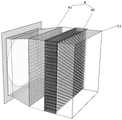
更进一步的,所述第一外壳体内靠近送风口的位置上还设置有整流机构,所述整流机构包括沿气流方向顺序设置的多孔板和蜂窝整流板。Furthermore, a rectifying mechanism is further provided in the first outer casing at a position close to the air supply port, and the rectifying mechanism includes a porous plate and a honeycomb rectifying plate sequentially arranged along the airflow direction.
更进一步的,所述的底座的底面四角上安装有万向轮。Further, universal wheels are installed on the four corners of the bottom surface of the base.
更进一步的,所述排风罩的风口轴线与水平方向的夹角为30°~60°。Further, the included angle between the axis of the air outlet of the exhaust hood and the horizontal direction is 30°˜60°.
更进一步的,所述环形防扩散罩(35)的风口轴线与竖直方向的夹角为0°~60°。Further, the included angle between the axis of the tuyere of the annular anti-diffusion cover (35) and the vertical direction is 0°˜60°.
更进一步的,所述安装箱上还设置有烟雾传感器。Further, the installation box is also provided with a smoke sensor.
与现有技术相比,本实用新型的优点为:Compared with the prior art, the advantages of the present utility model are:
(1)本实用新型通过对部件结构的合理设置,尤其通过设置单个或多个角度可调的移动接力送风装置,改变了建筑物内气流的输送方向,达到诱导污染气流向排放口扩散的效果,同时减小了排风装置的气流吸入速度随距离的衰减率,有效屏蔽了建筑物内侧向气流等环境风,避免了污染物逃逸、达到了高效捕集污染物的效果。(1) The present utility model changes the conveying direction of the airflow in the building by rationally setting the component structure, especially by setting a single or multiple adjustable angle-adjustable mobile relay air supply devices, so as to induce the pollutant airflow to diffuse to the discharge port. At the same time, it reduces the attenuation rate of the airflow suction speed of the exhaust device with distance, effectively shields the ambient wind such as the inward airflow inside the building, avoids the escape of pollutants, and achieves the effect of efficiently capturing pollutants.
(2)本实用新型通过设置整流机构,尤其是蜂窝孔板的整流作用减少了送风气流的扩散,可以解决污染物输运过程中动力消散导致的输送距离近的问题。(2) The utility model reduces the diffusion of the air supply air flow by setting the rectification mechanism, especially the rectification effect of the honeycomb orifice plate, and can solve the problem of short conveying distance caused by power dissipation during the transportation of pollutants.
(3)本实用新型还设置了用于实时监测污染物浓度的烟雾传感器,操作人员可以实现根据实际负荷调节风机组件的转速,从而移动接力送风装置的风速,最终实现节能。(3) The utility model is also provided with a smoke sensor for monitoring the concentration of pollutants in real time. The operator can adjust the rotational speed of the fan assembly according to the actual load, thereby moving the wind speed of the relay air supply device, and finally realizing energy saving.
附图说明Description of drawings
附图是用来提供对本实用新型的进一步理解,并且构成说明书的一部分,与下面的具体实施方式一起用于解释本实用新型,但并不构成对本实用新型的限制。在附图中:The accompanying drawings are used to provide a further understanding of the present utility model, and constitute a part of the specification, and together with the following specific embodiments, are used to explain the present utility model, but do not constitute a limitation to the present utility model. In the attached image:
图1为本发明的系统的整体结构示意图;Fig. 1 is the overall structure schematic diagram of the system of the present invention;
图2为移动接力送风装置结构示意图,其中箭头方向为污染气流的输送方向;2 is a schematic structural diagram of a mobile relay air supply device, wherein the direction of the arrow is the conveying direction of the polluted airflow;
图3为移动接力送风装置局部结构示意图,其中箭头方向为移动接力送风装置内的气流方向;3 is a schematic diagram of the partial structure of the mobile relay air supply device, wherein the direction of the arrow is the airflow direction in the mobile relay air supply device;
图4为移动接力送风装置的设置角度示意图;4 is a schematic diagram of the setting angle of the mobile relay air supply device;
图5为整流机构的结构示意图;5 is a schematic structural diagram of a rectifier mechanism;
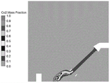
图6为应用例1的污染气流的分布云图;Fig. 6 is the distribution cloud map of the polluted airflow of application example 1;
图7为应用例1的污染气流速度场分布云图;Fig. 7 is the cloud map of the pollution airflow velocity field distribution of application example 1;
图8为应用例1的污染气流输送迹线图。FIG. 8 is a trace diagram of the contaminated air flow in Application Example 1. FIG.
图中各标号表示为:The symbols in the figure are represented as:
1-远距离送风装置,2-排风装置,3-移动接力送风装置,4-整流机构,5-烟雾传感器,11-第一外壳体,21-排风管道,22-排风罩;31- 底座,32-安装箱,33-中空升降支架,34-环形风筒,35-环形防扩散罩;41-多孔板,42-蜂窝整流板,111-第一进风口,112-送风口;311- 万向轮,321-第二进风口,341-气体喷射口。1-remote air supply device, 2-exhaust device, 3-mobile relay air supply device, 4-rectification mechanism, 5-smoke sensor, 11-first outer casing, 21-exhaust duct, 22-exhaust hood ;31- base, 32-installation box, 33-hollow lifting bracket, 34-annular air duct, 35-annular anti-diffusion cover; 41-perforated plate, 42-honeycomb fairing plate, 111-first air inlet, 112-supply Air outlet; 311- universal wheel, 321- second air inlet, 341- gas jet.
具体实施方式Detailed ways
以下给出本实用新型的具体实施例,需要说明的是,本实用新型并不局限于以下具体实施例,凡在本申请技术方案基础上做的等同变换均落入本实用新型的保护范围。Specific embodiments of the present utility model are given below. It should be noted that the present utility model is not limited to the following specific embodiments, and all equivalent transformations made on the basis of the technical solutions of the present application all fall into the protection scope of the present utility model.
需要说明的是,本实用新型中的所有部件,如无特殊说明,全部采用可以从市场上购得的部件。It should be noted that, all components in the present invention, unless otherwise specified, are all components that can be purchased from the market.
本实用新型所用的术语“上”、“下”、“前”、“后”、“顶”、“底”等指示的方位或位置关系仅是为了便于描述本实用新型和简化描述,而不是指示或暗示所指的装置或元件必须具有特定的方位、以特定的方位构造和操作,“内”、“外”是指相应部件轮廓的内和外,不能将上述术语理解为对本实用新型的限制。此外,术语“第一”、“第二”等序数词仅用于描述目的,而不能理解为指示或暗示相对重要性或者隐含指明所指示的技术特征的数量。由此,限定有“第一”、“第二”的特征可以明示或者隐含地包括一个或者更多个该特征。The terms "upper", "lower", "front", "rear", "top", "bottom", etc. used in the present invention indicate the orientation or positional relationship only for the convenience of describing the present invention and simplifying the description, rather than Indicates or implies that the referred device or element must have a specific orientation, be constructed and operated in a specific orientation, and "inner" and "outer" refer to the inside and outside of the contour of the corresponding component, and the above terms should not be construed as a reference to the present invention. limit. In addition, the terms "first", "second" and other ordinal numbers are only used for descriptive purposes, and should not be construed as indicating or implying relative importance or implicitly indicating the quantity of the indicated technical features. Thus, a feature defined as "first" or "second" may expressly or implicitly include one or more of that feature.
在本实用新型中,在未作相反说明的情况下,术语“安装”、“相连”、“连接”、“固定”等术语应做广义理解,例如,可以是固定连接,也可以是可拆卸连接或成一体;可以是机械连接,也可以是电连接;可以是直接相连,也可以通过中间媒介间接相连,可以是两个元件内部的连通或两个元件的相互作用关系。对于本领域的技术人员而言,可以根据具体情况理解上述术语在本实用新型中的具体含义。In the present utility model, unless otherwise stated, terms such as "installation", "connection", "connection" and "fixation" should be understood in a broad sense, for example, it may be a fixed connection or a detachable connection It can be connected or integrated; it can be a mechanical connection or an electrical connection; it can be a direct connection or an indirect connection through an intermediate medium, and it can be the internal communication between the two elements or the interaction relationship between the two elements. For those skilled in the art, the specific meanings of the above terms in the present invention can be understood according to specific situations.
实施例1Example 1
遵从上述技术方案,如图1至图5所示,本实施例公开了一种气流方向可调的污染物靶向长距离多级输运系统,包括设置在建筑物内的远距离送风装置1和排风装置2,还包括移动接力送风装置3;在本实施例中,建筑物包括车间、厂房等。Following the above technical solutions, as shown in FIG. 1 to FIG. 5 , the present embodiment discloses a long-distance multi-stage transportation system for pollutant targeting with adjustable airflow direction, including a long-distance air supply device arranged in a
远距离送风装置1包括设置有送风腔体的第一外壳体11,且第一外壳体11的两端分别设置与送风腔体连通的第一进风口111和送风口112,第一进风口111与开设在建筑物第一侧壁下部的主进风口连通;所述送风腔体内设置有送风机,在送风机的作用下经第一进风口111进入送风腔体内的气流,流经送风腔体后从送风口112进入建筑物内部。The remote
排风装置2设置在建筑物第二侧壁的上部,建筑物第二侧壁与建筑物第一侧壁相对设置;每个排风装置2对应一个或多个移动接力送风装置3;所述排风装置2包括排风管道21,所述排风管道21上连接有排风口朝下的排风罩22;The
每个移动接力送风装置3的送风方向朝向与其对应的排风罩22。The air blowing direction of each mobile relay air blowing device 3 is directed toward its corresponding
远距离送风装置1用于向建筑物内输送气流;移动接力送风装置 3用于将捕集到的污染气流输送给排风装置2;排风装置2用于将捕集到的污染气流排出建筑物。The remote
在本实施例中,远距离送风装置1和排风装置2分别设置在建筑物相对的第一侧壁和建筑物第二侧壁上,移动接力送风装置3设置在远距离送风装置1和排风装置2中间,污染源位于远距离送风装置1 和移动接力送风装置3之间,远距离送风装置1输送的均匀气流经过污染源后,由于携带了污染源发出的污染物,如烟尘等,变成了污染气流,然后污染气流被移动接力送风装置3抽吸输送,即,本实施例中的远距离送风装置1、污染源、移动接力送风装置3和排风装置2 沿气流输送方向顺次设置。In this embodiment, the remote
作为本实施例的一种优选方案,移动接力送风装置3的结构及工作方式类似于无叶风扇,包括底座31,底座31上设置有安装箱32,安装箱32内设置有风机组件,且安装箱32上还开设有第二进风口 321;底座31上还竖直设置有与安装箱32连通的中空升降支架33,中空升降支架33的上部设置有与其连通的环形风筒34,环形风筒34 内设有风道,环形风筒34内侧壁上开设有气体喷射口341,环形风筒34内环面朝向排风口的一端设置有环形防扩散罩35。As a preferred solution of this embodiment, the structure and working method of the mobile relay air supply device 3 are similar to those of a bladeless fan, including a
建筑物中的环境空气在风机组件的作用下,经第二进风口321进入安装箱32,然后进入与安装箱32连通的中空升降支架33,进入环形风筒34后经气体喷射口341喷出,喷出气流的方向与移动接力装置3的风口轴线平行,高速喷出的气流使得在环形风筒34内产生负压,将环形风筒34附近的污染气流吸入环形风筒34,然后经环形防扩散罩35送出,实现污染气流的接力传输。Under the action of the fan assembly, the ambient air in the building enters the
作为优选,安装箱内还设置有用于控制风机组件运转的常规控制单元,控制单元用于控制风机组件的开启、关闭和转速。Preferably, the installation box is further provided with a conventional control unit for controlling the operation of the fan assembly, and the control unit is used for controlling the opening, closing and rotation speed of the fan assembly.
作为本实施例的一种优选方案,送风腔体内靠近送风口112的位置上还设置有整流机构4,整流机构4包括沿气流方向顺序设置的多孔板41和蜂窝整流板42。被吸入的环境空气进入送气腔体后经接力整流机构4整流后排放到建筑物中。整流机构4上方的第一外壳体 11上开设有更换窗口,更换窗口上设置有可拆卸的盖板,盖板可以通过卡扣固定在更换窗口上,且盖板的上表面上设置把手,以便于更换整流机构。As a preferred solution of this embodiment, a
作为本实施例的一种优选方案,的底座31的底面四角上安装有万向轮311。操作人员可以更加灵活地根据污染源散发点、远距离送风装置1和排风装置2的相对位置,布设移动接力送风装置3,而且接力送风装置3的数量可以为多个,根据需要,在一个污染源处设置多个朝向同一排风罩22的多个接力送风装置3。As a preferred solution of this embodiment,
作为本实施例的一种优选方案,排风罩的风口轴线与水平方向的夹角为30°~60°As a preferred solution of this embodiment, the included angle between the axis of the air outlet of the exhaust hood and the horizontal direction is 30° to 60°
作为本实施例的一种优选方案,环形防扩散罩35的风口轴线与竖直方向的夹角为0°~60°,由于底座下方设置万向轮,所以移动接力送风装置3可以任意移动位置和调整角度,优选的,其在水平方向上移动时,第二进风口321的进风轴线的变化角度为±45°。As a preferred solution of this embodiment, the angle between the axis of the tuyere of the
作为本实施例的一种优选方案,安装箱32上还设置有烟雾传感器5。As a preferred solution of this embodiment, the
本实施例的使用过程如下:The use process of this embodiment is as follows:
在诸如车间、厂房一类的建筑物的相对侧壁上,分别开设一个或多个主进风口/主出风口,然后完成远距离送风装置1和排风装置2的安装,综合考虑污染源的位置、远距离送风装置1和排风装置2的相对位置,选择一个或多个移动接力送风装置3,在污染源散发出污染物时,启动多级远距离输运污染物系统,使污染物随气流输送到与排风装置2相连的净化装置中,并经过净化后排放。On the opposite side walls of buildings such as workshops and workshops, one or more main air inlets/main air outlets are opened respectively, and then the installation of the remote
应用例1Application example 1
为了验证本实用新型的可行性和有效性,根据本实用新型进行计算流体学模拟,分别图6~图8。In order to verify the feasibility and effectiveness of the present utility model, computational fluids simulations are carried out according to the present utility model, as shown in Figs. 6 to 8 respectively.
由图6可以看出,污染源散发出包括灰尘、烟雾在内的污染物,在送风气流的作用下扩散,但是扩散高度很低并易发生转向,污染物通过移动接力送风装置3后运动方向转向排风罩22方向,并随移动接力送风装置3的气流运动到排风罩22附近,由排风罩22吸入,污染物的控制效果较好,排风罩22的捕集效率接近100%。As can be seen from Figure 6, the pollution source emits pollutants including dust and smoke, which diffuse under the action of the air supply, but the diffusion height is very low and it is easy to turn around. The pollutants move after moving the relay air supply device 3. The direction turns to the direction of the
由图7可以看出,远距离送风装置1送出的气流速度较小,送风射流扩散程度极小,污染气流上升一段距离后被送风射流压制,并且随送风气流改变方向,向移动接力送风装置3附近偏转,移动接力送风装置3产生的气流速度较高,出口气流分布均匀,沿程扩散很小,射流运动较远距离后仍保持较大的动能,输送距离较远,因此可以保证污染气流的远距离输送。It can be seen from Figure 7 that the air velocity sent by the long-distance
由图8可以看出,由污染源散发的污染物在本实用新型的系统的控制下沿着预定轨迹定向进入排风罩22,实现了污染物的远距离接力定向控制,大大提高了污染物的控制效果It can be seen from FIG. 8 that the pollutants emitted by the pollution source are directed into the
以上结合附图详细描述了本公开的优选实施方式,但是,本公开并不限于上述实施方式中的具体细节,在本公开的技术构思范围内,可以对本公开的技术方案进行多种简单变型,这些简单变型均属于本公开的保护范围。The preferred embodiments of the present disclosure have been described above in detail with reference to the accompanying drawings. However, the present disclosure is not limited to the specific details of the above-mentioned embodiments. Various simple modifications can be made to the technical solutions of the present disclosure within the scope of the technical concept of the present disclosure. These simple modifications all fall within the protection scope of the present disclosure.
另外需要说明的是,在上述具体实施方式中所描述的各个具体技术特征,在不矛盾的情况下,可以通过任何合适的方式进行组合,为了避免不必要的重复,本公开对各种可能的组合方式不再另行说明。此外,本发公开的各种不同的实施方式之间也可以进行任意组合,只要其不违背本公开的思想,其同样应当视为本公开所实用新型的内容。In addition, it should be noted that the various specific technical features described in the above-mentioned specific embodiments can be combined in any suitable manner unless they are inconsistent. In order to avoid unnecessary repetition, the present disclosure provides The combination method will not be specified otherwise. In addition, the various embodiments disclosed in the present disclosure can also be combined arbitrarily, as long as they do not violate the spirit of the present disclosure, they should also be regarded as the content of the utility model disclosed in the present disclosure.
Claims (7)
Priority Applications (1)
| Application Number | Priority Date | Filing Date | Title |
|---|---|---|---|
| CN202220949530.0U CN217423514U (en) | 2022-04-22 | 2022-04-22 | A long-distance multi-stage transport system for pollutant targeting with adjustable airflow direction |
Applications Claiming Priority (1)
| Application Number | Priority Date | Filing Date | Title |
|---|---|---|---|
| CN202220949530.0U CN217423514U (en) | 2022-04-22 | 2022-04-22 | A long-distance multi-stage transport system for pollutant targeting with adjustable airflow direction |
Publications (1)
| Publication Number | Publication Date |
|---|---|
| CN217423514U true CN217423514U (en) | 2022-09-13 |
Family
ID=83183284
Family Applications (1)
| Application Number | Title | Priority Date | Filing Date |
|---|---|---|---|
| CN202220949530.0U Active CN217423514U (en) | 2022-04-22 | 2022-04-22 | A long-distance multi-stage transport system for pollutant targeting with adjustable airflow direction |
Country Status (1)
| Country | Link |
|---|---|
| CN (1) | CN217423514U (en) |
Cited By (2)
| Publication number | Priority date | Publication date | Assignee | Title |
|---|---|---|---|---|
| CN114877454A (en) * | 2022-04-22 | 2022-08-09 | 西安建筑科技大学 | Long-distance multi-stage transport system and method for pollutant targeting with adjustable airflow direction |
| JP7699686B1 (en) | 2024-03-19 | 2025-06-27 | 株式会社大気社 | Exhaust system |
-
2022
- 2022-04-22 CN CN202220949530.0U patent/CN217423514U/en active Active
Cited By (3)
| Publication number | Priority date | Publication date | Assignee | Title |
|---|---|---|---|---|
| CN114877454A (en) * | 2022-04-22 | 2022-08-09 | 西安建筑科技大学 | Long-distance multi-stage transport system and method for pollutant targeting with adjustable airflow direction |
| JP7699686B1 (en) | 2024-03-19 | 2025-06-27 | 株式会社大気社 | Exhaust system |
| JP2025144114A (en) * | 2024-03-19 | 2025-10-02 | 株式会社大気社 | exhaust system |
Similar Documents
| Publication | Publication Date | Title |
|---|---|---|
| CN101619881B (en) | Dedusting system of whole factory building | |
| CN209084996U (en) | A kind of blowing and drawing type weldering dust collection system being adjustable room temperature and humidity | |
| CN112090912A (en) | Modularized air curtain separation downdraft welding smoke dust collecting device | |
| CN203454331U (en) | Airflow jet carrier type ventilating system for large factory building | |
| CN213967314U (en) | A marine spraying and waste gas treatment device | |
| CN209680765U (en) | A blowing suction type welding fume dust removal system with a blower | |
| CN102937318A (en) | Ventilating device | |
| CN204246987U (en) | A kind of safety cabinet gas discharging Rose Box | |
| CN217357368U (en) | Multi-stage remote pollutant transport system | |
| CN114877454A (en) | Long-distance multi-stage transport system and method for pollutant targeting with adjustable airflow direction | |
| CN207254900U (en) | Blowing and drawing type dust pelletizing system | |
| CN207102235U (en) | A kind of low concentration VOC purifying processing devices | |
| CN103993125B (en) | Air-curtain type converter secondary flue gas capturing device | |
| CN209905773U (en) | Dust device along line of belt conveyor | |
| CN216953399U (en) | Welding fume collecting and purifying system for tall and big factory building | |
| CN109772079B (en) | Efficient replacement type recirculating ventilation cluster system | |
| CN118668028B (en) | Copper converter dust collection device induced by large space single-side high-speed jet | |
| CN114754447A (en) | Multi-stage long-distance pollutant transporting system and method | |
| CN205628855U (en) | Welding multi -angle dust collector | |
| CN206677787U (en) | Dust-free workshop sandblasting purification device | |
| CN201500611U (en) | painting room | |
| CN113294870A (en) | Welding fume collecting and purifying system for tall and big factory building | |
| CN207253935U (en) | A kind of movable type industrial fumes processing unit | |
| CN214307446U (en) | Welding shop new trend replacement system | |
| CN221674729U (en) | An exhaust system for a paint spraying room |
Legal Events
| Date | Code | Title | Description |
|---|---|---|---|
| GR01 | Patent grant | ||
| GR01 | Patent grant |