CN217422790U - a level bracket - Google Patents
a level bracket Download PDFInfo
- Publication number
- CN217422790U CN217422790U CN202220904756.9U CN202220904756U CN217422790U CN 217422790 U CN217422790 U CN 217422790U CN 202220904756 U CN202220904756 U CN 202220904756U CN 217422790 U CN217422790 U CN 217422790U
- Authority
- CN
- China
- Prior art keywords
- sleeve
- spherical
- bracket
- fixed
- shaped bracket
- Prior art date
- Legal status (The legal status is an assumption and is not a legal conclusion. Google has not performed a legal analysis and makes no representation as to the accuracy of the status listed.)
- Active
Links
Images


Landscapes
- Pivots And Pivotal Connections (AREA)
Abstract
一种水平仪支架,包括底座,所述底座上设置有升降支架,所述升降支架的顶部固定有球形套,所述球形套中安装有球体,所述球体的正下方固定有连杆,所述连杆的下端悬挂有水平仪;所述球形套的上方设置有压杆,且压杆的中部具有与球体吻合的球形凹槽;所述压杆的一端铰接在升降支架的顶部、另一端通过拉簧与升降支架的顶部连接,进而使所述球形凹槽扣合在球体上将球形套中万向转动的球体固定。本实用新型以克服现有技术的不足,实现了水平仪的全自动调节,提高了工作效率,且结构简单、操作方便。

A level support includes a base, a lifting support is arranged on the base, a spherical sleeve is fixed on the top of the lifting support, a sphere is installed in the spherical sleeve, and a connecting rod is fixed directly under the spherical body, and the A level is suspended from the lower end of the connecting rod; a pressing rod is arranged above the spherical sleeve, and the middle of the pressing rod has a spherical groove that matches the sphere; one end of the pressing rod is hinged on the top of the lifting bracket, and the other end is pulled The spring is connected with the top of the lifting bracket, so that the spherical groove is fastened on the spherical body to fix the universally rotating spherical body in the spherical sleeve. The utility model overcomes the deficiencies of the prior art, realizes the automatic adjustment of the spirit level, improves the work efficiency, and has simple structure and convenient operation.
Description
技术领域technical field
本实用新型涉及测量仪器技术领域,具体涉及一种水平仪支架。The utility model relates to the technical field of measuring instruments, in particular to a level bracket.
背景技术Background technique
水平仪广泛应用于建筑、装饰、装潢及机械安装等领域,用来制定水平基准。特别是随着激光技术在测量工具上的应用,激光水平仪已经越来越被广大用户所接受,现有技术中激光水平仪与三脚架配合使用,通过调节三角架的三个脚来进行水平调节,因此,每次更换测量地点或调整测量高度时都要进行三个脚的调节,调节速度慢、工作量大且工作效率低下。Spirit levels are widely used in the fields of construction, decoration, decoration and mechanical installation to establish level benchmarks. Especially with the application of laser technology in measuring tools, the laser level has been more and more accepted by the majority of users. In the prior art, the laser level is used in conjunction with a tripod, and the level is adjusted by adjusting the three legs of the tripod. Therefore, , every time the measurement location is changed or the measurement height is adjusted, the adjustment of the three feet must be carried out, the adjustment speed is slow, the workload is large and the work efficiency is low.
实用新型内容Utility model content
本实用新型提供一种水平仪支架,以克服现有技术的不足。The utility model provides a level bracket to overcome the deficiencies of the prior art.
本实用新型所采用的技术方案是:一种水平仪支架,包括底座,所述底座上设置有升降支架,所述升降支架的顶部固定有球形套,所述球形套中安装有球体,所述球体的正下方固定有连杆,所述连杆的下端悬挂有水平仪;所述球形套的上方设置有压杆,且压杆的中部具有与球体吻合的球形凹槽;所述压杆的一端铰接在升降支架的顶部、另一端通过拉簧与升降支架的顶部连接,进而使所述球形凹槽扣合在球体上将球形套中万向转动的球体固定。The technical scheme adopted by the utility model is as follows: a level support includes a base, a lifting support is arranged on the base, a spherical sleeve is fixed on the top of the lifting support, a spherical body is installed in the spherical sleeve, and the spherical body A connecting rod is fixed directly below the connecting rod, and a spirit level is suspended at the lower end of the connecting rod; a pressure rod is arranged above the spherical sleeve, and the middle part of the pressure rod has a spherical groove that matches the sphere; one end of the pressure rod is hinged The top and the other end of the lifting bracket are connected to the top of the lifting bracket through a tension spring, so that the spherical groove is fastened on the spherical body to fix the universally rotating ball in the spherical sleeve.
所述球形凹槽上粘接有防滑胶皮。The spherical groove is bonded with a non-slip rubber.
所述升降支架包括套筒、L型支架及电动伸缩杆,所述套筒垂直固定在底座上,所述L型支架的竖直臂插装在套筒中,所述球形套固定在L型支架的水平臂上,所述压杆的一端铰接在L型支架的水平臂的顶部、另一端通过拉簧与L型支架的水平臂的顶部连接;所述电动伸缩杆的固定端与套筒的外壁固定,所述电动伸缩杆的活动端与L型支架的水平臂铰接,推动L型支架沿套筒上下移动。The lifting bracket includes a sleeve, an L-shaped bracket and an electric telescopic rod. The sleeve is vertically fixed on the base, the vertical arm of the L-shaped bracket is inserted into the sleeve, and the spherical sleeve is fixed on the L-shaped bracket. On the horizontal arm of the bracket, one end of the pressing rod is hinged on the top of the horizontal arm of the L-shaped bracket, and the other end is connected with the top of the horizontal arm of the L-shaped bracket through a tension spring; the fixed end of the electric telescopic rod is connected to the sleeve The outer wall of the telescopic rod is fixed, the movable end of the electric telescopic rod is hinged with the horizontal arm of the L-shaped bracket, and the L-shaped bracket is pushed to move up and down along the sleeve.
所述套筒上沿竖直方向设有限位槽,所述L型支架的竖直臂上固定有限位块,所述限位块位于限位槽中且沿限位槽上下移动。The sleeve is provided with a limit slot along the vertical direction, a limit block is fixed on the vertical arm of the L-shaped bracket, and the limit block is located in the limit slot and moves up and down along the limit slot.
所述球形套由第一半圆球形套、第二半圆球形套组合构成,所述第一半圆球形套的两端设有螺纹孔,所述第二半圆球形套的两端设有沉孔,螺钉自沉孔穿入与螺纹孔连接,将第一半圆球形套、第二半圆球形套固定在一起。The spherical sleeve is composed of a combination of a first hemispherical sleeve and a second hemispherical sleeve. The two ends of the first hemispherical sleeve are provided with threaded holes, and the two ends of the second hemispherical sleeve are provided with countersunk holes. The self-sunk hole is penetrated and connected with the threaded hole, and the first hemispherical sleeve and the second hemispherical sleeve are fixed together.
所述压杆的铰接端向上延伸有手柄;所述底座底部装有自带刹车的万向轮。A handle extends upward from the hinged end of the pressing rod; the bottom of the base is provided with a universal wheel with its own brake.
相较于现有技术,本实用新型具有的有益效果:Compared with the prior art, the utility model has the beneficial effects:
本实用新型通过球体与球形套配合,将水平仪悬挂在球体下方,利用球体在球形套内万向转动的原理,可使水平仪通过自重自动调整至水平状态,调节方便、快捷,同时采用电动伸缩杆调节高度,实现了水平仪的全自动调节,提高了工作效率,且结构简单、操作方便。The utility model suspends the spirit level under the sphere through the cooperation of the sphere and the spherical sleeve, and utilizes the principle of universal rotation of the sphere in the spherical sleeve, so that the spirit level can be automatically adjusted to a horizontal state by its own weight, and the adjustment is convenient and fast, and an electric telescopic rod is used at the same time Adjusting the height realizes the automatic adjustment of the spirit level, improves the work efficiency, and has a simple structure and convenient operation.
附图说明Description of drawings
图1是本实用新型结构示意图;Fig. 1 is the structural representation of the present utility model;
图2是本实用新型俯视示意图;Fig. 2 is the top view schematic diagram of the present utility model;
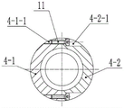
图3是本实用新型球形套剖视示意图。Figure 3 is a schematic cross-sectional view of the spherical sleeve of the present invention.
具体实施方式Detailed ways
下面结合附图1-3和具体实施方式对本实用新型进行详细说明。The present utility model will be described in detail below with reference to the accompanying drawings 1-3 and specific embodiments.
一种水平仪支架,包括底座1,所述底座1上设置有升降支架3,所述升降支架3的顶部固定有球形套4,所述球形套4中安装有球体5,所述球体5的正下方固定有连杆6,所述连杆6的下端悬挂有水平仪2;所述球形套4的上方设置有压杆7,且压杆7的中部具有与球体5吻合的球形凹槽;所述压杆7的一端铰接在升降支架3的顶部、另一端通过拉簧9与升降支架3的顶部连接,进而使所述球形凹槽扣合在球体5上将球形套4中万向转动的球体5固定。A spirit level support includes a
所述球形凹槽上粘接有防滑胶皮8。A
所述升降支架3包括套筒3-1、L型支架3-2及电动伸缩杆3-3,所述套筒3-1垂直固定在底座1上,所述L型支架3-2的竖直臂插装在套筒3-1中,所述球形套4固定在L型支架3-2的水平臂上,所述压杆7的一端铰接在L型支架3-2的水平臂的顶部、另一端通过拉簧9与L型支架3-2的水平臂的顶部连接;所述电动伸缩杆3-3的固定端与套筒3-1的外壁固定,所述电动伸缩杆3-3的活动端与L型支架3-2的水平臂铰接,推动L型支架3-2沿套筒3-1上下移动。The
所述套筒3-1上沿竖直方向设有限位槽3-1-1,所述L型支架3-2的竖直臂上固定有限位块10,所述限位块10位于限位槽3-1-1中且沿限位槽3-1-1上下移动。The sleeve 3-1 is provided with a limit groove 3-1-1 along the vertical direction, a
所述球形套4由第一半圆球形套4-1、第二半圆球形套4-2组合构成,所述第一半圆球形套4-1的两端设有螺纹孔4-1-1,所述第二半圆球形套4-2的两端设有沉孔4-2-1,螺钉11自沉孔4-2-1穿入与螺纹孔4-1-1连接,将第一半圆球形套4-1、第二半圆球形套4-2固定在一起。The spherical sleeve 4 is composed of a combination of a first hemispherical sleeve 4-1 and a second hemispherical sleeve 4-2. Both ends of the first hemispherical sleeve 4-1 are provided with threaded holes 4-1-1, so The two ends of the second hemispherical sleeve 4-2 are provided with countersunk holes 4-2-1, and the
所述压杆7的铰接端向上延伸有手柄12;所述底座1底部装有自带刹车的万向轮13。A
使用时,将水平仪支架放置在待测地点,将磁性配重14吸附在底座上,将水平仪固定在连杆6下方,通过电动伸缩杆3-3调节水平仪支架所需高度,搬动手柄12使压杆7绕铰接轴顺时针旋转,使压杆7另一端向上翘起,压杆7下端的防滑胶皮8与球体5分离,这时球体5下端固定的水平仪2在重力的作用自动调整水平状态,观察水平仪2至水平状态,使手柄12回复初始状态,防滑胶皮8与球体5秘贴,即可进行测量。When in use, place the level bracket on the site to be tested, attach the
球体5优选空心球体,以降低重量,便于移动和携带。The
本实用新型结构简单、操作方便,将水平仪固定在球体下方,通过球体在球形套内任意方向可调整,同时利用水平仪自重使水平仪自动调整水平状态,降低了调节难度,提高了调节效率,采用电动伸缩杆调节升降支架位置高度,实现了水平仪支架高度的自动调节。The utility model has the advantages of simple structure and convenient operation. The level is fixed under the sphere, and can be adjusted in any direction in the spherical sleeve through the sphere. At the same time, the self-weight of the level is used to automatically adjust the level state, which reduces the adjustment difficulty and improves the adjustment efficiency. The telescopic rod adjusts the position and height of the lifting bracket, and realizes the automatic adjustment of the height of the level bracket.
上述实施例,只是本实用新型的较佳实施例,并非用来限制本实用新型的实施范围,故凡以本实用新型权利要求所述内容所做的等同变化,均应包括在本实用新型权利要求范围之内。The above-mentioned embodiments are only preferred embodiments of the present utility model, and are not intended to limit the scope of implementation of the present utility model. Therefore, all equivalent changes made with the contents described in the claims of the present utility model shall be included in the present utility model rights. within the requirements.
Claims (6)
Priority Applications (1)
| Application Number | Priority Date | Filing Date | Title |
|---|---|---|---|
| CN202220904756.9U CN217422790U (en) | 2022-04-19 | 2022-04-19 | a level bracket |
Applications Claiming Priority (1)
| Application Number | Priority Date | Filing Date | Title |
|---|---|---|---|
| CN202220904756.9U CN217422790U (en) | 2022-04-19 | 2022-04-19 | a level bracket |
Publications (1)
| Publication Number | Publication Date |
|---|---|
| CN217422790U true CN217422790U (en) | 2022-09-13 |
Family
ID=83182739
Family Applications (1)
| Application Number | Title | Priority Date | Filing Date |
|---|---|---|---|
| CN202220904756.9U Active CN217422790U (en) | 2022-04-19 | 2022-04-19 | a level bracket |
Country Status (1)
| Country | Link |
|---|---|
| CN (1) | CN217422790U (en) |
Cited By (3)
| Publication number | Priority date | Publication date | Assignee | Title |
|---|---|---|---|---|
| CN115949860A (en) * | 2023-03-03 | 2023-04-11 | 菏泽市自然资源和规划局 | Surveyor's level is used in national soil space planning survey and drawing |
| CN116105038A (en) * | 2023-04-12 | 2023-05-12 | 金田产业发展(山东)集团有限公司 | A surveying and mapping device for land engineering |
| CN118517615A (en) * | 2024-06-26 | 2024-08-20 | 上海大学 | A DR adjustment device |
-
2022
- 2022-04-19 CN CN202220904756.9U patent/CN217422790U/en active Active
Cited By (5)
| Publication number | Priority date | Publication date | Assignee | Title |
|---|---|---|---|---|
| CN115949860A (en) * | 2023-03-03 | 2023-04-11 | 菏泽市自然资源和规划局 | Surveyor's level is used in national soil space planning survey and drawing |
| CN116105038A (en) * | 2023-04-12 | 2023-05-12 | 金田产业发展(山东)集团有限公司 | A surveying and mapping device for land engineering |
| CN116105038B (en) * | 2023-04-12 | 2023-11-21 | 金田产业发展(山东)集团有限公司 | Surveying and mapping device for land engineering |
| CN118517615A (en) * | 2024-06-26 | 2024-08-20 | 上海大学 | A DR adjustment device |
| CN118517615B (en) * | 2024-06-26 | 2026-03-31 | 上海大学 | A DR adjustment device |
Similar Documents
| Publication | Publication Date | Title |
|---|---|---|
| CN206831069U (en) | A kind of instrument of surveying and mapping tripod with warning device | |
| CN214407447U (en) | Fitment is with automatic ann's flat surveyor's level | |
| CN211401228U (en) | Leveling device for all-terrain land surveying and mapping instrument | |
| CN219389238U (en) | Mounting frame of measuring instrument | |
| CN216593374U (en) | Horizontal leveling device | |
| CN114909576B (en) | A supporting device for engineering surveying equipment in building construction | |
| CN205745651U (en) | Adjustable pipeline bracing frame | |
| CN216813525U (en) | Levelling device is used in installation of thermodynamic machine subassembly | |
| CN211502069U (en) | Combined engineering measuring instrument | |
| CN105066849A (en) | Measuring device for friction angle of rock structural planes | |
| CN219510521U (en) | Surveying instrument support | |
| CN220416714U (en) | A surveying and mapping device that is easy to install stably | |
| CN218905321U (en) | Horizontal piece installation auxiliary assembly for interior decoration engineering | |
| CN117405091B (en) | Building construction straightness deviation observation appearance that hangs down | |
| CN218378712U (en) | Auxiliary horizontal table for surveying and mapping | |
| CN212158558U (en) | Pendulum magnetic damping level gauge base convenient to operate | |
| CN212156486U (en) | Building foundation engineering positioning detection device | |
| CN112082071A (en) | Automatic horizontal triangular support of ball type pull rod surveying and mapping instrument | |
| CN115951096A (en) | Auxiliary device for electrical measurement and method of use | |
| CN210004096U (en) | A civil engineering surveying and mapping tower ruler | |
| CN219411462U (en) | A ceiling support structure | |
| CN210803525U (en) | Auxiliary device of electrostatic gun | |
| CN209689533U (en) | A device for detecting the inner cavity size of the pumping unit | |
| CN209827026U (en) | An operating arm support for neurosurgery | |
| CN211977890U (en) | A positioning and ranging device for environmental art design |
Legal Events
| Date | Code | Title | Description |
|---|---|---|---|
| GR01 | Patent grant | ||
| GR01 | Patent grant |