Mounting equipment of new trend system
Technical Field
The utility model relates to a new trend installation technical field, concretely relates to erection equipment of new trend system.
Background
The fresh air system is a set of independent air processing system consisting of an air supply system and an air exhaust system and is divided into a pipeline type fresh air system and a pipeline-free fresh air system. The pipeline type fresh air system consists of a fresh air fan and pipeline accessories, outdoor air is purified by the fresh air fan and is led into a room, and the indoor air is discharged through a pipeline; the ductless fresh air system is composed of a fresh air fan, and the fresh air fan is used for purifying outdoor air and guiding the outdoor air into a room.
In the prior art, a fresh air system is generally installed on the top of a wall, a fresh air fan, an electronic purifier, an air mixing box and other devices are lifted manually, and installation and fixing measures are applied to the devices after the positions of the top of the wall are calibrated. At present, lack corresponding erection equipment, under general condition, need two people to stand on scaffold or ladder frame, with device lifting to the wall crown and keep, the third person calibrates the location and installs fixedly, this kind of operation mode has the restriction to operating personnel's quantity, three people collaborative work of at least needs under general condition to operating personnel lifts the device for a long time, artifical intensity of labour is big, many people crowd and carry out the operation on ladder frame or scaffold, cause the personnel to fall easily, the installation effectiveness of device is also low.
SUMMERY OF THE UTILITY MODEL
The utility model aims at developing a can be fast with new trend system lifting to wall crown installation department, improve the erection equipment of new trend system of installation operating efficiency.
The utility model discloses a following technical scheme realizes:
a mounting apparatus for a fresh air system, comprising:
a base;
the pulley is rotatably arranged at the bottom of the base;
the support rod is rotatably arranged on the side wall of the base;
the fork shearing frame is arranged on the base;
the top seat is arranged at the top of the scissors fork frame;
the object stage is rotatably arranged on the top seat;
the top of the base is provided with a driving groove, the bottom of the fork shearing frame is arranged in the driving groove in a sliding mode, and a driving source for driving two ends of the bottom of the fork shearing frame to be close to or far away from each other is arranged in the driving groove.
Optionally, the base side wall is provided with an accommodating groove, and the stay bar is rotatably arranged in the accommodating groove.
Optionally, the support rod is horizontally arranged, one end of the support rod is rotatably connected with the accommodating groove, a lifting rod capable of vertically sliding is arranged at the other end of the support rod, and a support seat is arranged at the bottom end of the lifting rod.
Optionally, the end of the support rod is provided with a sleeve, the sleeve is vertically arranged, the lifting rod is arranged in the sleeve, the inner wall of the sleeve and the outer wall of the lifting rod are respectively provided with an internal thread and an external thread which are matched with each other, and the top end of the lifting rod is provided with a hand wheel which is coaxially connected with the lifting rod.
Optionally, a circle of blocking cover is arranged on the base at the edge of the driving groove, and the blocking cover is vertically arranged on the base along the edge of the driving groove.
Optionally, the height of the shield is matched with the top seat, and the top of the shield is in contact with the top seat at the lowest height.
Optionally, the driving source includes a driving screw rotatably disposed in the driving groove, the driving screw is provided with a bottom slider in threaded fit with the driving screw, and the bottom slider is slidably connected with the driving groove and rotatably connected with the bottom of the fork frame.
Optionally, two parallel driving screws are rotatably disposed in the driving groove, a support rotatably connected to the driving screws is disposed in the middle of the driving screws, the support is disposed on the driving groove, the directions of the threads of the driving screws on the two sides of the support are opposite, bottom sliding blocks in threaded fit with the driving screws on the two sides of the support are disposed on the driving screws on the two sides of the support, the two bottom sliding blocks are symmetrically disposed on the two sides of the support, and the four bottom sliding blocks are rotatably connected to two ends of the bottom of the two sides of the fork frame.
Optionally, the end of the driving screw is provided with a driven gear coaxially connected with the driving screw, the driven gear is rotatably arranged in the base, a driving gear is rotatably arranged between the two driven gears, the driving gear is rotatably connected with the base and meshed with the two driven gears, and a motor in transmission connection with the driving gear is arranged in the base.
Optionally, the two ends of the top of the two sides of the fork shearing frame are respectively and rotatably provided with a top sliding block, and the top sliding blocks are connected with the bottom surface of the top seat in a sliding manner.
The utility model has the advantages that:
the utility model discloses convenient operation, the device place on the objective table can, the objective table risees and to make the device be in wall top department fast, can accomplish the position calibration to the device through removing the base and rotating the objective table, improves the operating efficiency, need not artifical lifting device and has reduced artifical intensity of labour, the reduction of operation personnel quantity has also reduced the installation cost.
Drawings
In order to more clearly illustrate the embodiments of the present application or the technical solutions in the prior art, the drawings used in the description of the embodiments or the prior art will be briefly described below, it is obvious that the drawings in the following description are only some embodiments of the present application, and for those skilled in the art, other drawings can be obtained according to the drawings without creative efforts.
FIG. 1 is a view of the structure of the present invention;
FIG. 2 is a view showing the structure of a driving groove;
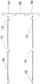
fig. 3 is a view showing the structure of a drive screw.
Detailed Description
In the following, only certain exemplary embodiments are briefly described. As those skilled in the art can appreciate, the described embodiments may be modified in various different ways, without departing from the spirit or scope of the invention. Accordingly, the drawings and description are to be regarded as illustrative in nature, and not as restrictive.
In the description of the present invention, it is to be understood that the terms "central," "longitudinal," "lateral," "length," "width," "thickness," "upper," "lower," "front," "rear," "left," "right," "vertical," "horizontal," "top," "bottom," "inner," "outer," "clockwise," "counterclockwise," "axial," "radial," "circumferential," and the like are used in the orientations and positional relationships indicated in the drawings for convenience in describing the present invention, and are not intended to indicate or imply that the referenced devices or elements must have a particular orientation, be constructed and operated in a particular orientation, and are therefore not to be considered limiting of the present invention.
Embodiments of the present invention will be described in detail below with reference to the accompanying drawings.
As shown in fig. 1~3, the utility model discloses a new trend system's erection equipment, including base 1, 1 bottom of base is rotated and is equipped with the pulley that has brake function, be equipped with the holding tank on the 1 lateral wall of base, the holding tank internal rotation is equipped with vaulting pole 7 that the level set up, the one end of vaulting pole 7 is rotated with the top and the bottom of holding tank and is connected, the other end of vaulting pole 7 is equipped with the sleeve 8 of vertical setting, be equipped with lifter 9 in the sleeve 8, sleeve 8 inner wall and 9 outer walls of lifter are equipped with the internal thread and the external screw thread of mutually supporting respectively, make sleeve 8 and 9 screw-thread fit of lifter, 9 tops of lifter are equipped with rather than coaxial coupling's hand wheel, 9 bottoms of lifter are equipped with and prop seat 10.
Be equipped with fork frame 5 on the base 1, the 5 tops of fork frame are equipped with footstock 3, rotate on the footstock 3 and are equipped with objective table 4, and fork frame 5 goes up and down to drive footstock 3 and objective table 4 go up and down.
The middle of the top surface of the base 1 is provided with a driving groove, two mutually parallel driving screws 12 are arranged in the driving groove in a rotating mode, the driving screws 12 are horizontally arranged, two ends of each driving screw 12 are respectively connected with two inner walls of the driving groove in a rotating mode, a support 11 connected with the driving screws in a rotating mode is arranged in the middle of each driving screw 12, the support 11 is arranged on the driving groove, and the support 11 supports the driving screws 12 to rotate.
The end parts of the two driving screws 12 are provided with driven gears 14 coaxially connected with the driving screws, the driven gears 14 are rotatably arranged in the base 1, a driving gear 15 is rotatably arranged between the two driven gears 14, the driving gear 15 is rotatably connected with the base 1 and meshed with the two driven gears 14, and a motor which is in transmission connection with the driving gear 15 is arranged in the base 1 and serves as a driving source. The motor operates to drive the driving gear 15 to rotate, and the driving gear 15 rotates to drive the two driven gears 14 to synchronously rotate, so that the two driving screws 12 synchronously rotate.
The thread directions of the driving screws 12 on the two sides of the support 11 are opposite, the driving screws 12 on the two sides of the support 11 are respectively provided with a bottom sliding block 13 matched with the thread, the bottom sliding blocks 13 are in sliding connection with the driving grooves, and the two bottom sliding blocks 13 on the driving screws 12 are symmetrically arranged on the two sides of the support 11. The driving screw 12 rotates, and the driving screw 12 and the bottom sliding blocks 13 on the two sides of the support 11 have different thread setting directions, so that the driving screw 12 rotates to drive the two bottom sliding blocks 13 to synchronously move in opposite directions, and the two bottom sliding blocks 13 synchronously approach or leave.
The two ends of the bottom of the two sides of the fork shearing frame 5 are respectively rotatably connected with the two bottom sliders 13 on the driving screws 12, the two driving screws 12 rotate to drive the two ends of the bottom of the fork shearing frame 5 to approach or keep away from each other, and therefore the fork shearing frame 5 is lifted. Two ends of the top of two sides of the fork shearing frame 5 are respectively provided with a top sliding block 6 in a rotating mode, the top sliding blocks 6 are connected with the bottom surface of the top base 3 in a sliding mode, and when the fork shearing frame 5 goes up and down, the top sliding blocks 6 correspondingly slide on the bottom surface of the top base 3.
The base 1 at the edge of the driving groove is provided with a circle of blocking cover 2, the blocking cover 2 is vertically arranged on the base 1 along the edge of the driving groove, and the driving groove and the fork shearing frame 5 are surrounded and blocked at the inner side. The height of the shield 2 is matched with that of the footstock 3, the fork shearing frame 5 is shortened to the maximum extent, and when the footstock 3 is at the lowest height, the top of the shield 2 is contacted with the footstock 3.
When the new trend fan of new trend system, electron purification machine, mix devices such as bellows are installed, place 4 tops on the objective table, rotate vaulting pole 7 and make it break away from the holding tank, rotate the hand wheel, make lifter 9 and 8 screw-thread fit of sleeve descend, support seat 10 support on ground until lifter 9 bottom. The driving source drives the driving gear 15 to rotate, the driving gear 15 drives the two driven gears 14 to synchronously rotate, the two driving screws 12 rotate, two bottom sliders 13 on the driving screws 12 are close to each other, two ends of the bottom of the scissor rack 5 are close to each other, the scissor rack 5 extends upwards to enable the objective table 4 to ascend, a device to be installed of a fresh air system is lifted to the top wall surface, the device is calibrated by moving the base 1 and rotating the objective table 4, the device is fixed at the installation position, and an installer only needs to apply a fixing measure to the device, so that the device is installed.
The utility model discloses convenient operation, the device place on objective table 4 can, objective table 4 rises and to make the device be in wall top department fast, through removing base 1 and rotating objective table 4 and can accomplish the position calibration to the device, improves the operating efficiency, need not artifical lifting device and has reduced artifical intensity of labour, the reduction of operation personnel quantity has also reduced the installation cost.
The above-mentioned embodiment is only the preferred embodiment of the present invention, and is not to the limitation of the technical solution of the present invention, as long as the technical solution can be realized on the basis of the above-mentioned embodiment without creative work, all should be regarded as falling into the protection scope of the right of the present invention.