CN217372011U - A quick clamping frock for processing thin wall work piece - Google Patents
A quick clamping frock for processing thin wall work piece Download PDFInfo
- Publication number
- CN217372011U CN217372011U CN202121731971.5U CN202121731971U CN217372011U CN 217372011 U CN217372011 U CN 217372011U CN 202121731971 U CN202121731971 U CN 202121731971U CN 217372011 U CN217372011 U CN 217372011U
- Authority
- CN
- China
- Prior art keywords
- workpiece
- outer side
- quick clamping
- thin
- evenly
- Prior art date
- Legal status (The legal status is an assumption and is not a legal conclusion. Google has not performed a legal analysis and makes no representation as to the accuracy of the status listed.)
- Expired - Fee Related
Links
Images

Landscapes
- Jigs For Machine Tools (AREA)
Abstract
本实用新型公开了一种用于加工薄壁工件的快速装夹工装,本用于加工薄壁工件的快速装夹工装通过调整调节杆伸入支撑架的长度,进而调整工件侧壁受到的作用力,从工件的侧壁端实现对工件夹紧固定与否,另外,通过压块的固定与否从工件的顶端实现对工件的夹紧固定与否,从而完成对工件的安装固定或拆除。由于调节杆的作用力不是直接作用于工件,而是直接作用在垫块上,再通过垫块传递至工件,从而利用垫块实现了对工件的保护,使工件免受损坏导致变形,通过调整调节杆的作用力大小实现对工件紧固程度的调节,不仅可以使得工件的受力均匀,而且可以对工件在工作台上的安装中心进行适当的调节,使其位于要求的位置上,达到精准安装。
The utility model discloses a quick clamping tool for processing thin-walled workpieces. The quick clamping tooling used for processing thin-walled workpieces adjusts the length of an adjusting rod extending into a support frame, thereby adjusting the effect on the sidewall of the workpiece. Whether the workpiece is clamped and fixed is realized from the side wall end of the workpiece, and whether the workpiece is clamped and fixed from the top of the workpiece is realized by whether the pressure block is fixed or not, so as to complete the installation, fixation or removal of the workpiece. Because the force of the adjusting rod does not directly act on the workpiece, but directly acts on the pad, and then transmits it to the workpiece through the pad, so that the pad can be used to protect the workpiece and prevent the workpiece from being damaged and deformed. The force of the adjustment rod can adjust the degree of tightening of the workpiece, which can not only make the force of the workpiece uniform, but also adjust the installation center of the workpiece on the worktable properly, so that it is located at the required position and achieves precise Install.
Description
技术领域technical field
本实用新型涉及机械加工技术领域,具体为一种用于加工薄壁工件的快速装夹工装。The utility model relates to the technical field of mechanical processing, in particular to a quick clamping tool used for processing thin-walled workpieces.
背景技术Background technique
工件在加工过程中,需要将其固定安装在加工工作台上。目前,固定工件所使用的工装一般只能对工件的下部进行固定,或者只能对工件的其他局部进行固定,而且,工装的作用力会直接作用在工件上,则对于薄壁金属喷管加工工件,由于工件的尺寸比较大,如果只对工件的局部进行固定,就会导致装夹不牢固,而工件在加工过程中,还会受到加工装置的作用力,所以,很容易发生位置的偏移,从而导致加工精度下降。而且,对于薄壁工件,由于其壁薄,如果其在装夹过程中,直接受到工装的作用力,则很容易受到损坏发生变形。During the processing of the workpiece, it needs to be fixedly installed on the processing table. At present, the tooling used to fix the workpiece generally can only fix the lower part of the workpiece, or can only fix other parts of the workpiece. Moreover, the force of the tooling will directly act on the workpiece. The workpiece, because the size of the workpiece is relatively large, if only a part of the workpiece is fixed, the clamping will not be firm, and the workpiece will also be subjected to the force of the processing device during the processing process, so the positional deviation is easy to occur. shift, resulting in a decrease in machining accuracy. Moreover, for thin-walled workpieces, due to their thin walls, if they are directly subjected to the force of the tooling during the clamping process, they are easily damaged and deformed.
实用新型内容Utility model content
鉴于现有技术中所存在的问题,本实用新型公开了一种用于加工薄壁工件的快速装夹工装,采用的技术方案是,包括底座,所述底座的上表面外侧均匀设有立柱,所述立柱为等腰梯形板,所述底座的上表面中部开设有第一卡槽和第二卡槽,所述第一卡槽内配合卡接安装有工件,所述工件的外侧面均匀设有两个支撑圈,两个支撑圈之间均匀设有连接杆,所述连接杆的两端分别与两个支撑圈的外侧面固定连接,位于底端的支撑圈的外侧面底端与立柱的上表面固定连接,位于顶端的支撑圈的外侧面顶端均匀设有支撑耳,所述支撑耳的上表面开设有安装孔,所述工件的外侧面均匀设有垫块,所述垫块的外侧面均匀开设有调节孔,所述垫块的位置与支撑圈的位置对应,所述支撑圈的外侧面均匀设有调节杆,所述调节杆与垫块外侧面的调节孔配合螺纹安装。In view of the problems existing in the prior art, the utility model discloses a quick clamping tool for processing thin-walled workpieces. The upright column is an isosceles trapezoid plate, and the middle part of the upper surface of the base is provided with a first clamping groove and a second clamping groove, the first clamping groove is fitted with a workpiece, and the outer side of the workpiece is evenly arranged. There are two support rings, and connecting rods are evenly arranged between the two support rings. The two ends of the connecting rods are respectively fixedly connected with the outer sides of the two support rings. The upper surface is fixedly connected, the top of the outer side of the support ring at the top is evenly provided with support ears, the upper surface of the support ears is provided with mounting holes, the outer side of the workpiece is evenly provided with pads, and the outer Adjusting holes are evenly opened on the side surface, the position of the cushion block corresponds to the position of the support ring, and the outer side surface of the support ring is evenly provided with adjustment rods, and the adjustment rods are threadedly installed with the adjustment holes on the outer side of the cushion block.
作为本实用新型的一种优选技术方案,还包括压块,所述压块均匀设于工件的上表面,所述压块为矩形板,所述压块的上表面的螺孔内设有固定螺栓,所述固定螺栓与支撑耳上表面的安装孔配合螺纹安装,通过压块与支撑耳的配合安装可完成对工件的夹紧。As a preferred technical solution of the present invention, it also includes a pressure block, which is evenly arranged on the upper surface of the workpiece, the pressure block is a rectangular plate, and the screw holes on the upper surface of the pressure block are provided with fixing blocks. Bolts, the fixing bolts are fitted with the mounting holes on the upper surface of the support ears for threaded installation, and the clamping of the workpiece can be completed through the cooperative installation of the pressing blocks and the support ears.
作为本实用新型的一种优选技术方案,所述垫块为橡胶板,所述垫块于工件的外侧面竖向和横向间隔排列,通过为橡胶板的垫块可对工件进行保护,使工件免受损坏导致变形。As a preferred technical solution of the present invention, the spacer is a rubber plate, and the spacer is arranged vertically and horizontally on the outer side of the workpiece. Protected from damage resulting in deformation.
作为本实用新型的一种优选技术方案,还包括定位环,所述定位环设于第二卡槽的内部,通过定位环可使工件与底板的配合安装更为快速。As a preferred technical solution of the present invention, a positioning ring is further included, the positioning ring is arranged inside the second clamping groove, and the matching and installation of the workpiece and the bottom plate can be made faster by the positioning ring.
作为本实用新型的一种优选技术方案,所述底座的上表面均匀开设有固定槽和固定孔,所述固定槽和固定孔错位设置,通过固定槽和固定孔可使底座进行快速的固定安装及拆卸。As a preferred technical solution of the present invention, the upper surface of the base is evenly provided with fixing grooves and fixing holes, the fixing grooves and fixing holes are arranged in a dislocation, and the base can be quickly fixed and installed through the fixing grooves and fixing holes and disassembly.
本实用新型的有益效果:本实用新型通过调整调节杆伸入支撑架的长度,进而调整工件侧壁受到的作用力,从工件的侧壁端实现对工件夹紧固定与否,另外,通过压块的固定与否从工件的顶端实现对工件的夹紧固定与否,从而完成对工件的安装固定或拆除。由于调节杆的作用力不是直接作用于工件,而是直接作用在垫块上,再通过垫块传递至工件,从而利用垫块实现了对工件的保护,使工件免受损坏导致变形,通过调整调节杆的作用力大小实现对工件紧固程度的调节,不仅可以使得工件的受力均匀,而且可以对工件在工作台上的安装中心进行适当的调节,使其位于要求的位置上,达到精准安装。The beneficial effects of the utility model: the utility model adjusts the length of the adjusting rod extending into the support frame, and then adjusts the force on the side wall of the workpiece, and realizes whether the workpiece is clamped and fixed from the side wall end of the workpiece. Whether the block is fixed or not realizes the clamping and fixing of the workpiece from the top of the workpiece, so as to complete the installation, fixing or removal of the workpiece. Because the force of the adjusting rod does not directly act on the workpiece, but directly acts on the pad, and then transmits it to the workpiece through the pad, so that the pad is used to protect the workpiece and prevent the workpiece from being damaged and deformed. The force of the adjusting rod realizes the adjustment of the tightening degree of the workpiece, which can not only make the force of the workpiece uniform, but also adjust the installation center of the workpiece on the worktable appropriately, so that it is located at the required position and achieves precise Install.
附图说明Description of drawings
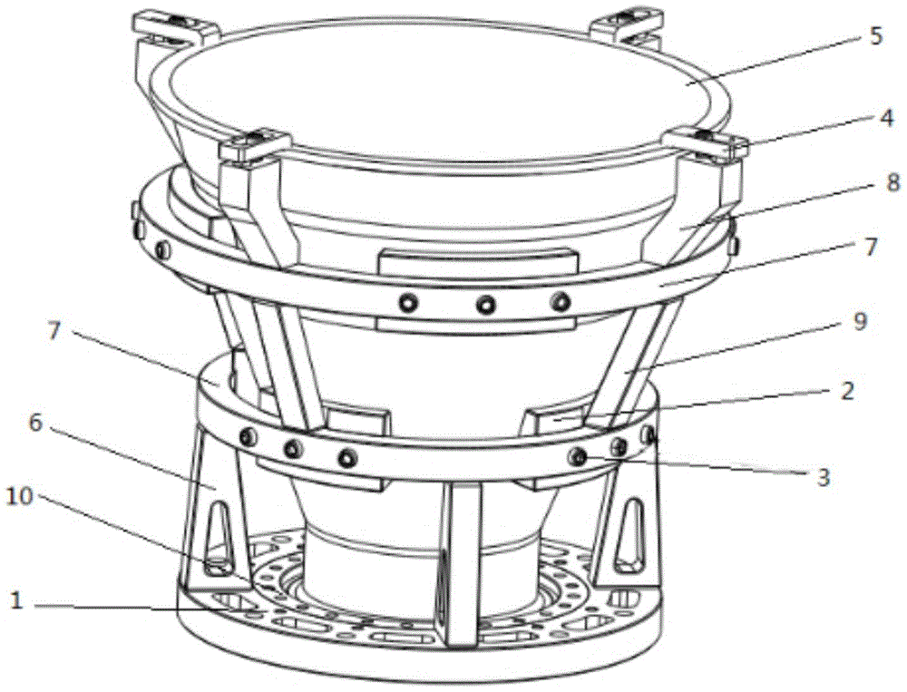
图1为本实用新型结构示意图;Fig. 1 is the structural representation of the utility model;
图中:1底座、2垫块、3调节杆、4压块、5工件、6立柱、7支撑圈、8支撑耳、9连接杆、10定位环。In the picture: 1 base, 2 spacers, 3 adjustment rods, 4 pressure blocks, 5 workpieces, 6 columns, 7 support rings, 8 support ears, 9 connecting rods, 10 positioning rings.
具体实施方式Detailed ways
实施例1Example 1
如图1所示,本实用新型公开了一种用于加工薄壁工件的快速装夹工装,采用的技术方案是,包括底座1,底座1的上表面外侧均匀设有立柱6,立柱6为等腰梯形板,底座1的上表面中部开设有第一卡槽和第二卡槽,第一卡槽内配合卡接安装有工件5,工件5的外侧面均匀设有两个支撑圈7,两个支撑圈7之间均匀设有连接杆9,连接杆9的两端分别与两个支撑圈7的外侧面固定连接,位于底端的支撑圈7的外侧面底端与立柱6的上表面固定连接,位于顶端的支撑圈7的外侧面顶端均匀设有支撑耳8,支撑耳8的上表面开设有安装孔,工件5的外侧面均匀设有垫块2,垫块2的外侧面均匀开设有调节孔,垫块2的位置与支撑圈7的位置对应,支撑圈的外侧面均匀设有调节杆3,调节杆3与垫块2外侧面的调节孔配合螺纹安装,通过将工装5放在支撑圈7的内部,且使垫块2的内壁可以贴合在工件5的外壁上,然后增大调节杆3伸入支撑圈7的长度,使调节杆3的前端带动垫块2靠近并顶紧工件5的外壁,当达到预定要求时,则固定调节杆3,从工件5侧壁端实现对工件5的夹紧固定,将压块4放置好,其一端位于支撑耳8的顶端并通过固定螺栓固定,其另一端位于工件5的上边沿上,由于压块4固定不动,则可以通过压块4从工件5的顶端实现对工件5的固定,加工完毕后,需要从工装上拆卸时,可以反方向调整调节杆3,减小调节杆3伸入支撑圈7的长度,使调节杆3的前端对垫块2的作用力减小,工件5的侧壁不再被顶紧,垫块2的内壁和工件5外壁之间出现一定的空隙,另外,通过拆卸压块4去除对工件5上边沿的固定作用。最后,当侧壁端和顶端的固定作用力都去除,工件5不再受到工装作用力后,可以将工件5从工装内取出,实现工件5从工装上的拆卸。As shown in FIG. 1 , the utility model discloses a quick clamping tool for processing thin-walled workpieces. The technical solution adopted is that it includes a
作为本实用新型的一种优选技术方案,还包括压块4,压块4均匀设于工件5的上表面,压块4为矩形板,压块4的上表面的螺孔内设有固定螺栓,固定螺栓与支撑耳8上表面的安装孔配合螺纹安装,通过压块4与支撑耳8的配合安装可完成对工件的夹紧,进而可使本用于加工薄壁工件的快速装夹工装快速的对工件进行安装固定及拆除。As a preferred technical solution of the present invention, it also includes a
作为本实用新型的一种优选技术方案,垫块2为橡胶板,垫块2于工件5的外侧面竖向和横向间隔排列,通过为橡胶板的垫块2可对工件进行保护,使工件免受损坏导致变形,从而使本用于加工薄壁工件的快速装夹工装的装夹效果得到保障。As a preferred technical solution of the present utility model, the
作为本实用新型的一种优选技术方案,还包括定位环10,定位环10设于第二卡槽的内部,通过定位环10可使工件5与底板1的配合安装更为快速,从而使本用于加工薄壁工件的快速装夹工装对工件的装夹效率得到提升。As a preferred technical solution of the present invention, a
作为本实用新型的一种优选技术方案,底座1的上表面均匀开设有固定槽和固定孔,固定槽和固定孔错位设置,通过固定槽和固定孔可使底座1进行快速的固定安装及拆卸,从而使本用于加工薄壁工件的快速装夹工装的使用更为便捷及稳定。As a preferred technical solution of the present invention, the upper surface of the
本实用新型的工作原理:在安装工件5时,首先将工装5放在支撑圈7的内部,且使垫块2的内壁可以贴合在工件5的外壁上,然后增大调节杆3伸入支撑圈7的长度,使调节杆3的前端带动垫块2靠近并顶紧工件5的外壁,当达到预定要求时,则固定调节杆3,从工件5侧壁端实现对工件5的夹紧固定,将压块4放置好,其一端位于支撑耳8的顶端并通过固定螺栓固定,其另一端位于工件5的上边沿上,由于压块4固定不动,则可以通过压块4从工件5的顶端实现对工件5的固定,加工完毕后,需要从工装上拆卸时,可以反方向调整调节杆3,减小调节杆3伸入支撑圈7的长度,使调节杆3的前端对垫块2的作用力减小,工件5的侧壁不再被顶紧,垫块2的内壁和工件5外壁之间出现一定的空隙,另外,通过拆卸压块4去除对工件5上边沿的固定作用。最后,当侧壁端和顶端的固定作用力都去除,工件5不再受到工装作用力后,可以将工件5从工装内取出,实现工件5从工装上的拆卸。The working principle of the utility model: when installing the
本实用新型涉及的电路连接为本领域技术人员采用的惯用手段,可通过有限次试验得到技术启示,属于广泛使用的现有技术。The circuit connection involved in the present invention is a conventional means adopted by those skilled in the art, and technical inspiration can be obtained through limited trials, and belongs to the widely used prior art.
本文中未详细说明的部件为现有技术。Components not detailed herein are prior art.
上述虽然对本实用新型的具体实施例作了详细说明,但是本实用新型并不限于上述实施例,在本领域普通技术人员所具备的知识范围内,还可以在不脱离本实用新型宗旨的前提下做出各种变化,而不具备创造性劳动的修改或变形仍在本实用新型的保护范围以内。Although the specific embodiments of the present utility model have been described in detail above, the present utility model is not limited to the above-mentioned embodiments, and within the scope of knowledge possessed by those of ordinary skill in the art, it is also possible to do so without departing from the purpose of the present utility model. Various changes, modifications or deformations without creative work are still within the protection scope of the present invention.
Claims (5)
Priority Applications (1)
| Application Number | Priority Date | Filing Date | Title |
|---|---|---|---|
| CN202121731971.5U CN217372011U (en) | 2021-07-28 | 2021-07-28 | A quick clamping frock for processing thin wall work piece |
Applications Claiming Priority (1)
| Application Number | Priority Date | Filing Date | Title |
|---|---|---|---|
| CN202121731971.5U CN217372011U (en) | 2021-07-28 | 2021-07-28 | A quick clamping frock for processing thin wall work piece |
Publications (1)
| Publication Number | Publication Date |
|---|---|
| CN217372011U true CN217372011U (en) | 2022-09-06 |
Family
ID=83084056
Family Applications (1)
| Application Number | Title | Priority Date | Filing Date |
|---|---|---|---|
| CN202121731971.5U Expired - Fee Related CN217372011U (en) | 2021-07-28 | 2021-07-28 | A quick clamping frock for processing thin wall work piece |
Country Status (1)
| Country | Link |
|---|---|
| CN (1) | CN217372011U (en) |
Cited By (1)
| Publication number | Priority date | Publication date | Assignee | Title |
|---|---|---|---|---|
| CN116460620A (en) * | 2023-04-20 | 2023-07-21 | 中国工程物理研究院激光聚变研究中心 | Clamping device and clamping method for inner surface processing of high-steep thin-walled components |
-
2021
- 2021-07-28 CN CN202121731971.5U patent/CN217372011U/en not_active Expired - Fee Related
Cited By (1)
| Publication number | Priority date | Publication date | Assignee | Title |
|---|---|---|---|---|
| CN116460620A (en) * | 2023-04-20 | 2023-07-21 | 中国工程物理研究院激光聚变研究中心 | Clamping device and clamping method for inner surface processing of high-steep thin-walled components |
Similar Documents
| Publication | Publication Date | Title |
|---|---|---|
| CN207746748U (en) | A kind of thin wall curved guide clamp for machining | |
| CN208034155U (en) | Stable workpiece clamping fixture | |
| CN105252310A (en) | Box machining device | |
| CN214770474U (en) | Large-scale annular thin wall casing part precision finishing fixing device | |
| CN111890086A (en) | A clamping device for wind power gearbox cover | |
| CN208051448U (en) | A kind of fixture for workpiece to be processed to be clamped | |
| CN205166090U (en) | Wire -electrode cutting frock of plane molybdenum target material | |
| CN217495210U (en) | A simple positioning and clamping device for 3D printer working platform | |
| CN114603498A (en) | A kind of quartz bracket clamping fixture and using method thereof | |
| WO2021097906A1 (en) | Surface treatment device for metal stamping part | |
| CN207139373U (en) | A kind of single-station grip device | |
| CN104589090B (en) | A kind of tapping clamp | |
| CN222680194U (en) | CNC numerical control mills part processing positioning fixture | |
| CN219819417U (en) | Clamping tool | |
| CN223057226U (en) | Machining cutting positioning device | |
| CN220839076U (en) | Sheet part machining clamp | |
| CN206779927U (en) | Specific jig | |
| CN105903846B (en) | An auxiliary blanking fixture | |
| CN221936527U (en) | A high-efficiency mold changing fixture | |
| CN218947434U (en) | A clamping device for removing the cover of an optical device | |
| CN222958085U (en) | Large-scale thin wall bent plate frock | |
| CN221312534U (en) | Fixing device is used in engine support processing | |
| CN210046225U (en) | Welding tooling | |
| CN218109089U (en) | A mold external fixing device | |
| CN223531122U (en) | A novel flatness adjustment structure |
Legal Events
| Date | Code | Title | Description |
|---|---|---|---|
| GR01 | Patent grant | ||
| GR01 | Patent grant | ||
| CF01 | Termination of patent right due to non-payment of annual fee | ||
| CF01 | Termination of patent right due to non-payment of annual fee |
Granted publication date: 20220906 |