CN217369900U - Building fastener forming device that buckles - Google Patents
Building fastener forming device that buckles Download PDFInfo
- Publication number
- CN217369900U CN217369900U CN202220788634.8U CN202220788634U CN217369900U CN 217369900 U CN217369900 U CN 217369900U CN 202220788634 U CN202220788634 U CN 202220788634U CN 217369900 U CN217369900 U CN 217369900U
- Authority
- CN
- China
- Prior art keywords
- support rod
- bending
- bending roller
- construction
- fixing block
- Prior art date
- Legal status (The legal status is an assumption and is not a legal conclusion. Google has not performed a legal analysis and makes no representation as to the accuracy of the status listed.)
- Active
Links
Images

Landscapes
- Conveying And Assembling Of Building Elements In Situ (AREA)
Abstract
本实用新型涉及一种建筑紧固件弯折成型装置,属于建筑施工机械技术领域。所述的建筑紧固件弯折成型装置包括底板、驱动电机、弯折辊、固定块、支撑杆;所述的驱动电机固定安装在底板上,弯折辊连接驱动电机转动轴,弯折辊上安装有固定块,固定块为L型块,固定块一边的端部固定在弯折辊上,另一边与弯折辊平行设置,支撑杆通过支撑杆安装架安装在底板上,支撑杆与弯折辊平行设置,支撑杆的底边高于弯折辊的顶边。本实用新型采用驱动电机驱动弯折辊、固定块固定建筑紧固件的端部、支撑杆支撑建筑紧固件的另一端,通过弯折辊的转动带动建筑紧固件转动弯折成型,节约了施工时间,降低了施工人员劳动强度,提高了建筑紧固件弯折的效率。

The utility model relates to a bending and forming device for a building fastener, which belongs to the technical field of building construction machinery. The construction fastener bending and forming device includes a base plate, a driving motor, a bending roller, a fixing block and a support rod; the driving motor is fixedly installed on the base plate, the bending roller is connected to the rotating shaft of the driving motor, and the bending roller A fixing block is installed on the upper part. The fixing block is an L-shaped block. One end of the fixing block is fixed on the bending roller, and the other side is parallel to the bending roller. The support rod is installed on the bottom plate through the support rod mounting bracket. The bending rollers are arranged in parallel, and the bottom edge of the support rod is higher than the top edge of the bending roller. The utility model adopts the driving motor to drive the bending roller, the fixing block to fix the end of the construction fastener, and the support rod to support the other end of the construction fastener. The construction time is shortened, the labor intensity of construction personnel is reduced, and the bending efficiency of building fasteners is improved.
Description
技术领域technical field
本实用新型属于建筑施工机械技术领域,具体的说,涉及一种建筑紧固件弯折成型装置。The utility model belongs to the technical field of building construction machinery, in particular to a bending and forming device for building fasteners.
背景技术Background technique
现有建筑紧固件弯折采用圆形物体通过人力进行弯折,这样的操作方式费时费力,操作困难,刚度较大的建筑紧固件难以通过人力进行弯折,建筑紧固件弯折的效率低下。The existing building fasteners are bent by using circular objects by manpower. Such an operation method is time-consuming and laborious, and the operation is difficult. Building fasteners with high rigidity are difficult to bend by manpower. low efficiency.
因此,有必要提供一种建筑紧固件弯折成型装置,节约施工时间,降低施工人员劳动强度,提高建筑紧固件弯折的效率。Therefore, it is necessary to provide a bending and forming device for building fasteners, which saves construction time, reduces the labor intensity of construction personnel, and improves the bending efficiency of building fasteners.
实用新型内容Utility model content
为了克服背景技术中存在的建筑紧固件弯折费时费力,操作困难的问题,本实用新型提供了一种建筑紧固件弯折成型装置,节约了施工时间,降低了施工人员劳动强度,提高了建筑紧固件弯折的效率。In order to overcome the problems of time-consuming, labor-intensive and difficult operation of building fasteners in the background art, the utility model provides a bending and forming device for building fasteners, which saves construction time, reduces the labor intensity of construction personnel, and improves the The efficiency of the bending of construction fasteners.
为实现上述目的,本实用新型是通过如下技术方案实现的:To achieve the above object, the present invention is achieved through the following technical solutions:
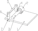
本实用新型提供了一种建筑紧固件弯折成型装置,包括底板1、驱动电机2、弯折辊3、固定块4、支撑杆5;所述的驱动电机2固定安装在底板1上,弯折辊3连接驱动电机2的转动轴,弯折辊3上安装有固定块4,固定块4为L型块,固定块4一边的端部固定在弯折辊3上,另一边与弯折辊3平行设置,支撑杆5通过支撑杆安装架6安装在底板1上,支撑杆5与弯折辊3平行设置,支撑杆5的底边高于弯折辊3的顶边。The utility model provides a bending and forming device for building fasteners, comprising a base plate 1, a driving motor 2, a
作为优选,所述的支撑杆5转动安装在支撑杆安装架6上。Preferably, the
作为优选,所述的支撑杆安装架6滑动嵌套在底板1上,通过紧固螺栓7固定。Preferably, the support
本实用新型的有益效果:The beneficial effects of the present utility model:
本实用新型采用驱动电机驱动弯折辊、固定块固定建筑紧固件的端部、支撑杆支撑建筑紧固件的另一端,通过弯折辊的转动带动建筑紧固件转动弯折成型,节约了施工时间,降低了施工人员劳动强度,提高了建筑紧固件弯折的效率。The utility model adopts the driving motor to drive the bending roller, the fixing block to fix the end of the construction fastener, and the support rod to support the other end of the construction fastener. The construction time is shortened, the labor intensity of construction personnel is reduced, and the bending efficiency of building fasteners is improved.
附图说明Description of drawings
图1是本实用新型的结构示意图;Fig. 1 is the structural representation of the present utility model;
图2是本实用新型另一角度的结构示意图。FIG. 2 is a schematic structural diagram of another angle of the present invention.
图中,1-底板、2-驱动电机、3-弯折辊、4-固定块、5-支撑杆、6-支撑杆安装架、7-紧固螺栓。In the figure, 1-base plate, 2-drive motor, 3-bending roller, 4-fixing block, 5-support rod, 6-support rod mounting frame, 7-fastening bolt.
具体实施方式Detailed ways
为了使本实用新型的目的、技术方案和有益效果更加清楚,下面将结合附图,对本实用新型的优选实施例进行详细的说明,以方便技术人员理解。In order to make the objectives, technical solutions and beneficial effects of the present utility model clearer, the preferred embodiments of the present utility model will be described in detail below with reference to the accompanying drawings, so as to facilitate the understanding of the skilled person.
如图1-2所示,所述的建筑紧固件弯折成型装置包括底板1、驱动电机2、弯折辊3、固定块4、支撑杆5;所述的驱动电机2固定安装在底板1上,弯折辊3连接驱动电机2的转动轴,弯折辊3上安装有固定块4,固定块4为L型块,固定块4一边的端部固定在弯折辊3上,另一边与弯折辊3平行设置,支撑杆5通过支撑杆安装架6安装在底板1上,支撑杆5与弯折辊3平行设置,支撑杆5的底边高于弯折辊3的顶边;将建筑紧固件的一端卡合在固定块4处,建筑紧固件处于弯折辊3上表面和支撑杆5下表面之间,启动驱动电机2使驱动电机2带动弯折辊3转动,弯折辊3带动建筑紧固件产生弯折,建筑紧固件在固定块4的固定作用下贴合弯折辊3弯折卷圈成型,另一个支撑点在支撑杆5上,操作人员只用手动稳定建筑紧固件便可以轻松的将建筑紧固件弯折,解决了刚度较大的建筑紧固件难以通过人力进行弯折的问题。As shown in Figures 1-2, the described building fastener bending and forming device includes a base plate 1, a drive motor 2, a
所述的支撑杆5转动安装在支撑杆安装架6上,减少支撑杆5和建筑紧固件之间的摩擦,减少支撑杆5的磨损。The
所述的支撑杆安装架6滑动嵌套在底板1上,通过紧固螺栓7固定,根据建筑紧固件的直径大小,可以通过紧固螺栓7调节支撑杆安装架6的位置,以调整支撑杆5的高度,保证支撑杆5能够平稳的作为建筑紧固件的支撑点。The support
本实用新型采用驱动电机2驱动弯折辊3、固定块4固定建筑紧固件的端部、支撑杆5支撑建筑紧固件的另一端,通过弯折辊3的转动带动建筑紧固件转动弯折成型,节约了施工时间,降低了施工人员劳动强度,提高了建筑紧固件弯折的效率。The utility model adopts the driving motor 2 to drive the
最后说明的是,以上优选实施例仅用于说明本实用新型的技术方案而非限制,尽管通过上述优选实施例已经对本实用新型进行了详细的描述,但本领域技术人员应当理解,可以在形式上和细节上对其作出各种各样的改变,而不偏离本实用新型权利要求书所限定的范围。Finally, it should be noted that the above preferred embodiments are only used to illustrate the technical solutions of the present utility model rather than limitations. Although the present utility model has been described in detail through the above preferred embodiments, those skilled in the art should Various changes can be made in the above and in the details without departing from the scope of the present invention as defined by the claims of the present invention.
Claims (3)
Priority Applications (1)
| Application Number | Priority Date | Filing Date | Title |
|---|---|---|---|
| CN202220788634.8U CN217369900U (en) | 2022-04-07 | 2022-04-07 | Building fastener forming device that buckles |
Applications Claiming Priority (1)
| Application Number | Priority Date | Filing Date | Title |
|---|---|---|---|
| CN202220788634.8U CN217369900U (en) | 2022-04-07 | 2022-04-07 | Building fastener forming device that buckles |
Publications (1)
| Publication Number | Publication Date |
|---|---|
| CN217369900U true CN217369900U (en) | 2022-09-06 |
Family
ID=83105649
Family Applications (1)
| Application Number | Title | Priority Date | Filing Date |
|---|---|---|---|
| CN202220788634.8U Active CN217369900U (en) | 2022-04-07 | 2022-04-07 | Building fastener forming device that buckles |
Country Status (1)
| Country | Link |
|---|---|
| CN (1) | CN217369900U (en) |
-
2022
- 2022-04-07 CN CN202220788634.8U patent/CN217369900U/en active Active
Similar Documents
| Publication | Publication Date | Title |
|---|---|---|
| CN209298708U (en) | A kind of isolator operating mechanism installation auxiliary device | |
| CN210788709U (en) | Steel plate bending device | |
| CN209965881U (en) | Rotary turntable driven by friction at side part of track | |
| CN218448421U (en) | Base station antenna installation adjusting device | |
| CN219151207U (en) | Open flat-bed machine with levelling device | |
| CN201913598U (en) | Flange high-pressure oil pump gear disassembling fixture | |
| CN213944392U (en) | Waveform guardrail plate straightening machine for highway | |
| CN214197133U (en) | Belt tensioning device | |
| CN210150080U (en) | Aluminum profile traction machine | |
| CN221911839U (en) | Water pump installation overhauls support | |
| CN218134222U (en) | Galvanized flat iron bending forming device | |
| CN223344888U (en) | A concrete drainage pipe hanger | |
| CN219142479U (en) | Intensity detection device for color steel plate production | |
| CN220033804U (en) | Oil delivery pipe installing support | |
| CN221295658U (en) | Novel paying-off device | |
| CN217344203U (en) | Steel construction butt welding adjusting device | |
| CN221116274U (en) | Electric fast belt conveyor | |
| CN217251847U (en) | An angle-adjustable pipe bender for processing front car brackets | |
| CN222316179U (en) | Stable pipeline support and hanger | |
| CN223659688U (en) | A high-efficiency steel structure hoisting equipment | |
| CN222437565U (en) | A non-disassembly flaw detector fixing device | |
| CN223097832U (en) | Aluminium alloy coalignment | |
| CN222664588U (en) | Belt deviation corrector with adjustable angle | |
| CN212794414U (en) | a belt sander | |
| CN222748393U (en) | Waterproofing membrane intensity detection device |
Legal Events
| Date | Code | Title | Description |
|---|---|---|---|
| GR01 | Patent grant | ||
| GR01 | Patent grant | ||
| PE01 | Entry into force of the registration of the contract for pledge of patent right |
Denomination of utility model: A bending and forming device for building fasteners Effective date of registration: 20231218 Granted publication date: 20220906 Pledgee: Shenzhen Deyuan Commercial Factoring Co.,Ltd. Pledgor: SINOHYDRO BUREAU 14 Co.,Ltd. Registration number: Y2023980072201 |
|
| PE01 | Entry into force of the registration of the contract for pledge of patent right | ||
| PC01 | Cancellation of the registration of the contract for pledge of patent right |
Granted publication date: 20220906 Pledgee: Shenzhen Deyuan Commercial Factoring Co.,Ltd. Pledgor: SINOHYDRO BUREAU 14 Co.,Ltd. Registration number: Y2023980072201 |
|
| PC01 | Cancellation of the registration of the contract for pledge of patent right |