CN217354234U - Retractable cat ladder - Google Patents
Retractable cat ladder Download PDFInfo
- Publication number
- CN217354234U CN217354234U CN202222079280.2U CN202222079280U CN217354234U CN 217354234 U CN217354234 U CN 217354234U CN 202222079280 U CN202222079280 U CN 202222079280U CN 217354234 U CN217354234 U CN 217354234U
- Authority
- CN
- China
- Prior art keywords
- mounting box
- ladder
- mounting
- ladder stand
- block
- Prior art date
- Legal status (The legal status is an assumption and is not a legal conclusion. Google has not performed a legal analysis and makes no representation as to the accuracy of the status listed.)
- Active
Links
- 241000282326 Felis catus Species 0.000 title claims description 49
- 230000009193 crawling Effects 0.000 claims description 64
- 238000009434 installation Methods 0.000 claims description 7
- 238000001125 extrusion Methods 0.000 description 6
- 230000009286 beneficial effect Effects 0.000 description 3
- 238000013459 approach Methods 0.000 description 2
- 230000009194 climbing Effects 0.000 description 2
- 230000006835 compression Effects 0.000 description 2
- 238000007906 compression Methods 0.000 description 2
- 230000002349 favourable effect Effects 0.000 description 2
- 238000003780 insertion Methods 0.000 description 2
- 230000037431 insertion Effects 0.000 description 2
- 238000000034 method Methods 0.000 description 2
- 238000013508 migration Methods 0.000 description 2
- 230000005012 migration Effects 0.000 description 2
- 229910000831 Steel Inorganic materials 0.000 description 1
- 238000012423 maintenance Methods 0.000 description 1
- 238000002360 preparation method Methods 0.000 description 1
- 238000012545 processing Methods 0.000 description 1
- 238000000926 separation method Methods 0.000 description 1
- 239000010959 steel Substances 0.000 description 1
Images


Landscapes
- Ladders (AREA)
Abstract
The utility model discloses a retractable ladder stand, which belongs to the technical field of ladder stands and comprises a first ladder stand fixedly arranged on a wall body and a second ladder stand arranged on the first ladder stand in a sliding way, wherein a mounting box is fixedly arranged at the bottom of the back surface of the first ladder stand, symmetrical sockets are arranged at the bottom of the mounting box, symmetrical plug boards are fixedly arranged at the bottom of the back surface of the second ladder stand, plug pin ports are arranged on the plug boards, a fixing mechanism for fixing the plug boards and the second ladder stand is arranged in the mounting box, the fixing mechanism comprises symmetrical movable blocks which are arranged in the mounting box in a sliding way, plug pins which are fixedly arranged at one side of the movable blocks close to the sockets, and symmetrical mounting plates which are fixedly arranged in the mounting box, a lock is additionally arranged between the two ladder stands to ensure that a person with leisure can not use the ladder stand at will without the help of other ladder stands, the practicability is strong.
Description
Technical Field
The utility model relates to a cat ladder technical field especially relates to a retractable cat ladder.
Background
Use is overhauld as the roofing, and the cat ladder all can be seen at all kinds of buildings, and traditional cat ladder generally utilizes the angle steel preparation, uses the cat ladder for avoiding the miscellaneous people of idle, generally designs cat ladder terrain clearance 1.8m, need increase in addition during the maintenance and remove the cat ladder cooperation and carry out the operation, and is more troublesome, if meet emergency, still can influence the processing speed of incident, so need one kind avoid the miscellaneous people of idle to use at will and can directly utilize the telescopic cat ladder that the cat ladder carried out the operation.
SUMMERY OF THE UTILITY MODEL
The utility model provides a pair of retractable cat ladder has solved both can avoid the idle miscellaneous people to use at will, can directly utilize the cat ladder to carry out the problem of operation again.
In order to solve the technical problem, the utility model adopts the following technical scheme:
a telescopic ladder stand comprises a first ladder stand fixedly arranged on a wall body and a second ladder stand arranged on the first ladder stand in a sliding manner; the bottom of the back surface of the first crawling ladder is fixedly provided with a mounting box, the bottom side wall of the mounting box is provided with two sockets, the two sockets are arranged in axial symmetry by taking a median line of the bottom side wall of the mounting box as an axis, the bottom of the back surface of the second crawling ladder is fixedly provided with two plug boards, and the plug boards and the sockets are in one-to-one correspondence and are matched for use; and a fixing mechanism for fixing the inserting plate and the first ladder stand is arranged in the mounting box.
When an operator needs to slide the second crawling ladder into the first crawling ladder for fixing after using the second crawling ladder, the operator stands at the back of the second crawling ladder and then directly upwards pushes the second crawling ladder, so that the second crawling ladder upwards slides on the first crawling ladder to insert the inserting plate at the bottom of the second crawling ladder into the inserting hole in the mounting box, and the inserting plate and the first crawling ladder are fixed through the fixing mechanism in the mounting box. When cat ladder two uses, operating personnel carries out the unblock to the picture peg through fixed establishment, alright make cat ladder two go up the lapse on cat ladder one, extend the cat ladder, this retractable cat ladder has increased the tool to lock between two parts cat ladder, guarantees that the idle miscellaneous people can not use the cat ladder at will, and the practicality is strong.
As preferred, fixed establishment is including two movable blocks and two of slip setting in the mounting box the movable block uses the mounting box bottom side wall median line to set up as the axial symmetry, fixed mounting is close to the bolt of socket one side at the movable block, two mounting panels and two mounting panels of fixed mounting in the mounting box use the mounting box bottom side wall median line to set up as the axial symmetry, fixed mounting is close to the fly leaf of socket one side at every movable block, fixed mounting is fixed spring between mounting panel and fly leaf, set up the driving piece that is used for driving bolt horizontal migration on the mounting box and set up the bolt mouth on two picture peg opposite flank, the bolt mouth uses with bolt one-to-one and cooperation.
Adopt above-mentioned scheme, start the driving piece, the driving piece drives the fixed spring and the fly leaf of movable block on the pulling mounting panel in the mounting panel and keeps away from each other, the movable block keeps away from each other and makes in inserting the bolt on the picture peg with the bolt of movable block fixed mounting, fix picture peg and cat ladder two, when cat ladder two uses, start the driving piece, it is close to each other to drive the movable block through the restoring force of fixed spring and fly leaf, make the bolt on the movable block break away from the bolt mouth on the picture peg, alright make cat ladder two slide from top to bottom on cat ladder one, move about to cat ladder two and extend, moreover, the steam generator is simple in structure, and convenient operation.
Preferably, the driving piece comprises a sliding groove formed in the side wall of the top of the mounting box and a supporting block arranged in the sliding groove in a sliding mode, the side face of the supporting block is attached to the side face of the movable block, and the attaching faces of the supporting block and the movable block are both inclined planes. By adopting the scheme, the operator presses the abutting block downwards, the side face of the abutting block is attached to the side face of the movable block, and the abutting face of the abutting block and the movable block is arranged to be an inclined face, so that the abutting block pushes the movable block to pull the fixed spring and the movable plate on the mounting plate away from each other in the mounting box, otherwise, the operator moves the abutting block upwards, and the movable block is driven to be close to each other through the restoring force of the fixed spring and the movable plate, thereby being beneficial to realizing the driving of the bolt.
Preferably, be provided with on the mounting box and be used for carrying out spacing stop gear to supporting the piece, stop gear is including offering on supporting a leading flank and trailing flank and coaxial spacing mouthful, offer on the spout lateral wall with spacing mouthful one-to-one and with spacing mouthful coaxial mounting mouth, fixed mounting at the intraoral spacing spring of mounting and the stopper that slides and set up in the mounting mouth and with spacing spring end fixed mounting, the stopper sets up to the cambered surface with spacing mouthful binding face the two.
Adopt above-mentioned scheme, fix the back to cat ladder two, need fix to supporting the piece, support the stopper that the piece contradicted on the spout when the lapse in the spout for the stopper receives in extrusion force compression spacing spring contracts to the installing port, when the bolt inserts the bolt mouth completely in, support spacing mouthful on the piece just to the installing port on the spout, make the stopper card go into spacing mouthful through the restoring force of spacing spring, fix to supporting the piece, improve the stability after cat ladder two are fixed.
Preferably, the side wall of the bottom of the mounting box is provided with a slide way, the bottom of the abutting block is fixedly provided with a push rod, and the push rod is in sliding fit with the slide way.
Adopt above-mentioned scheme, when needs carry out unblock downwardly movable to cat ladder two and extend, operating personnel only need promote the push rod in the mounting box bottom slide, and the push rod upwards moves in the mounting box and drives rather than fixed mounting's the piece of supporting upwards moving on the spout, and the stopper receives the extrusion force and breaks away from spacing mouthful in getting into the mounting box, is favorable to realizing the drive to supporting the piece, can not operate the idle miscellaneous people of push rod setting in the mounting box, just can not use the cat ladder.
As preferred, picture peg size and socket size match, bolt size and bolt mouth size match.
By adopting the scheme, the stability of the first crawling ladder and the second crawling ladder in the fixing process is improved.
Preferably, a plurality of jacks uniformly distributed in the length direction of the second crawling ladder are formed in one vertical side face of the second crawling ladder, an installation block is rotatably installed at the bottom of the side edge of the first crawling ladder close to the jacks, a fixing pin is arranged on one side of the installation block close to the jacks, and the fixing pin is matched with the jacks for use.
By adopting the scheme, when the second crawling ladder moves to the designated position on the first crawling ladder, the fixing pins on the slidable mounting blocks are inserted into the insertion holes on the two sides of the crawling ladder, so that the second crawling ladder can be locked after being pulled out.
Compared with the prior art, the utility model discloses following beneficial effect has at least:
1. the device is through setting up mounting box, socket, picture peg, bolt mouth, movable block, bolt, mounting panel, fixed spring, fly leaf, driving piece, spout and supporting the cooperation work between the piece, realizes simple and easy fixed and the separation to cat ladder one and cat ladder two, and the miscellaneous people of idle person of being not convenient for simultaneously operate, guarantees that the miscellaneous people of idle person can not use the cat ladder at will, does not simultaneously with the help of other cat ladder, and the practicality is strong.
2. The device strengthens the stability when fixing the first crawling ladder and the second crawling ladder through the matching work among the limiting ports, the mounting ports, the limiting springs and the limiting blocks.
3. The device is convenient for carry out the unblock to cat ladder two through setting up slide and push rod, sets up the idle miscellaneous people of push rod setting in the mounting box and can not operate, just can not use the cat ladder.
4. The jack, the mounting block and the fixing pin are arranged on the first crawling ladder and the two sides of the crawling ladder, so that the second crawling ladder can be locked after being pulled out.
Drawings
FIG. 1 is a schematic view of the overall structure of the device of the present invention;
FIG. 2 is an enlarged view at A;
FIG. 3 is an enlarged view of B
Fig. 4 is a schematic view of the overall device of the present invention in a bottom view;
FIG. 5 is an enlarged view at C;
fig. 6 is a schematic view of the front sectional structure of the mounting box of the present invention;
fig. 7 is a schematic view of the sectional structure of the mounting box in bottom view;
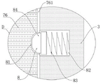
fig. 8 is an enlarged view at D.
In the figure:
1. climbing a ladder I; 2. climbing a ladder II; 3. mounting a box; 4. a socket; 5. inserting plates; 6. a bolt port; 7. a fixing mechanism; 71. a movable block; 72. a bolt; 73. mounting a plate; 74. fixing the spring; 75. a movable plate; 76. a drive member; 761. a chute; 762. a resisting block; 8. a limiting mechanism; 81. a limiting port; 82. an installation port; 83. a limiting spring; 84. a limiting block; 9. a slideway; 10. a push rod; 11. a jack; 12. mounting blocks; 13. and fixing the pin.
Detailed Description
The present invention will be described in further detail with reference to the accompanying drawings.
With reference to figures 1-8 of the drawings,
example 1: a retractable ladder stand comprises a first ladder stand 1 fixedly installed on a wall body and is characterized by further comprising a second ladder stand 2 arranged on the first ladder stand 1 in a sliding mode; the bottom of the back of the first ladder stand 1 is fixedly provided with a mounting box 3, the bottom side wall of the mounting box 3 is provided with two sockets 4, the two sockets 4 are arranged in axial symmetry by taking a median line of the bottom side wall of the mounting box 3 as an axis, the bottom of the back of the second ladder stand 2 is fixedly provided with two plugboards 5, and the plugboards 5 and the sockets 4 are in one-to-one correspondence and are matched for use; and a fixing mechanism 7 for fixing the inserting plate 5 and the ladder stand I1 is arranged in the mounting box 3.
When an operator needs to slide the second crawling ladder 2 into the first crawling ladder 1 for fixing after using the second crawling ladder 2, the operator stands on the back of the second crawling ladder 2 and then directly pushes the second crawling ladder 2 upwards to enable the second crawling ladder 2 to slide upwards on the first crawling ladder 1, the inserting plate 5 at the bottom of the second crawling ladder 2 is inserted into the inserting hole 4 in the mounting box 3, and the inserting plate 5 and the first crawling ladder 1 are fixed through the fixing mechanism 7 in the mounting box 3. When cat ladder two 2 used, operating personnel carried out the unblock to picture peg 5 through fixed establishment 7, alright make cat ladder two 2 in cat ladder 1 up-and-down slip, extended the cat ladder, this retractable cat ladder has increased the tool to lock between two parts cat ladder, guarantees that the idle miscellaneous people can not use the cat ladder at will, and the practicality is strong.
Fixed establishment 7 sets up two movable blocks 71 and two in mounting box 3 including sliding the movable block 71 uses the mounting box 3 end lateral wall median line to set up as the axial symmetry, fixed mounting is close to the bolt 72 of socket 4 one side at movable block 71, two mounting panels 73 and two mounting panels 73 of fixed mounting in mounting box 3 use the mounting box 3 end lateral wall median line to set up as the axial symmetry, fixed mounting is close to the fly leaf 75 of socket 4 one side at every movable block 71, fixed mounting is at the mounting panel 73 and fly leaf 75 between fixed spring 74, the setting is used for driving bolt 72 horizontal migration's driving piece 76 and setting the bolt mouth 6 on two picture peg 5 opposite flank on mounting box 3, bolt mouth 6 and bolt 72 one-to-one and cooperation are used.
The driving part 76 is started, the driving part 76 drives the movable block 71 to pull the fixed spring 74 and the movable plate 75 away from each other on the mounting plate 73 in the mounting box 3, the movable block 71 is away from each other to enable the bolt 72 fixedly mounted with the movable block 71 to be inserted into the bolt opening 6 in the inserting plate 5, the inserting plate 5 and the ladder stand two 2 are fixed, when the ladder stand two 2 is used, the driving part 76 is started, the restoring force of the fixed spring 74 and the movable plate 75 drives the movable block 71 to be close to each other, the bolt 72 on the movable block 71 is enabled to be separated from the bolt opening 6 in the inserting plate 5, the ladder stand two 2 can slide downwards on the ladder stand one 1, the ladder stand two 2 can be movably extended, the structure is simple, and the operation is convenient.
The driving member 76 includes a sliding groove 761 formed in a top side wall of the mounting box 3 and a supporting block 762 slidably disposed in the sliding groove 761, a side surface of the supporting block 762 is attached to a side surface of the movable block 71, and both of the attaching surfaces of the supporting block 762 and the movable block 71 are provided as inclined surfaces.
An operator presses the abutting block 762 downwards, because the side surface of the abutting block 762 is attached to the side surface of the movable block 71 and the attaching surface of the abutting block 762 and the movable block 71 is set to be an inclined surface, the abutting block 762 pushes the movable block 71 to pull the fixed spring 74 and the movable plate 75 on the mounting plate 73 away from each other in the mounting box 3, otherwise, the operator moves the abutting block 762 upwards, and the movable block 71 is driven to approach each other through the restoring force of the fixed spring 74 and the movable plate 75, which is beneficial to driving the bolt 72.
Be provided with on the mounting box 3 and be used for carrying out spacing stop gear 8 to supporting the piece 762, stop gear 8 is including offering on supporting piece 762 leading flank and trailing flank and coaxial spacing mouthful 81, offer on spout 761 lateral wall with spacing mouthful 81 one-to-one and with spacing mouthful 81 coaxial line installing port 82, fixed mounting in installing port 82 spacing spring 83 and the setting of sliding in installing port 82 and with spacing spring 83 end fixed mounting's stopper 84, the stopper 84 sets up to the cambered surface with spacing mouthful 81 binding face the two.
After fixing cat ladder two 2, need fix to supporting piece 762, support piece 762 and contradict the stopper 84 on the spout 761 when the lapse in the spout 761, make stopper 84 receive extrusion force compression limiting spring 83 and contract in installing port 82, when bolt 72 inserts in bolt mouth 6 completely, support spacing mouthful 81 on the piece 762 just to installing port 82 on the spout 761, make stopper 84 card go into limiting mouthful 81 through limiting spring 83's restoring force, fix supporting piece 762, the improvement is to the stability after cat ladder two 2 is fixed.
The bottom side wall of the mounting box 3 is provided with a slide 9, the bottom of the abutting block 762 is fixedly provided with a push rod 10, and the push rod 10 is in sliding fit with the slide 9.
When needs carry out unblock downwardly movable extension to cat ladder two 2, operating personnel only need promote push rod 10 in the slide 9 of mounting box 3 bottom, push rod 10 upwards moves in mounting box 3 and drives rather than fixed mounting's support piece 762 upward movement on spout 761, stopper 84 receives the extrusion force and breaks away from spacing mouth 81 in getting into installing port 82, is favorable to realizing the drive to supporting piece 762, and the setting of push rod 10 can not be operated in the idle miscellaneous people of mounting box 3, just can not use the cat ladder.
The size of the plug board 5 is matched with that of the socket 4, and the size of the plug 72 is matched with that of the plug opening 6; the stability of the first crawling ladder 1 and the second crawling ladder 2 in the fixing process is improved.
A plurality of jacks 11 evenly distributed along the length direction of the second crawling ladder 2 are formed in one vertical side face of the second crawling ladder 2, an installation block 12 is rotatably installed at the bottom of the side edge of the first crawling ladder 1 close to the jacks 11, a fixing pin 13 is arranged on one side, close to the jacks 11, of the installation block 12, and the fixing pin 13 is matched with the jacks 11 for use.
When the second crawling ladder 2 moves to a specified position on the first crawling ladder 1, the fixing pins 13 on the slidable mounting blocks 12 are inserted into the insertion holes 11 in the side edge of the second crawling ladder 2, and the second crawling ladder 2 can be locked after the second crawling ladder 2 is pulled out.
The working principle of the telescopic ladder stand is as follows: when an operator needs to slide the second crawling ladder 2 into the first crawling ladder 1 for fixing after using the second crawling ladder 2, the operator stands on the back surface of the second crawling ladder 2, then directly pushes the second crawling ladder 2 upwards, so that the second crawling ladder 2 slides upwards on the first crawling ladder 1 to insert the inserting plate 5 at the bottom of the second crawling ladder 2 into the inserting hole 4 on the mounting box 3, then presses the abutting block 762 on the mounting box 3 downwards, so that the abutting block 762 slides downwards on the sliding groove 761, because the side surface of the abutting block 762 is attached to the side surface of the movable block 71 and the attaching surface of the abutting block 762 and the movable block 71 is arranged to be an inclined surface, the abutting block 762 pushes the movable block 71 to pull the fixed spring 74 and the movable plate 75 on the mounting plate 73 in the mounting box 3 to be away from each other, and the movable block 71 is away from each other so that the inserting pin 72 fixedly mounted with the movable block 71 is inserted into the inserting hole 6 on the inserting plate 5 to fix the inserting plate 5 and the second crawling ladder 2, after the second crawling ladder 2 is fixed, the abutting block 762 needs to be fixed, when the abutting block 762 slides downwards in the sliding groove 761, the abutting block 762 abuts against the limiting block 84 on the sliding groove 761, the limiting block 84 is compressed by an extrusion force, the limiting spring 83 contracts into the mounting opening 82, when the bolt 72 is completely inserted into the bolt opening 6, the limiting opening 81 on the abutting block 762 is over against the mounting opening 82 on the sliding groove 761, the limiting block 84 is clamped into the limiting opening 81 through the restoring force of the limiting spring 83, the abutting block 762 is fixed, the stability after the second crawling ladder 2 is fixed is improved, when the second crawling ladder 2 needs to be unlocked and movably extended downwards, an operator only needs to push the push rod 10 in the slideway 9 at the bottom of the mounting box 3, the push rod 10 moves upwards in the mounting box 3 to drive the abutting block 762 fixedly mounted with the push rod to move upwards on the sliding groove 761, the limiting block 84 enters the mounting opening 82 under the extrusion force to be separated from the limiting opening 81, the restoring force of the fixed spring 74 and the movable plate 75 drives the movable block 71 to approach each other, so that the pin 72 on the movable block 71 is separated from the pin opening 6 on the plug board 5, the second crawling ladder 2 can slide downwards on the first crawling ladder 1, the second crawling ladder 2 can be movably extended, when the second crawling ladder 2 moves to a specified position on the first crawling ladder 1, the fixed pin 13 on the slidable mounting block 12 is inserted into the jack 11 on the side edge of the second crawling ladder 2, and the second crawling ladder 2 can be locked after being pulled out.
Finally, although the present invention has been described in detail with reference to the preferred embodiments, it should be understood by those skilled in the art that the present invention can be modified or replaced by other means without departing from the spirit and scope of the present invention, which should be construed as limited only by the appended claims.
Claims (6)
1. A retractable ladder stand comprises a first ladder stand (1) fixedly installed on a wall body and is characterized by further comprising a second ladder stand (2) arranged on the first ladder stand (1) in a sliding mode; the mounting box (3) is fixedly mounted at the bottom of the back face of the first ladder stand (1), two sockets (4) are arranged on the bottom side wall of the mounting box (3), the two sockets (4) are arranged in an axisymmetric manner by taking a median line of the bottom side wall of the mounting box (3), two plugboards (5) are fixedly mounted at the bottom of the back face of the second ladder stand (2), and the plugboards (5) and the sockets (4) are in one-to-one correspondence and are matched for use; and a fixing mechanism (7) for fixing the inserting plate (5) and the crawling ladder I (1) is arranged in the mounting box (3).
2. The retractable ladder stand as claimed in claim 1, wherein the fixing mechanism (7) comprises two movable blocks (71) slidably disposed in the mounting box (3) and two movable blocks (71) are disposed in axial symmetry with respect to the centerline of the bottom side wall of the mounting box (3), a pin (72) fixedly mounted on one side of the movable block (71) close to the socket (4), two mounting plates (73) fixedly mounted in the mounting box (3) and two mounting plates (73) are disposed in axial symmetry with respect to the centerline of the bottom side wall of the mounting box (3), a movable plate (75) fixedly mounted on one side of each movable block (71) close to the socket (4), a fixed spring (74) fixedly mounted between the mounting plates (73) and the movable plates (75), a driving member (76) disposed on the mounting box (3) for driving the pin (72) to move horizontally, and pin openings (6) disposed on opposite sides of the two insert plates (5), the bolt openings (6) correspond to the bolts (72) one by one and are matched for use.
3. The retractable ladder stand as claimed in claim 2, wherein the driving member (76) comprises a sliding groove (761) formed in a top side wall of the mounting box (3) and a resisting block (762) slidably disposed in the sliding groove (761), a side surface of the resisting block (762) is abutted against a side surface of the movable block (71), and abutting surfaces of the resisting block (762) and the movable block (71) are both provided as inclined surfaces.
4. The retractable ladder stand as claimed in claim 3, wherein the mounting box (3) is provided with a limiting mechanism (8) for limiting the abutting block (762), the limiting mechanism (8) comprises a limiting opening (81) which is coaxially formed on the front side surface and the rear side surface of the abutting block (762), a mounting opening (82) which is coaxially formed on the side wall of the sliding groove (761) and is one-to-one corresponding to the limiting opening (81), a limiting spring (83) which is fixedly mounted in the mounting opening (82), and a limiting block (84) which is slidably arranged in the mounting opening (82) and is fixedly mounted on the end of the limiting spring (83), and the abutting surfaces of the limiting block (84) and the limiting opening (81) are both provided with cambered surfaces.
5. The retractable ladder stand as claimed in claim 3, wherein a slideway (9) is formed in the bottom side wall of the mounting box (3), a push rod (10) is fixedly mounted at the bottom of the abutting block (762), and the push rod (10) is in sliding fit with the slideway (9).
6. A retractable ladder as claimed in claim 2, wherein: set up a plurality of jacks (11) along cat ladder two (2) length direction evenly distributed on the vertical side of cat ladder two (2), cat ladder one (1) is close to jack (11) side bottom and rotates and installs installation piece (12), one side that installation piece (12) are close to jack (11) is provided with fixed pin (13), fixed pin (13) use with jack (11) cooperation.
Priority Applications (1)
| Application Number | Priority Date | Filing Date | Title |
|---|---|---|---|
| CN202222079280.2U CN217354234U (en) | 2022-08-09 | 2022-08-09 | Retractable cat ladder |
Applications Claiming Priority (1)
| Application Number | Priority Date | Filing Date | Title |
|---|---|---|---|
| CN202222079280.2U CN217354234U (en) | 2022-08-09 | 2022-08-09 | Retractable cat ladder |
Publications (1)
| Publication Number | Publication Date |
|---|---|
| CN217354234U true CN217354234U (en) | 2022-09-02 |
Family
ID=83038484
Family Applications (1)
| Application Number | Title | Priority Date | Filing Date |
|---|---|---|---|
| CN202222079280.2U Active CN217354234U (en) | 2022-08-09 | 2022-08-09 | Retractable cat ladder |
Country Status (1)
| Country | Link |
|---|---|
| CN (1) | CN217354234U (en) |
-
2022
- 2022-08-09 CN CN202222079280.2U patent/CN217354234U/en active Active
Similar Documents
| Publication | Publication Date | Title |
|---|---|---|
| CN112054751B (en) | Photovoltaic power generation equipment of easy installation | |
| CN213018494U (en) | Combined monitoring rod with good stability | |
| CN114961284B (en) | Assembling equipment for container house | |
| CN209867868U (en) | Assembling device for assembling elevator accessories | |
| CN217088326U (en) | Industrial data automatic acquisition control equipment | |
| CN217420703U (en) | Sheet metal part for shared storage space of stereo garage | |
| CN118003060A (en) | Coupling disassembly device | |
| CN212513897U (en) | Auto parts production is with hammering formula sampling machine | |
| CN215287629U (en) | Automatic blocking device capable of being reset manually for automobile elevator | |
| CN115506671A (en) | Heavy lifting-assisting structure for lifting sliding door | |
| CN114427319A (en) | Based on municipal construction is with high security rail guard | |
| CN217051204U (en) | Elevator cab roof convenient to installation | |
| CN220373149U (en) | Modular telescoping device box assembly equipment | |
| CN224244325U (en) | Wall decorative board coupling assembling | |
| CN218388307U (en) | Controller convenient to maintain | |
| CN215671669U (en) | Door lock bolt stop gear | |
| CN218668857U (en) | Construction sound insulation noise reduction device | |
| CN210914898U (en) | Fixing mechanism for elevator car roof | |
| CN222526011U (en) | Movable fence | |
| CN223824558U (en) | Adjustable building support | |
| CN214570304U (en) | Concrete block hoist device | |
| CN221372323U (en) | Hydraulic breaking hammer mounting equipment | |
| CN217267718U (en) | Ground leveling device for building construction | |
| CN214302406U (en) | Indoor partition wall board based on Li nationality pattern design | |
| CN211817875U (en) | Scaffold mesh connector arranged on lifting scaffold |
Legal Events
| Date | Code | Title | Description |
|---|---|---|---|
| GR01 | Patent grant | ||
| GR01 | Patent grant |